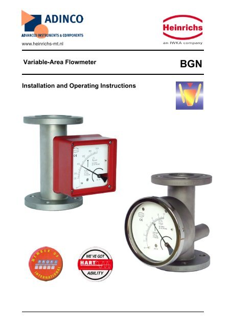
Variable-Area Flowmeter Installation and Operating ... - Adinco bv
Variable-Area Flowmeter Installation and Operating ... - Adinco bv
Variable-Area Flowmeter Installation and Operating ... - Adinco bv

You also want an ePaper? Increase the reach of your titles
YUMPU automatically turns print PDFs into web optimized ePapers that Google loves.
Heinrichs MesstechnikBGN <strong>Installation</strong> <strong>and</strong> <strong>Operating</strong> Instructions5 OutputVarious electrical contact makers or transmitters may beinstalled in the indicator unit.5.1 Binary outputUsing the segments of the slot-type initiators or the eccentricdiscs of the microswitches, any switching point between 10%<strong>and</strong> 90% of the flow rate can be set.5.1.1 KEI 1 or KEI 2 limit transducers1 or 2 limit transducers,type SJ 3,5N, make Pepperl+Fuchs(special switch possible, e.g. SN version)Safety class: PTB Nr. 99 ATEX 2219 XPTB Nr. 00 ATEX 2048 X5.1.2 KEM 1 or KEM 2 limit transducers(special version)Double-throw microswitches whose switching point isactivated by a cam plate.KEM 1 = 1 Double-throw microswitchKEM 2 = 2 Double-throw microswitchesMaximum make-break capacity:230 VAC 50/60Hz 6 A24 VDC 0.5 A110 VDC 0.2 A5.2 Analog output with the ESmagneto-electric transmitterThe magneto-electric transmitter is factory-calibrated to thescale values upon shipment. The signal output is suppliedexclusively in a two-wire connection at 4-20 mA. Normally,the 4-20 mA signal has the HART® protocol; alternatively itcan have PROFIBUS PA.Additional options: 2 limit values, alternatively 1 limit value<strong>and</strong> 1 pulse outputThe signal output <strong>and</strong> the limit values can be configuredusing a HART® modem operating on the followingconfiguration programs: SensorPort from Bopp & Reuther,PDM from Siemens or AMS from Rosemount. Furthermore,a HART® h<strong>and</strong>-held terminal (with DD software) can also beused. For more information about configuration, please referto the separate <strong>Operating</strong> Instructions for the ES.Safety class: DMT 00 ATEX 075 / II2G EEx ia IIC T6When installing electrical equipment in hazardous areas,the conditions <strong>and</strong> provisions specified in the approvaldocmuments must be followed.5.3 Analog output with the KINAX 3W2angle-of-rotation transmitterThe signal output of the angle-of-rotation transmitter isfactory-calibrated to the scale values. The signal output is 4-20 mA in 2-wire connection; or alternatively 0-20 mA in 4- or3-wire connection. The signal output of 4 mA corresponds tothe flow rate scale value of 0 (0 mA for the 0-20 mA version).5.6 mA corresponds to 10% of the flow rate scale value(2 mA). 20 mA corresponds to 100% of the flow rate scalevalue.Use in hazardous areas:The angle-of-rotation transmitter is a component approvedfor hazardous areas. When used in hazardous areas, all thevalues <strong>and</strong> instructions indicated in the certificate of approvalmust be observed. Auxiliary power is fed through anapproved intrinsically safe circuit of 12-30 V. To proveintrinsic safety, only authorized electrical equipment may beinterconnected. Please take note of the maximumpermissible ambient temperature of 60°C/75°C for thetransmitter <strong>and</strong> the process temperature.Safety class:PTB 97 ATEX 2271 / II 2G EEx ia IIC T66 Characteristic values6.1 Measuring accuracy6.1.1 Reference conditionsWater 20°C6.1.2 Measured error(for liquids)BGN-S/H/P +/- 1.6% of URV for local display(URV = upper-range value)(for gases)BGN-S/H/P +/- 2.0% of URV for local displayAdditional inaccuracy for:ES = +/- 0.2%KINAX 3W2 = +/- 0.5%6.1.3 Repeatability+/- 0.5 % of upper-range value6.2 Influence of ambient temperature1. Without electrical equipment <strong>and</strong> with limit transducerwithout influence2. With KINAX transmitter:+/- 0.2 % / 10 K reference temperature 23°C3. With ES transmitter:+/- 0.5 % / 10 K reference temperature 22°C6.3 Influence of fluid temperatureDeviations in fluid temperature from the temperatureobserved during calibration can result in a proportionaldisplay fault because of the corresponding change indensity. Changes in viscosity cause a non-linear displayfault.7 Conditions of useThe VDI/VDE guidelines 3513, Sheet 3, must be observed.The meter is suitable for :1) Liquids with sufficient flowability that are free ofsolids, do not bond <strong>and</strong> do not tend to settle.2) Gases with linear flow behavior <strong>and</strong> an adequateinlet pressure.7.1 Mounting requirementsThe mounting location must be suitable for a verticaldirection of flow from the bottom to the top.Important: If that is impossible, then the device type BGFmay be utilized. This device can be used for both horizontal<strong>and</strong> vertical direction of flow.Page 6 of 30
Heinrichs MesstechnikThe limit values for temperature <strong>and</strong> air humidity at themounting location must be maintained. Avoid corrosiveatmospheres. If this cannot be avoided, ventilation must beinstalled.Please make sure that there is adequate clearance fromparts that might cause magnetic interferences such assolenoid valves <strong>and</strong> ferromagnetic components like steelbrackets/supports. We recommend that the minimum lateraldistance between two adjacently mounted devices be300 mm. The devices can be mounted close together ifvertically offset by one device length. The minimum lateralclearance for interfering steel parts should be 200 mm. Incase of doubt, check the interference by moving the deviceback <strong>and</strong> forth in the selected distance by about 200 mm<strong>and</strong> testing whether the pointer position changes.Select the mounting location so as to enable a reliablereading of the scale values. Please take note as well of thespace requirement for any possible disassembly of thedevice. As a rule, inlet <strong>and</strong> outlet sections in front of <strong>and</strong>behind the device are unnecessary if the medium has alinear flow profile. Avoid mounting accessories convergingon one side in front of the device. However, if this isindispensable maintain a minimum device length of 250 mmas an inlet section.The nominal size of the pipes to be connected mustcorrespond to that of the meter. Avoid fittings converging onone side directly in front of the device. As a rule, installvalves behind the measuring equipment if there are gasesinvolved.7.1.1 Mounting/start-upThe device must be mounted in accordance with thedirection of flow from the bottom to the top (perpendicularly).Please observe the prior reference to the BGF-type device.BGN <strong>Installation</strong> <strong>and</strong> <strong>Operating</strong> InstructionsIf there is risk of dirt or solid matter penetrating the processpipes, flush them beforeh<strong>and</strong> so that these materials do notget caught in the device. Ferromagnetic solid matter suchas spatter can lead to the breakdown of the device. If thesematerials are still present during normal operatingconditions, mount a magnetic filter (accessory) in front of thedevice. When using liquids, flush to avoid a surge of gasbubbles. Slowly increase the supply pressure when usinggases to prevent pressure surges. Basically, avoidactivation using solenoid valves to prevent the float fromshooting upwards.7.1.1.1 Gas measurementWhen using gases, slowly let the operating pressure rise. Atthe same time, vary the operating pressure through a settingvalve so that the float is not knocked around since otherwisethis would damage the measuring element.7.1.2 Device settingsThe measuring equipment is delivered ready for operationaccording to your order specifications. The limittransducers are set to the desired values. If you havesubmitted no requirements, the basic setting for1 contact device: - Minimum contact switching point at 10%of descending flow (damped/closed-circuit principle).2 contact devices: Minimum contact switching point at 10%of descending flow <strong>and</strong> maximum contact switching point at90% of ascending flow.7.1.3 Adjusting the limit transducerThe contacts are adjustable through the contact positionindicators located on the scale. Dismantle the indicatorcover, unfasten the contact position indicators, set to thedesired value <strong>and</strong> reattach them.The nominal size of the device <strong>and</strong> that of the pipes must bethe same. The pressure stages <strong>and</strong>, hence, the dimensionsof the flanges must coincide. The surface roughness of theflange sealing surface must be suitable for the prescribedgaskets.Please check whether possible accessories like springstops, gas/liquid-type dampers are still correctly sitting on theflange. Check whether the mounting clearance between theflanges of the pipes corresponds to the assembly dimensionof the device plus two gaskets. To achieve stress-freemounting, the flanges of the pipes must be aligned parallel toeach other.Use connecting bolts <strong>and</strong> gaskets in the prescribeddimensions. The gaskets must be suitable for the operatingpressure, the temperature <strong>and</strong> the measured medium. WithPTFE-coated devices, use gaskets whose interior <strong>and</strong>exterior diameter correspond to the sealing strip of thedevice.Tighten the screws crosswise so that the processconnections are tight. See to the tightening torques ofscrews especially with PTFE-coated devices.The maximum torques for PTFE-coated devices are:DN15/DN25 = 14 Nm/DN50 = 25 Nm/DN80 = 35 Nm/DN100= 42 Nm (following VDI/VDE Guideline 3513).Please check whether the pipe is adequately stable to ruleout the possibility of vibration or swinging of the device. (Donot use steel mounting parts on the device.)When gas is used as the medium, pay special attention tothe position of the valve. If the device is calibrated to morethan 1.013 bars absolute pressure, the valve is usuallyinstalled behind the flowmeter. At 1.013 bars absolutepressure (free exhaust) install it in front of the device.Page 7 of 30
Heinrichs MesstechnikBGN <strong>Installation</strong> <strong>and</strong> <strong>Operating</strong> Instructions7.1.4 Operation in hazardous areas7.1.4.1 Without electrical equipmentThe basic version of the flowmeter is a non-electrical devicewithout its own ignition sources <strong>and</strong> meets DIN EN 13463-1requirements. It can be used in hazardous areas thatrequire Category 2 equipment.Marking:II 2GD cReg. No.: BVS 03 ATEX H/B 112Tech. File Ref. 03-02 XSince the device does not have its own power sources thatwould result in a temperature increase, the fluid temperatureis decisive for the maximum surface temperature.When used in potentially explosive dust atmospheres, thedevice must be cleaned regularly in order to avoid depositsexceeding 5 mm.7.1.4.2 With built-in electrical limit transducersWhen the limit transducers are installed, the device becomesan electrical assembly <strong>and</strong> receives a marking in accordancewith DIN EN 50014 from the entire device with the built-inelectrical limit transducers.The electrical <strong>and</strong> thermal data <strong>and</strong> the special conditions ofthe EC Type Examination Certificate of the built-in limittransducers must be observed (see also the diagram inSection 7.3.2).The influence of the fluid temperature on the built-in limittransducers must be observed. The overtemperature of themaximum fluid temperature based on the maximum ambienttemperature must be considered with a factor according tothe following table:Nominal sizeFactor forst<strong>and</strong>ardversionDN15 <strong>and</strong> DN25 0.2 0.07DN40 <strong>and</strong> DN50 0.25 0.085DN80 <strong>and</strong> DN100 0.3 0.1Example for built-in limit transducer forDN 15 <strong>and</strong> DN 25:Max. ambient temperature T amb = 40°CMax. fluid temperature T m = 120°CFactor for brought-in heat F = 0.2Temperature classT4T ü =T a =OvertemperatureAmbient temperature oflimit transducerTü = Tm −Tamb= 120 ° C − 40°C = 80°CTa = Tü * F + Tamb = 80°C *0,2 + 40°C = 56°CFactor for thedevice with theindicator pulledforwardIn accordance with the tables in thePTB 99 ATEX 2219 X EC Type Examination Certificate, theSJ 3,5-... N... inductive sensor must be operated in theT5 temperature class with an intrinsically safe circuit thatdoes not exceed the maximum values of the Type 3 circuit.When using the device in hazardous areas, follow theapplicable national installation rules.Example for calculating the max. fluid temperaturebased on the max. ambient temperature for the built-insensor Type ES for DN 15/25.T a = 70°CT amb = 60°CF = 0.2⎛ Ta −Tamb⎞ ⎛ 70 ° C − 60°C ⎞Tm = ⎜ ⎟ + Tamb = ⎜⎟ + 60°C = 110°C⎝ F ⎠ ⎝ 0,2 ⎠7.1.4.2.1 Marking for the device when theSJ 3,5...N... limit transducer is built inPTB 99 ATEX 2219 XII 2G EEx ia IIC T6-T47.1.4.2.2 Marking for the device when the ES magnetoelectrictransmitter is built inDMT 00 ATEX 075II2G EEx ia IIC T67.1.4.2.3 Marking for the device when the KINAX 3W2angle-of-rotation transmitter is built inPTB 97 ATEX 2271II 2G EEx ia IIC T67.2 Ambient conditions7.2.1 Ambient temperature rangesWithout electrical accessories:-40°C to +80°CWith limit transducer:-40 °C to +65°CWith KINAX signal output:-40°C to +60°CWith ES signal output:-40°C to +70°CFor the hazardous area version, take note of the maximumambient temperatures depending on the temperature classas specified in the Type Examination Certificate.7.2.2 Storage temperatureThe storage temperatures are identical to the ambienttemperature ranges.7.2.3 Climatic categoryWeather-protected <strong>and</strong>/or unheated locations, class C7.2.4 Degree of protectionIP 657.2.5 Shock resistance/vibration resistanceThe meter should be protected from extreme shocks <strong>and</strong>vibrations, which could cause damage.7.2.6 Electromagnetic compatibilityEN 61000-6-2:1999 Immunity industrial environmentEN 50081-1 Emitted interference residential environmentEN 55011:1998+A1:1999 Group 1, Class BNAMUR recommendation NE 21Page 8 of 30
Heinrichs MesstechnikBGN <strong>Installation</strong> <strong>and</strong> <strong>Operating</strong> Instructions7.3 Fluid conditions7.3.1 Fluid temperature rangesBGN-S/H : - 40°C to +200°CSpecial design: -80°C to +350°CBGN-P : - 20°C to +125°C7.3.2 Diagrams: Max. ambient temperature based on the fluid temperature for the ESSt<strong>and</strong>ard version70,0Max. ambient temperature [°C]60,050,040,030,020,070 80 90 100 110 120 130 140 150 160 170 180 190 200Fluid temperature [°C]DN15/25 DN40/50 DN80/100Indicator pulled forward70,0Max. ambient temperature [°C]65,060,055,070 80 90 100 110 120 130 140 150 160 170 180 190 200Fluid temperature [°C]DN15/25 DN40/50 DN80/100Page 9 of 30
Heinrichs MesstechnikBGN <strong>Installation</strong> <strong>and</strong> <strong>Operating</strong> Instructions7.3.3 Fluid pressure limitSt<strong>and</strong>ard design BGN-S/H – DN 15/25/40/50/80 PN 40;DN 100 PN 16Special design – up to PN 400BGN-P – DN 15/25/50/80/100 PN 167.3.4 Inlet <strong>and</strong> outlet sectionsInlet <strong>and</strong> outlet sections are not required for a linear flowprofile of the fluid. For an extremely non-linear flow profile(e.g. shut-off/control valves are located in front of the meter),we recommend an inlet section with a mounting length of250 mm (see also guidelines in accordance withVDI/VDE 3513).7.3.5 Physical stateLiquid or gaseous7.3.6 DensityLiquids: up to 2.0 kg/lGases: no restrictions7.3.7 ViscosityThe influence of viscosity depends on various factors.Therefore, it must be calculated for each application.7.3.8 Pressure (for gas measurement)The measured values only apply to the calibrated fluid datastated on the scale. Any change or deviation in pressure willcause a display fault.7.3.9 Pressure lossDepends on the meter size <strong>and</strong> the measuring range (seeMeasuring range table).Page 10 of 30
Heinrichs MesstechnikBGN <strong>Installation</strong> <strong>and</strong> <strong>Operating</strong> Instructions8 Construction details8.1 Type of construction/dimensions8.1.1 Aluminum indicator housing8.1.2 Dimension drawing for heatingconnectionDeviating mounting dimensions:(1) With preceding magnetic filter, 50 mm longerplus 2 gaskets(2) 265 mm with the indicator pulled forward(3) 175 mm with the indicator pulled forward(4) For special design DN 100: 120 mm8.1.2.1 Connections for heating jacketPipe forErmeto 12 mmFlange in acc. with DIN DN 15 or DN 25 PN 40Flange in acc. with ANSI ½“ 150 lbsThe DN 25 flange is a special version.Dimensions:DN PN Inside diameter A15 40 26 7425 40 32 7740 40 46 8850 40 70 9780 16 102 113Page 11 of 30
Heinrichs MesstechnikBGN <strong>Installation</strong> <strong>and</strong> <strong>Operating</strong> Instructions8.1.3 Indicator housing made of stainlesssteel8.2 WeightNominal size Weight [kg]DN 15 3DN 25 4.2DN 40 6DN 50 7.5DN 80 13DN 100 18Nominal size¾“, 150 lbs, ANSIB16.51“, 150 lbs, ANSIB16.51 ½“, 150 lbs, ANSIB16.52“, 150 lbs, ANSIB16.53“, 150 lbs, ANSIB16.54“, 150 lbs, ANSIB16.5Weight [kg]34.267.51318Nominal size¾“, 300 lbs, ANSIB16.51“, 300 lbs, ANSIB16.51 ½“, 300 lbs, ANSIB16.52“, 300 lbs, ANSIB16.53“, 300 lbs, ANSIB16.54“, 300 lbs, ANSIB16.5Weight [kg]3.44.76.88.514.520DN PN Inside diameter A15 40 26 10025 40 32 10340 40 46 11050 40 70 12280 16 102 138Deviating mounting dimensions:(1) 265 mm with the indicator pulled forwardPage 12 of 30
Heinrichs MesstechnikBGN <strong>Installation</strong> <strong>and</strong> <strong>Operating</strong> Instructions8.3 MaterialFittingType Measuring tube Lining of Flanges Flange lining FloatmeasuringtubeBGN – S Stainless steel none Stainless steel none Stainless steelBGN – P Stainless steel PTFE Stainless steel PTFE PTFEBGN – H DN15/25 ¾“/1“ Hastelloy HC4 none Hastelloy HC4 none Hastelloy HC4BGN – H > DN40 / 1½” Hastelloy HC4 none Stainless steel Hastelloy HC4 Hastelloy HC4IndicatorType Base plate HousingBGN – S/P/H Aluminum Aluminum, safety glass windowOptional Stainless steel Stainless steel, safety glass window8.4 Process connectionBGN-S/HBGN-PDN 15 PN 40 PN 16DN 25 PN 40 PN 16DN 40 PN 40 PN 16DN 50 PN 40 PN 16DN 80 PN 40 PN 16DN 100 PN 16 PN 16BGN S/ HBGN PANSI ¾“ B16.5 150 lbs 1) 300 lbs 1) 150 lbs 2) 300 lbs 2)ANSI 1“ B16.5 150 lbs 1) 300 lbs 1) 150 lbs 2) 300 lbs 2)ANSI 1 ½“ B16.5 150 lbs 1) 300 lbs 1) 150 lbs 2) 300 lbs 2)ANSI 2“ B16.5 150 lbs 1) 300 lbs 1) 150 lbs 2) 300 lbs 2)ANSI 3“ B16.5 150 lbs 1) 300 lbs 1) 150 lbs 2) 300 lbs 2)ANSI 4“ B16.5 150 lbs 2) 300 lbs 2) 150 lbs 2) 300 lbs 2)1) Entire device PN 40 2) Entire device PN 16Additional equipment: special flanges, union, food connection, welding connectionThe S/H versions in special design are available up to PN 400.8.5 Magnetic filterThe BGN flowmeter is sensitive to impure media. Beforeinstalling the device, clean the pipes of dirt, spatter <strong>and</strong> otherforeign matter. If the medium comes with solid particles,connect a suitable filter in series. When dealing with flowmedia with ferrous particles, we recommend the connectionof a magnetic filter.To protect both magnetic filter types, MF-S (stainless steel)<strong>and</strong> MF-P/S (PTFE/stainless steel), from corrosion,encapsulated permanent magnets are laid out in spiral form.The spiral mounting produces optimum effect at smallpressure loss. The filter can be supplied with groove ortongue, projection or return, other st<strong>and</strong>ards or specialconnections according to customer wishes.Dimensions:DNg (mm)15 4525 6840 8850 10265 12280 138100 158Page 13 of 30
Heinrichs MesstechnikBGN <strong>Installation</strong> <strong>and</strong> <strong>Operating</strong> Instructions8.6 Electrical connectionWiringTo connect the auxiliary power, remove the indicator cover, insert the connector cable into the cable gl<strong>and</strong> <strong>and</strong> attach it to theterminals according to terminal diagram. Tighten the cable gl<strong>and</strong> securely, remount the indicator cover <strong>and</strong> close it tightly.8.6.1 Wiring diagram for ES transmitter (signal output 4-20 mA with HART®)8.6.2 Wiring diagram for ES transmitter with 4-20 mA output <strong>and</strong> 2 limit transducersPage 14 of 30
Heinrichs MesstechnikBGN <strong>Installation</strong> <strong>and</strong> <strong>Operating</strong> Instructions8.6.3 Wiring diagram for ES transmitter with 4- 20 mA output, pulse output <strong>and</strong> limit transducer8.6.4 Wiring diagram for inductive limit transducersPage 15 of 30
Heinrichs MesstechnikBGN <strong>Installation</strong> <strong>and</strong> <strong>Operating</strong> Instructions8.6.5 Wiring diagram for KINAX 3W2 transmitter with 4-20 mA output, 2 wires8.6.6 Wiring diagram for KINAX 3W2 transmitter with 4-20 mA output, 3 wiresPage 16 of 30
Heinrichs Messtechnik21 Exploded viewsBGN <strong>Installation</strong> <strong>and</strong> <strong>Operating</strong> Instructions21.1.2 BGN-.... with spring stop21.1 Fitting with measuring elementName(Figures 12-16)Part no.Fitting 1Float 2Spring stop for float 3 / 4Cone with float, gasket <strong>and</strong> stop(Fig. 16)2/3/4Complete BGN gas damping setwith float (Fig. 14)2/3/443221.1.1 BGN-.... St<strong>and</strong>ard version12Figure 1321.1.3 BGN-.... with damping piston143Figure 1221Figure 14Page 20 of 30
Heinrichs MesstechnikBGN <strong>Installation</strong> <strong>and</strong> <strong>Operating</strong> Instructions21.1.4 BGN-.... with damping piston <strong>and</strong>spring stop4321Figure 1521.1.5 BGN-.... small measuring ranges1234Figure 16Page 21 of 30
Heinrichs Messtechnik21.2 Indicator unitNamePartno.Mounting plate with 1 thread M 20 x 1.5 10Mounting plate with 2 threads M 20 x 1.5 11Bearing unit 20Fixing screws for bearing unit 30Dummy plug M 20 x 1.5 40Cable gl<strong>and</strong> 41Cable gl<strong>and</strong> 42Scale, blank 50Scale, product scale according to original shipment (order no.necessary)51Screw for fixing the scale 60Zero-point screw with nut 70Indicator cover with glass window, gasket, screws 80Scale pointer with hub 90Scale pointer with hub <strong>and</strong> 2 switching dials 91Scale pointer with hub <strong>and</strong> linearization disc 92Scale pointer with hub <strong>and</strong> linearization disc/switching dial 93Scale pointer with hub <strong>and</strong> 2 switching dials <strong>and</strong> ES positionmagnet941. SJ 3,5 N limit transducer with limit value indicator 1101. SJ 3,5 SN limit transducer with limit value indicator 1112. SJ 3,5 N limit transducer with limit value indicator 1202. SJ 3,5 SN limit transducer with limit value indicator 121Connection plate for 1 limit transducer with mounting parts 130Connection plate for 2 limit transducers with mounting parts 131<strong>Installation</strong> set for transmitter type KINAX 3W2 Ex withlever arm <strong>and</strong> mounting parts132<strong>Installation</strong> set transmitter type KINAX 3W2 Ex withlever arm <strong>and</strong> mounting parts <strong>and</strong> connection for a limit 133transducer<strong>Installation</strong> set transmitter ES Ex Hart 140<strong>Installation</strong> set transmitter ES Ex with switch (min-max) 141<strong>Installation</strong> set transmitter ES Ex with Profibus 14221.2.1 Complete indicator unit, local withscaleBGN <strong>Installation</strong> <strong>and</strong> <strong>Operating</strong> Instructions21.2.2 Complete indicator unit with 1 SJ 3,5N limit transducer706030Figure 221.2.3 Complete indicator unit with 2 SJ 3,5N limit transducers805070110111911302030411080805070707060507060120121110111909120131303020303040Figure 1Figure 3411010Page 22 of 30
Heinrichs MesstechnikBGN <strong>Installation</strong> <strong>and</strong> <strong>Operating</strong> Instructions21.2.4 Complete indicator unit with E2KINAX Ex transmitter21.2.6 Indicator unit with transmitter typeES Ex HART®80805050707070706060(141)(142)140949220132303030203042Figure 441Figure 6101021.2.5 Complete indicator unit with E2KINAX Ex transmitter <strong>and</strong> 1 SJ 3,5 N limittransducer706011011130Figure 58050709313320304111NamePartno.Mounting plate with 1 thread M 20 x 1.5 10Mounting plate with 2 threads M 20 x 1.5 11Bearing unit 20Fixing screws for bearing unit 30Dummy plug M 20 x 1.5 40Cable gl<strong>and</strong> 41Cable gl<strong>and</strong> 42Scale, blank 50Scale, product scale according to original shipment (orderno. necessary)51Screw for fixing the scale 60Zero-point screw with nut 70Indicator cover with glass window, gasket, screws 80Scale pointer with hub 90Scale pointer with hub <strong>and</strong> 2 switching dials 91Scale pointer with hub <strong>and</strong> linearization disc 92Scale pointer with hub <strong>and</strong> linearization disc/switchingdial93Scale pointer with hub <strong>and</strong> 2 switching dials <strong>and</strong> ESposition magnet941. SJ 3,5 N limit transducer with limit value indicator 1101. SJ 3,5 SN limit transducer with limit value indicator 1112. SJ 3,5 N limit transducer with limit value indicator 1202. SJ 3,5 SN limit transducer with limit value indicator 121Connection plate for 1 limit transducer with mountingparts130Connection plate for 2 limit transducers with mountingparts131<strong>Installation</strong> set for transmitter type KINAX 3W2 Ex withlever arm <strong>and</strong> mounting parts132<strong>Installation</strong> set transmitter type KINAX 3W2 Ex with leverarm <strong>and</strong> mounting parts <strong>and</strong> connection for a limit 133transducer<strong>Installation</strong> set transmitter ES Ex Hart 140<strong>Installation</strong> set transmitter ES Ex with switch (min-max) 141<strong>Installation</strong> set transmitter ES Ex with Profibus 142Page 23 of 30
Heinrichs MesstechnikBGN <strong>Installation</strong> <strong>and</strong> <strong>Operating</strong> Instructions22 Decontamination certificate for device cleaningCompany: ............................... City: ...................................Department: ......................... Name: ..............................Tel: .............................This variable-area flowmetertype BGN-.........was operated using the measured medium..................................................................Since this measured medium is dangerous in water/poisonous/corrosive/flammable,we have- checked that all hollow spaces of the device are free of these materials*- neutralized <strong>and</strong> flushed all hollow spaces of the device**cross out what is not applicable.We hereby confirm that in resending the device no danger to persons or theenvironment is posed by the residual measured substance.Date: ............................. Signature: ...........................StampPage 24 of 30
Heinrichs MesstechnikBGN <strong>Installation</strong> <strong>and</strong> <strong>Operating</strong> Instructions23 EC Type Examination CertificatePage 25 of 30
Heinrichs MesstechnikBGN <strong>Installation</strong> <strong>and</strong> <strong>Operating</strong> InstructionsPage 26 of 30
Heinrichs MesstechnikBGN <strong>Installation</strong> <strong>and</strong> <strong>Operating</strong> InstructionsPage 27 of 30
Heinrichs MesstechnikBGN <strong>Installation</strong> <strong>and</strong> <strong>Operating</strong> InstructionsPage 28 of 30
Heinrichs MesstechnikBGN <strong>Installation</strong> <strong>and</strong> <strong>Operating</strong> InstructionsPage 29 of 30
Heinrichs MesstechnikBGN <strong>Installation</strong> <strong>and</strong> <strong>Operating</strong> Instructions24 Sales representatives25 Noteswww.heinrichs-mt.nlTel. +31 (0) 345 59 60 00Fax +31 (0) 345 59 60 01Page 30 of 30
Since 1970Representative forHeinrichsEin Unternehmen der IWKA Gruppewww.heinrichs-mt.nl<strong>Adinco</strong> <strong>bv</strong>P.O.Box 904190 CB GeldermalsenNetherl<strong>and</strong>sTel. +31 (0) 345 59 60 00Fax +31 (0) 345 59 60 01E-mail: info@adinco.nlInternet: www.adinco.nl