
You also want an ePaper? Increase the reach of your titles
YUMPU automatically turns print PDFs into web optimized ePapers that Google loves.
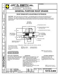
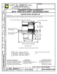
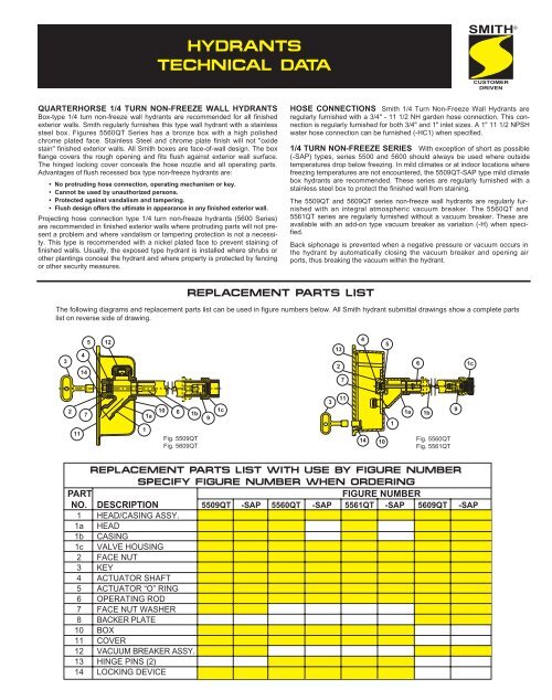
HYDRANTSTECHNICAL DATASMITH ®CUSTOMERDRIVENQUARTERHORSE 1/4 TURN NON-FREEZE WALL HYDRANTSBox-type 1/4 turn non-freeze wall hydrants are recommended for all finishedexterior walls. Smith regularly furnishes this type wall hydrant with a stainlesssteel box. Figures 5560QT Series has a bronze box with a high polishedchrome plated face. Stainless Steel and chrome plate finish will not "oxidestain" finished exterior walls. All Smith boxes are face-of-wall design. The boxflange covers the rough opening and fits flush against exterior wall surface.The hinged locking cover conceals the hose nozzle and all operating parts.Advantages of flush recessed box type non-freeze hydrants are:• No protruding hose connection, operating mechanism or key.• Cannot be used by unauthorized persons.• Protected against vandalism and tampering.• Flush design offers the ultimate in appearance in any finished exterior wall.Projecting hose connection type 1/4 turn non-freeze hydrants (5600 Series)are recommended in finished exterior walls where protruding parts will not presenta problem and where vandalism or tampering protection is not a necessity.This type is recommended with a nickel plated face to prevent staining offinished walls. Usually, the exposed type hydrant is installed where shrubs orother plantings conceal the hydrant and where property is protected by fencingor other security measures.HOSE CONNECTIONS Smith 1/4 Turn Non-Freeze Wall <strong>Hydrants</strong> areregularly furnished with a 3/4" - 11 1/2 NH garden hose connection. This connectionis regularly furnished for both 3/4" and 1" inlet sizes. A 1" 11 1/2 NPSHwater hose connection can be furnished (-HC1) when specified.1/4 TURN NON-FREEZE SERIES With exception of short as possible(-SAP) types, series 5500 and 5600 should always be used where outsidetemperatures drop below freezing. In mild climates or at indoor locations wherefreezing temperatures are not encountered, the 5509QT-SAP type mild climatebox hydrants are recommended. These series are regularly furnished with astainless steel box to protect the finished wall from staining.The 5509QT and 5609QT series non-freeze wall hydrants are regularly furnishedwith an integral atmospheric vacuum breaker. The 5560QT and5561QT series are regularly furnished without a vacuum breaker. These areavailable with an add-on type vacuum breaker as variation (-H) when specified.Back siphonage is prevented when a negative pressure or vacuum occurs inthe hydrant by automatically closing the vacuum breaker and opening airports, thus breaking the vacuum within the hydrant.REPLACEMENT PARTS LISTThe following diagrams and replacement parts list can be used in figure numbers below. All Smith hydrant submittal drawings show a complete partslist on reverse side of drawing.34145 1213274561c211711a 10 6 1bFig. 5509QTFig. 5609QT91c311141011a1bFig. 5560QTFig. 5561QT9REPLACEMENT PARTS LIST WITH USE BY FIGURE NUMBERSPECIFY FIGURE NUMBER WHEN ORDERINGPARTFIGURE NUMBERNO. DESCRIPTION 5509QT -SAP 5560QT -SAP 5561QT -SAP 5609QT -SAP1 HEAD/CASING ASSY.1a HEAD1b CASING1c VALVE HOUSING2 FACE NUT3 KEY4 ACTUATOR SHAFT5 ACTUATOR “O” RING6 OPERATING ROD7 FACE NUT WASHER8 BACKER PLATE10 BOX11 COVER12 VACUUM BREAKER ASSY.13 HINGE PINS (2)14 LOCKING DEVICE
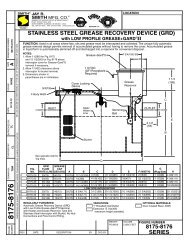
SMITH ®HYDRANTS TECHNICAL DATA ANDOPTIONAL INLET CONNECTIONSCUSTOMERDRIVENNON-FREEZE GROUND AND POST HYDRANTS are supplied with a specialvalve housing which prevents freezing of hydrant during non-use periods.The valve housing must be installed below the frost line (minimum depth ofbury) which prevails for the area of installation. The valve housing has adrain hole which drains the casing of hydrant when hydrant is shut off. Ineffect, there is no water in the casing during non-use periods. Normally,water from the drain hole is allowed to drain into the ground. The valve housingshould be set in a bed of gravel so that water drained from casing canleach into ground.FinishedExteriorWallAWallThicknessThis is the dimensionto the valve housing.FinishedExteriorWallAWallThicknessThis is the dimension to the valve housing.Some locations which require Non-Freeze Ground <strong>Hydrants</strong> cannot toleratewater draining from the drain hole. Examples are parking garages, plazas,and roof decks used for recreational purposes. Often in this type of applicationthe valve housing will protrude into a finished area which is not subject tofreezing temperatures. To eliminate the problem of water drainage in thistype of installation, Smith can supply a tapped drain hole in the hydrant boxand a tapped drain hole in the valve housing. By using the tapped drain hole,water accumulation in the box, and the normal drain down water from thevalve housing drain hole can be piped to a suitable drain.SPECIFYING WALL SIZE Primary function of both 5500 and 5600 Series1/4 Turn Non-Freeze Wall <strong>Hydrants</strong> is to supply water to the building exteriorwithout danger of freezing, regardless of how low the outside temperaturefalls. For this reason, the hydrant must be specified with a casing longenough to locate the valve seat inside the heated building. (Fig. 1) showshow to determine proper size required.NOTE: All wall hydrant series are available in short as possible types for mild climateinstallation. Specify series number -SAP.OPTIONAL INLET CONNECTIONSAdjustable Wall Clamp(When Specified)Fig. 1Adjustable Wall Clamp(When Specified)NOTE: When ordering, specify Figure Number and "A" dimension. "A" should always begreater than wall thickness for non-freeze installations. When a wall clamp is specified, add 11/4" to the wall thickness to arrive at a minimum required "A." The "A" specified should be thenext larger, even number; such as 6", 8", 10", etc. Wall hydrants are furnished in lengths of 2"increments.Often, non-freeze wall hydrants must be concealed entirely within the wall.When so required, an overall dimension can be specified. This dimension ismeasured from face of hydrant box to extreme end of inlet connection. Whenthe valve seat must be concealed within the wall, extra precautions must be takento properly insulate the valve seat housing to protect against freezing.3/4" NPT2 3/83/4" NPT2 3/83/4" NPT2 3/83/4" NPT Male1" NPT MaleFor 3/4" Copper Tubing Female Sweat ConnectionSUFFIX -EUNION ELBOW - 3/4" NPTSUFFIX -E1UNION ELBOW - 1" NPTSUFFIX -SEUNION ELBOW -SWEAT -3/4”3/4" NPT23/4" NPT23/4" NPT2For 3/4" Copper TubingFemale Sweat ConnectionFor 1" Copper TubingFemale Sweat Connection1" NPT FemaleSUFFIX -SSSTRAIGHT SWEAT - 3/4"SUFFIX -SS-1STRAIGHT SWEAT - 1"SUFFIX -MF1STRAIGHT FEMALE - 1"HydrantCasing3/4" Male NPTUNIVERSAL INLET CONNECTION1/2" Female NPTUnion GroundJoint<strong>Hydrants</strong> are regularly furnished with a unique inlet connection, 3/4"NPT Male thread, 1/2" NPT Female thread, and union ground joint carefullyengineered to accommodate inlet connections shown above.
SMITH23SMITH472437SMITH8537 8 9SMITH ®611a1b10b10c1c8910a10141513Fig. 5810181610171a10a1910a10b1a101b10b1b19Fig. 5812 10c1cFig. 59101514111210c1413151c 13CUSTOMERDRIVENREPLACEMENT PARTS LIST WITH USE BY FIGURE NUMBERSPECIFY FIGURE NUMBER WHEN ORDERINGPARTFIGURE NUMBERNO. DESCRIPTION 5810 -F 5811 -F 5812 5813 5814 5910 5911 5912 5913 5914 5950 59511 HEAD/CASING ASSY.1a HEAD1b CASING1c VALVE HOUSING2 LOCKING DEVICE3 KEY4 COVER5 HINGE PINS (2)6 BOX7 FACE NUT8 OPERATING SCREW9 OPERA. SCR. "O" RING10 OPERA. ROD ASSY.10a COUPLING10b ROD10c PLUNGER11 WASHER SCREW12 WASHER NEOPRENE13 REMOVABLE SEAT14 PLUNGER "O" RING15 PLUNGER "O" RING16 LIFTING DEVICE17 FACE NUT SEAT18 FACE NUT SEAT GASKET19 CASING GUARD11a17183SMITH78910a10b65341671018SMITH191b1a91b10aFig. 59121c10c141112 13Fig. 595010b1c15 131010c14