passerotti-wibroizolatory SAW
passerotti-wibroizolatory SAW
passerotti-wibroizolatory SAW
- No tags were found...

You also want an ePaper? Increase the reach of your titles
YUMPU automatically turns print PDFs into web optimized ePapers that Google loves.
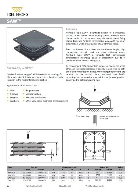
<strong>SAW</strong>Note: The natural frequencies and degrees of isolation are based on dynamic characteristics of the mountings.Loadper mounting (kg)To select correct mounting, following dataare needed:1) Load per mounting (kg)2) Interfering frequency (Hz)(Hz = rpm / 60 )Select correct load line in diagram 1 andcorrect interference line in diagram 3.The load line intersects with required typeof mounting.Connect this intersection point verticallydown to the interference line in diagram 3.Here, on the sloping curve, the isolationdegree is indicated.For static deflection, see diagram 2.75
<strong>SAW</strong>Note: The natural frequencies and degrees of isolation arebased on dynamic characteristics of the mountings.This page refers to shear load characteristics only!Loadper mounting (kg)Fmax (Kg)<strong>SAW</strong> 125<strong>SAW</strong> 150<strong>SAW</strong> 200<strong>SAW</strong> 30040º IRH240330600157560º IRH5708501200315040003000Diagram 1Diagram 225002000<strong>SAW</strong> 300-6015001200100090080070060050040030025020015012010090807060<strong>SAW</strong> 300-40<strong>SAW</strong> 200-40<strong>SAW</strong> 150-40<strong>SAW</strong> 125-40<strong>SAW</strong> 150-60<strong>SAW</strong> 125-60<strong>SAW</strong> 200-60<strong>SAW</strong> 300-60<strong>SAW</strong> 125-60<strong>SAW</strong> 200-40<strong>SAW</strong> 150-40<strong>SAW</strong> 125-40<strong>SAW</strong> 200-60<strong>SAW</strong> 300-40<strong>SAW</strong> 150-60502 2.5 3 3.5 45 6 7 8 9 10 5 6 8 10 12 15 20 25 30 40 50Interfering frequency (Hz)Natural frequency (Hz)Static deflection (mm)2Diagram 3To select correct mounting, following dataare needed:31) Load per mounting (kg)2) Interfering frequency (Hz)4(Hz = rpm / 60 )Select correct load line in diagram 1 andcorrect interference line in diagram 3.6The load line intersects with required typeof mounting.Connect this intersection point vertically8down to the interference line in diagram 3.10Here, on the sloping curve, the isolationdegree is indicated.12For static deflection, see diagram 2.1505020702580308590405060ResonanceAvoid this region80100Degree of isolation (%)76