E89_prospect.pdf (ENG) - Iskraemeco
E89_prospect.pdf (ENG) - Iskraemeco
E89_prospect.pdf (ENG) - Iskraemeco

You also want an ePaper? Increase the reach of your titles
YUMPU automatically turns print PDFs into web optimized ePapers that Google loves.
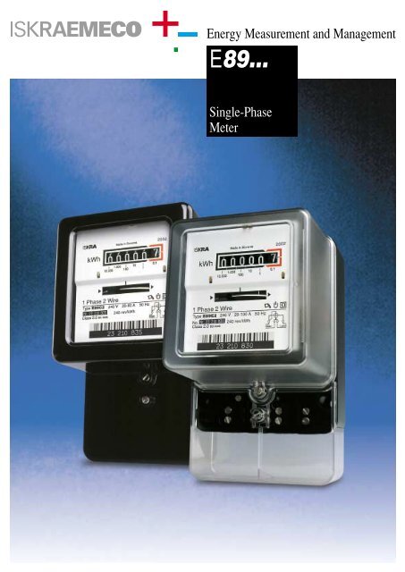
Energy Measurement and Management<strong>E89</strong>...Single-PhaseMeter
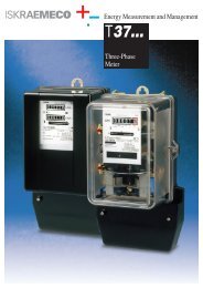
<strong>E89</strong>...SINGLE-PHASE METERS TYPE <strong>E89</strong>APPLICATIONThe standard single-phase meter is intended for measuring active electricalenergy in two-wire, single-phase networks, where relatively high changesoccur in measuring power, and deviations from referential condition are present.Connection is direct or over instrument transformers. Meters are surfacemounting types.RATINGSThe measuring-technical characteristics comply to EN publ. 60521, BS 5685,BS EN 60521 and AS 1284 Part 1. The accuracy class is 2.DESIGNThe following versions of meters are manufactured:Type <strong>E89</strong>B for 300 % current loadingType <strong>E89</strong>C for 400 % current loadingType <strong>E89</strong>E for 500 % current loadingType <strong>E89</strong>F for 600 % current loadingType <strong>E89</strong>G for 666 % current loadingThe symbols added to the type designation indicate the following:D: double tariff type meter (<strong>E89</strong>CD)T: meter for connection via measuring transformers (<strong>E89</strong>CT)2: meter with magnetic bearing (<strong>E89</strong>F2)-5: meter with inductive pulse transmiter (<strong>E89</strong>C2-5)– Semiconductor output (S0 – DIN 43864/86)-9: meter with optoelectronic pulse transmiter (<strong>E89</strong>C-9)– OPTO-MOS relay output (voltage free) or– semiconductor output (S0 – DIN 43864/86)VOLTAGE RANGEDirect operating meters: 120 V, 240 V (50 or 60 Hz)Transformer operated meters: 100 V, 240 V(other voltages between 100 and 500 V are also possible)CURRENT RANGEDirect operating meters: 5–20, 10–40, 20–80, 20–100, 10–60, 15–100 A(other current ranges to maximum 100 A are also possible)Transformer operated meters: 2.5–10, 3–6 ACONSTRUCTIONMETER CASEThe meter case is adapted for tropicalconditions as non-hygroscopicand complies with the flame testgiven in BS5685, Appendix B(clause 5.6)Meter baseis made of moulded insulating blackmaterial (bakelite), highly resistant tocreep currents. It makes an integralpart with the meter terminal block.Connection terminals are insertedinto the terminal aperture from theinside of meter base, and are madeof nickel plated brass. The diameterof a terminal hole is up to 9.5 mm,suitable for connection of externalconductors. Each terminal isprovided with two M6 clampingscrews. The hook is fixed to the baserear side. A carrying handle can beprovided on special request.Terminal coveris insulation-type made of bakelite asthe meter base, or it can be transparentmade of modified polymethylmethacrylateas a standard version,or polycarbonate on request.It protects the terminal block againstunauthorised access. The terminalblock is sealed with one sealingscrew independently of the metercover and can be short or extended.Extended cover type meters are normallysupplied unless short terminalcover is requested. A connectiondiagram is impressed into theterminal cover from the inside.213564SETTING ELEMENTSare easily accessible and are manually adjusted without special tools.Interactive setting influences are at a minimum.1 – starting adjustment2 – coarse braking element adjustment3 – fine braking element adjustment4 – low load adjustment5 – coarse adjustment of inductive load6 – fine adjustment of inductive load
<strong>E89</strong>...Meter coveris insulation-type made of bakelite asthe meter base, or it can be transparentmade of modified polymethylmethacrylateas a standard version,or of polycarbonate on request.The bakelite cover is provided with aglass window through which themeter register can be read and therotor observed. The window is fixedinto the cover by means of four fixingwashers and sealed with siliconcompound. A sealing gasket in thecover prevents the penetration ofdust, humidity or other particles intothe meter. Both covers are providedwith two sealing screws.DRIVING SYSTEMA tangential driving system isattached to a supporting frame. Thevoltage electro-magnet is woundonto a coil of thermoplastic material,sealed with duropol and covered witha shrinkable plastic tube allowing fora high break-down strength. Thewinding of the current electro-magnetis located on the divided coil ofplastic material and is thereby insulatedagainst the core. The beginningand the end of the winding can beattached to the terminal directly orover a filament wire soldered to theterminal. Both the current and voltageelectro-magnets are positionedon the frame with a plug.METER ROTORThe rotor is a light, circular, rigidstamping of electrolytic aluminium,90 mm in diameter and 1 mm thick,die-cast with aluminium alloy to astainless steel spindle.On request 100 radial, equal blackdivisions can be printed around thecircumference to allow stroboscopiccalibration and testing. The blackmark for observation of meter rotationis printed out on the top surfaceof the disc. The register is driven by amoulded worm, made of polyamide,which is fitted to the spindle. Agraphite sleeve is impressed into theworm on the upper part of the shaft.An optional extra reverse runningstop can be fitted to the meter to preventregistration under conditions ofreverse power flow.BRAKING MAGNETThe braking magnet is a two-directionalversion. The U-shaped magneticcubes are of AlNiCo alloy with highcoercivity which reduces the influenceof short-circuit thrusts on themeasuring accuracy of the meter. Awide range of rotor speed settings ispossible by moving the whole magnet,and fine speed setting is guaranteedwith a micro-meter control.Large temperature compensation isprovided with the compensationplates made of a special alloy.TECHNICAL DATADIRECT OPERATING METERSType <strong>E89</strong>C <strong>E89</strong>E <strong>E89</strong>F <strong>E89</strong>GReference voltage U r 240 VReference frequency f r 50 HzBasic – Maximum current I b –I m 5–20 A 10–40 A 20–80 A 20–100 A 10–60 A 15–100 AThermal current 24 A 48 A 120 A 72 A 120 ASelf-consumption: 0.9 W 0.9 W 1 W 0.9 W– voltage electro-magnet3.7 VA 4.25 VA 3.9 VA 4.25 VA– current electro-magnet at I b 0.26 W 0.18 W 0.26 W 0.12 W 0.14 W0.40 VA 0.35 VA 0.38 VA 0.23 VA 0.21 VATorque at U r , I b , f r , 4.2×10 –4 Nm 4.1×10 –4 Nm 3.8×10 –4 Nm 3.5×10 –4 NmRated number of revolutions at U r , I b , f r , 24 r.p.m. 19.2 r.p.m. 15 r.p.m. 14.4 r.p.m.Starting current0.5 % I bNo-load operationwithout no-load operation between 80 % and 120 % U rTest voltage4 kV, 1 min.Voltage thrust (1.2/50 µs)>7 kV (on special request >10 kVAdjustment range:5 %, Unity power factor approx. 44 % 28 % 33 % 37 %I m /2, Unity power factor approx. rough 30 %, fine 5 %I m /2, 0.5 power factor approx. 4.2 %Meter weight1.57 kgTRANSFORMER OPERATED METERSType <strong>E89</strong>CT <strong>E89</strong>ATReference voltage U r 240 V 240 VReference frequency f r 50 Hz 50 HzBasic – Maximum current I b –I m 2.5–10 A 3–6 AThermal current 12 A 7.2 ASelf-consumption:1 W– voltage electro-magnet3.9 VA– current electro-magnet at I b 0.11 W 0.22 W0.23 VA 0.29 VATorque at U r , I b , f r , 4.3×10 –4 Nm 3.7×10 –4 NmRated number of revolutions at U r , I b , f r , 15 r.p.m. 23 r.p.m.Adjustment range:5 %, Unity power factor approx. 44 %I m /2, Unity power factor approx. rough 30 %, fine 5 %I m /2, 0.5 power factor approx. 4.2 %Other technical data same as for direct operating meters.
<strong>E89</strong>...BEARINGSUpper bearingis a spindle version and serves as anaxial rotor guide. A pin made ofstainless steel smoothly slides in thesintered graphite bearing. The pin ispressed in to the brass sleeve. Thepin is rounded in order to preventdamages of the bearing surfaces. Asleeve with the pin is fastened to themeter frame.WormA graphite insert is pressed in toa plastic guide and forms an integralpart with the worm. The bearing hasvery low and time-constant friction.No lubrication is required.Lower bearingis designed as a carrying bearing.The repulsive magnetic field of bothbearing parts completely compensatesthe rotor weight. The upperpart of the magnetic bearing ispressed on to the rotor shaft togetherwith the graphite guide. The lowerpart of the magnetic bearing is fixedto the meter frame together with aguiding pin and brass internal andexternal sleeves. A plate fortemperature compensation is a partof the lower magnet assembly, aswell. A guiding pin is made of qualitystainless steel. It is rounded on thelower part in order to prevent damagesof the bearing surfaces.The bearing has small and time constantfriction what assures long lifeof the meter. No lubrication of thebearing is required. The bearingheight can be set and there is noneed to reset the height in case ofrotor replacement.REGISTERSSingle- Rate Registerconsist of six or seven graduateddrums. The periphery of the lastdrum is divided in 100 sections. Thinpolished axles are rotating in plasticbearings causing minimum frictionand high error stability at smallloads. No lubrication of bearings isnecessary. The register frameworkcan be fastened to the meter frameworkwith one screw without anadjustment plate, so that the wormand the worm wheel fit each othercompletely.Two versions of single-tariff registerare produced: a register with standarddigit drum with the size of numbers4,7x2,3 mm and a register withlarger digit drum with size of numbers6,9 x 3,65 mm.The continuous- resetable type andthe jumping- resetable type of largeregister are also available.TYPICAL PERFORMANCE CHARACTERISTIC– type <strong>E89</strong>C, <strong>E89</strong>E – type <strong>E89</strong>FLoad dependenceUnity power factor0.5 power factor (lagging)Unity power factor0.5 power factor (lagging)<strong>E89</strong>C<strong>E89</strong>E+21p% 01–25 10 20 50 100 200 300 400 500% Ib+21p% 01–25 10 20 50 100 200300 400 500 600% IbInfluence of change in:+21p% 01–290voltages100 110% Ur+21p% 01–295frequency100 105% fr10% Ib+21p% 01–290voltages100 110% Ur+21p% 01–295frequency100 105% fr10% Ib+21p% 01–290+21p% 01–2100 110% Ur 95100 105% fr100% Ib+21p% 01–290+21p% 01–2100 110% Ur 95100 105% fr100% Ib+21p% 01–290+21p% 01–2100 110% Ur 95Imax100 105% fr+21p% 01–290+21p% 01–2100 110% Ur 95Imax100 105% frDependance on external temperature100% Ib Unity power factor100% Ib 0.5 power factor10% Ib Unity power factor+21p% 01–2–25 –15 –5 +5 +15 +25 +35 +45 +55 +65 °C10% Ib to Imax Unity power factor20% Ib to Imax 0.5 power factor+21p% 01–210 0 10 20 30 40+50 °C
<strong>E89</strong>...Two-tariff registerhas six or seven digits for each tariff.The rear register circumference isdivided in 100 sections. The tariffswitchover is enabled by a changeoverrelay functioning via differentialgear. Thus the register display errorat switchover from the first to thesecond tariff and vice-versa is eliminated.The two-tariff register registers withone tariff when the relay is not undervoltage and with the other when it isunder voltage.The change-over relay is a D.C. versionsupplied via the incorporatedrectifier and protective resistor.REVERSE RUNNING STOPThe reverse running stop can beincorporated on special request. It isbuilt-in at the upper bearing and actson the toothed part of the upperbearing sleeve with worm. A hardlydiscernible friction has no effect onmeter accuracy.CONNECTION DIAGRAMSZ13MAIN LOAD MAIN LOADZ20 2113 20 21MAINLOADMAINLOADASSEMBLING DATA1201824.53017414024 22.2 24104↵81223848
<strong>E89</strong>...Order specificationsExample1. Meter type: . . . . . . . . . . . . . . . . . . . . . . . . . . . . . . . . . . . . . . . . . . . . . . . . .<strong>E89</strong>C22. Reference voltage: . . . . . . . . . . . . . . . . . . . . . . . . . . . . . . . . . . . . . . . . . . . .240 V3. Reference frequency: . . . . . . . . . . . . . . . . . . . . . . . . . . . . . . . . . . . . . . . . .50 Hz4. Basic and maximum current: . . . . . . . . . . . . . . . . . . . . . . . . . . . . . . . . . . .20–80 A5. Meter terminal cover: . . . . . . . . . . . . . . . . . . . . . . . . . . . . . . . . . . . . . . . . .extended cover6. Register: . . . . . . . . . . . . . . . . . . . . . . . . . . . . . . . . . . . . . . . . . . . . . . . . . . .cyclometer type7. Lower bearing version: . . . . . . . . . . . . . . . . . . . . . . . . . . . . . . . . . . . . . . . .magnetic bearing8. Additional information (where necessary):ownership on name plate, carrying handle, reverse running stop, connections, ...If no requirement is given under points 6, 7 and 8 then a meter version with short terminal cover,register with large drums and magnetic bearing, is supplied.PackagingThe meters are supplied individually or in groups in boxes.Data on dimensions and gross weight depend on packaging:Packaging No. of packed External dimensions Gross weightfor meters of packages (mm) approx. kgindividual 1 193 ×129 ×127 1.7truck 160 1200 ×800 ×1005 290container (22 feet) 192 (4992) 1200×760×1050 345wooden box 200 1276 ×872 ×1038 325Packaging depends on destination, type of transport and specificrequirements of individual buyers.Owing to periodical improvements of our products the supplied products can differ insome details from the data stated in the <strong>prospect</strong>us material.722.999.122 0204/15<strong>Iskraemeco</strong>, Energy Measurement and Management4000 Kranj, Savska loka 4, SloveniaTelephone: (+386 4) 206 40 00, Telefax: (+386 4) 206 43 76, http://www.iskraemeco.si, e-mail: info@iskraemeco.siPublished by <strong>Iskraemeco</strong>. Data subject to alteration without notice.