Hillery Street Bridge Spans Three Centuries - Government ...
Hillery Street Bridge Spans Three Centuries - Government ...
Hillery Street Bridge Spans Three Centuries - Government ...

You also want an ePaper? Increase the reach of your titles
YUMPU automatically turns print PDFs into web optimized ePapers that Google loves.
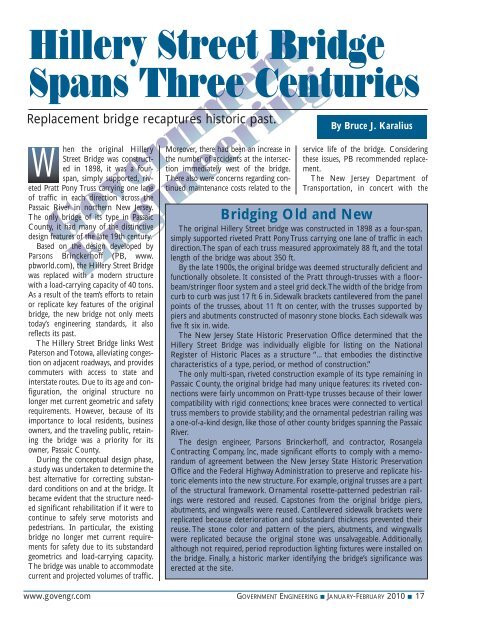
<strong>Hillery</strong> <strong>Street</strong> <strong>Bridge</strong><strong>Spans</strong> <strong>Three</strong> <strong>Centuries</strong>Replacement bridge recaptures historic past.By Bruce J. KaraliusWhen the original <strong>Hillery</strong><strong>Street</strong> <strong>Bridge</strong> was constructedin 1898, it was a fourspan,simply supported, rivetedPratt Pony Truss carrying one laneof traffic in each direction across thePassaic River in northern New Jersey.The only bridge of its type in PassaicCounty, it had many of the distinctivedesign features of the late 19th century.Based on the design developed byParsons Brinckerhoff (PB, www.pbworld.com), the <strong>Hillery</strong> <strong>Street</strong> <strong>Bridge</strong>was replaced with a modern structurewith a load-carrying capacity of 40 tons.As a result of the team’s efforts to retainor replicate key features of the originalbridge, the new bridge not only meetstoday’s engineering standards, it alsoreflects its past.The <strong>Hillery</strong> <strong>Street</strong> <strong>Bridge</strong> links WestPaterson and Totowa, alleviating congestionon adjacent roadways, and providescommuters with access to state andinterstate routes. Due to its age and configuration,the original structure nolonger met current geometric and safetyrequirements. However, because of itsimportance to local residents, businessowners, and the traveling public, retainingthe bridge was a priority for itsowner, Passaic County.During the conceptual design phase,a study was undertaken to determine thebest alternative for correcting substandardconditions on and at the bridge. Itbecame evident that the structure neededsignificant rehabilitation if it were tocontinue to safely serve motorists andpedestrians. In particular, the existingbridge no longer met current requirementsfor safety due to its substandardgeometrics and load-carrying capacity.The bridge was unable to accommodatecurrent and projected volumes of traffic.Moreover, there had been an increase inthe number of accidents at the intersectionimmediately west of the bridge.There also were concerns regarding continuedmaintenance costs related to theservice life of the bridge. Consideringthese issues, PB recommended replacement.The New Jersey Department ofTransportation, in concert with theBridging Old and NewThe original <strong>Hillery</strong> <strong>Street</strong> bridge was constructed in 1898 as a four-span,simply supported riveted Pratt Pony Truss carrying one lane of traffic in eachdirection.The span of each truss measured approximately 88 ft, and the totallength of the bridge was about 350 ft.By the late 1900s, the original bridge was deemed structurally deficient andfunctionally obsolete. It consisted of the Pratt through-trusses with a floorbeam/stringerfloor system and a steel grid deck.The width of the bridge fromcurb to curb was just 17 ft 6 in. Sidewalk brackets cantilevered from the panelpoints of the trusses, about 11 ft on center, with the trusses supported bypiers and abutments constructed of masonry stone blocks. Each sidewalk wasfive ft six in. wide.The New Jersey State Historic Preservation Office determined that the<strong>Hillery</strong> <strong>Street</strong> <strong>Bridge</strong> was individually eligible for listing on the NationalRegister of Historic Places as a structure “... that embodies the distinctivecharacteristics of a type, period, or method of construction.”The only multi-span, riveted construction example of its type remaining inPassaic County, the original bridge had many unique features: its riveted connectionswere fairly uncommon on Pratt-type trusses because of their lowercompatibility with rigid connections; knee braces were connected to verticaltruss members to provide stability; and the ornamental pedestrian railing wasa one-of-a-kind design, like those of other county bridges spanning the PassaicRiver.The design engineer, Parsons Brinckerhoff, and contractor, RosangelaContracting Company, Inc, made significant efforts to comply with a memorandumof agreement between the New Jersey State Historic PreservationOffice and the Federal Highway Administration to preserve and replicate historicelements into the new structure. For example, original trusses are a partof the structural framework. Ornamental rosette-patterned pedestrian railingswere restored and reused. Capstones from the original bridge piers,abutments, and wingwalls were reused. Cantilevered sidewalk brackets werereplicated because deterioration and substandard thickness prevented theirreuse. The stone color and pattern of the piers, abutments, and wingwallswere replicated because the original stone was unsalvageable. Additionally,although not required, period reproduction lighting fixtures were installed onthe bridge. Finally, a historic marker identifying the bridge’s significance waserected at the site.www.govengr.com GOVERNMENT ENGINEERING ■ JANUARY-FEBRUARY 2010 ■ 17
The new <strong>Hillery</strong> <strong>Street</strong> <strong>Bridge</strong> replaces the original, built in1898. The original was a four-span, simply supported, rivetedPratt Pony Truss carrying one lane of traffic in each directionacross the Passaic River in northern New Jersey.North Jersey Transportation PlanningAuthority and the FHWA, agreed tohelp fund the replacement of the bridge.However, for Passaic County to receivethe funding, several features of the originalbridge would have to be preservedor replicated as per a memorandum ofagreement between the New Jersey StateHistoric Preservation Office and theFHWA.Integrating Existing Membersand Modern MaterialsThe new bridge is a four-span, multisteelbeam superstructure with a reinforcedconcrete deck slab. The width ofthe bridge deck was increased from 17 ftsix in. to 30 ft from curb to curb, andthe load carrying capacity increasedfrom three to 40 tons. The original fiveftsix-in. sidewalk width along each sideof the bridge was retained. Roadwayimprovementswere made toreduce the incidenceof trafficaccidents. Theseincluded correctionof the poorsite distance andsubstandard turningradii at theintersectionimmediately westof the bridge byflaring the westspan of the bridgeand adding trafficsignalization tothe intersection.The new bridge was designed in accordancewith the requirements of load andresistance factor design.The superstructure is composed ofpainted W36 steel beams (AASHTOM270 Gr. 50) continuous over the fourspans. The beams are spaced at seven fteight in. on center and have a nine-in.thick reinforced high-performance concretedeck slab. The flare of the westspan was accommodated by providingdiagonal beams, which frame into the“fascia” beams. The continuous structureeliminated the need for deck joints,thereby reducing the problems associatedwith leaking joints. Reinforced elastomericbearings were installed at theabutments and piers.Six original bridge trusses that were inthe best condition were reused on threeof the four spans. Each truss consisted ofvarious members (i.e., the top and bottomchords, verticals, and diagonals),which were, themselves, composed ofindividual components (i.e., angles andplates). Even though most of the individualcomponents were only 1/4 or5/16 of an inch thick, whereby only aminor amount of corrosion could significantlyreduce the cross sectional area,about half of the members were in goodenough condition to be retained. Theother half had to be replaced with newmembers that replicated the old ones.To preserve the remaining trusses aspart of the new bridge, they were integratedinto the structural framework ofthe superstructure. The cantileveredsidewalk brackets were connected togusset plates attached to the trusses inthe same manner they were connectedin the original bridge. The gusset plateswere then attached to the fascia beam.In this manner, members of the trussstill assist in providing some load-carryingcapability.To resist moment created by the sidewalkloads on the cantilevered sidewalkbrackets, W24 steel beams were used asdiaphragms, which transform themoment from the cantilevered sidewalkinto reactions, which were then resistedby the beams. To provide rigidity, theW24 diaphragms were used throughoutthe entire framing plan and not only inthe fascia bays.The cantilevered sidewalk brackets,which are mostly composed of doubleangle components, were replaced inkind,except the thickness of the angleswas increased from 1/4 in. to 3/8 in. tomeet current state requirements. TheAt left is a view of the sidewalk brackets and lower portion of the truss on the original <strong>Hillery</strong> <strong>Street</strong> <strong>Bridge</strong>. At right, a view of thenew cantilevered sidewalk brackets from the underside of the replacement bridge.18 ■ GOVERNMENT ENGINEERING ■ JANUARY-FEBRUARY 2010 www.govengr.com
Once both abutments were relaced with new reinforced concrete abutments founded on spread footings, stone facing was attached thatreplicated the general color and appearance of the original stone .sidewalk brackets were placed at thepanel points of the trusses.The original pedestrian railings alongeach sidewalk were cleaned, repainted,and used in the same fashion on the newbridge.Drilled Shafts ReplaceOriginal PiersThe criteria to reuse the existingtrusses required the span lengths of thenew bridge to be the same as the originalbridge; hence new substructure unitsneeded to be placed at the same locationsas the original units. This requirementnecessitated complete removal ofthe existing piers and installation offour-ft diameter drilled shafts in theirplace. Accordingly, four drilled shaftswere installed at each pier. Atop each ofthe drilled shafts a cast-in-place reinforcedconcrete pier cap was constructed.The pier cap extends from just belowthe mudline to the bottom of thebeams. Stone facing was then attachedto the pier caps. Additionally, bothabutments were also removed and new,reinforced concrete abutments werefounded on spread footings.As with the piers, stone facing wasattached to the abutments and wingwalls.The stone facing was originallyintended to be fabricated with stoneblocks from the original piers and abutment.Unfortunately, since the stonewas too severely deteriorated andcracked, it could not be reused.Therefore, other stone that replicatedthe general color and appearance of theoriginal stone was used. The originalcapstones, which were composed of aharder stone than that found in the originalpiers and abutments and wingwalls,were in a condition suitable to be reusedas capstones on the new bridge piers.The new <strong>Hillery</strong> <strong>Street</strong> <strong>Bridge</strong>opened to traffic in February 2009. As aresult of careful planning, design, andconstruction, the successful replacementproject enabled the new bridge to meettoday’s transportation standards whilepreserving many elements of the historicstructure.GEMr. Karalius, P.E., is a supervising engineerand professional associate in the Princeton,NJ office of Parsons Brinckerhoff.The steel ornamentalpedestrian railing, decoratedwith a pattern of rosettes, wasin fairly good condition so itwas reused on the new bridge.The railing did require amodification because it didnot meet current geometry andsafety requirements; the railingopenings were too large. Tocorrect this condition, a steel,circular-patterned componentwas installed on the topportion of the railing to reducethe size of the opening. Thethickness of the material forthis element was minimized soas not to detract from theoverall appearance of therailing, yet functionstructurally and meet currentcode requirements.www.govengr.com GOVERNMENT ENGINEERING ■ JANUARY-FEBRUARY 2010 ■ 19