2855SU.pdf (3.92 MB) - Bayliner Parts
2855SU.pdf (3.92 MB) - Bayliner Parts
2855SU.pdf (3.92 MB) - Bayliner Parts

You also want an ePaper? Increase the reach of your titles
YUMPU automatically turns print PDFs into web optimized ePapers that Google loves.
Engine Serial Number:Hull Identification Number:Hull Identification Number• The Hull Identification Number (HIN) islocated on the starboard side of the transom.• Record the HIN (and the engine serial numbers)in the space provided above.• Include the HIN with any correspondenceor orders.TRANSOMVIEWHIN LOCATION© 2003 <strong>Bayliner</strong> Technical Publications. All rights reserved.No part of this publication may be reproduced, stored in any retrieval system, or transmitted in any form by any means, electronic, mechanical, photocopying,recording or otherwise, without prior written permission of <strong>Bayliner</strong>.Printed in the United States of America.General NotesThe material in this document is for information only and is subject to change without notice. While reasonable efforts have been made in the preparation of thisdocument to assure its accuracy, <strong>Bayliner</strong> assumes no liability resulting from errors or omissions in this document, or from the use of information containedherein.Due to our commitment to product improvement, <strong>Bayliner</strong> reserves the right to make changes in the product design, specifications, and equipment at anytime without notice or obligation. Illustrations and/or photos may show optional equipment.All <strong>Bayliner</strong> products meet or exceed USCG (Unites States Coast Guard) and/or NMMA (National Marine Manufacturer’s Association) construction standards.Manufactured with 1,1,1 Trichloroethane, a substance which harms public health and environment during the manufacturing process by destroying ozone in theupper atmosphere.Proprietary RightsThis document discloses subject matter in which <strong>Bayliner</strong> has proprietary rights. The information and design disclosed herein were originated by and are the propertyof <strong>Bayliner</strong>. Neither receipt nor possession thereof confers or transfers any right to reproduce, copy, alter or disclose the document or any part thereof, anyinformation contained therein, or to construct boats or any item from it, except by written permission from or written agreement with <strong>Bayliner</strong>. This document is tobe returned upon request to <strong>Bayliner</strong>.
Hazard Boxes & SymbolsThe hazard boxes and symbols shown below are used throughout this supplement to call attention to potentially dangeroussituations which could lead to either personal injury or product damage. Read All warnings carefully andfollow All safety instructions.!DANGER!This box alerts you to immediate hazards which WILL cause severe personal injury or death ifthe warning is ignored.! WARNING!This box alerts you to hazards or unsafe practices which COULD result in severe personalinjury or death if the warning is ignored.! CAUTION!This box alerts you to hazards or unsafe practices which COULD result in minor personalinjury or cause product or property damage if the warning is ignored.NOTICEThis box calls attention to installation, operation or maintenance information, which isimportant to proper operation but is not hazard related.FIREHAZARD!EXPLOSIONHAZARD!NO OPENFLAME!ELECTRICALHAZARD!HOTHAZARD!FALLINGHAZARD!ROTATINGPROPELLER HAZARD!RUN BILGE BLOWERSFOR 4 MINUTES!CO POISONINGHAZARD!
Chapter 1: Welcome Aboard!285 • Owner’s Manual SupplementBoating Experience!WARNING!CONTROL HAZARD!A qualified operator must be in control of the boat at all times. DO NOT operate your boatwhile under the influence of alcohol or drugs.If this is your first boat or if you are changing to a type of boat you are not familiar with, for your own comfort andsafety, obtain handling and operating experience before assuming command of the boat.Take one of the boating safety classes offered by the U.S. Power Squadrons or the U.S. Coast Guard Auxiliary.For more course information, including dates and locations of upcoming classes, contact the organizations directly:• U.S. Power Squadrons: 1-888-FOR-USPS (1-888-367-8777) or on the Internet at: http://www.usps.org• U.S. Coast Guard Auxiliary: 1-800-368-5647 or on the Internet at: http://www.cgaux.orgOutside the United States, your selling dealer, national sailing federation or local boat club can advise you of localsea schools or competent instructors.Engine & Accessories GuidelinesNOTICEWhen storing your boat please refer to your engine’s operation and maintenance manuals.• Your boat’s engines and accessories were selected to provide optimum performance and service.• Installing different engines or other accessories may cause unwanted handling characteristics.• Should you choose to install different engines or to add accessories that will affect the boat’s running trim, have anexperienced marine technician perform a safety inspection and handling test before operating your boat again.• Certain modifications to your boat will result in the cancellation of your warranty protection. Always checkwith your dealer before making any modifications to your boat.Engine & Accessories Literature• The engine and accessories installed on your boat come with their own operation and maintenance manuals.• Read and understand these manuals before using the engine and accessories.• Unless noted otherwise, all engine and accessory literature referred to in this Owner’s Manual Supplement isincluded in your owner’s packet.2
285 • Owner’s Manual Supplement Chapter 1: Welcome Aboard!Where and How CO Can AccumulateStationary Conditions That Increase CO Accumulations Include:A. Using engine,generator, orother fuelburning devicewhen boat ismoored in aconfined space.B. Mooring too close to another boat that is using itsengine, generator, or other fuel burning device.To correct stationary situations A and/or B:• Close all windows, portlights and hatches.• If possible, move your boat away from source of CO.Running Conditions That Increase CO Accumulations Include:C. Running boat with trim angle of bow too high.D. Running boat without through ventilation(station wagon effect).To correct running situations C and/or D:• Trim bow down.• Open windows and canvas.• When possible, run boat so that prevailing winds help dissipate exhaust.How to Protect Yourself and Others From CO• Know where and how CO may accumulate in and around your boat (see above).• Maintain fresh air circulation throughout the boat at all times.• Know where your engine and generator exhaust outlets are located and keep everyone away from these areas.• Never sit on, or hang onto, the back deck or swim platform while the engine(s) are running.• Never enter the areas under swim platforms where exhaust outlets are located.• Although CO can be present without the smell of exhaust fumes, if exhaust fumes are detected on the boat, takeimmediate action to dissipate these fumes.• Treat symptoms of seasickness as possible CO poisoning. Get the person into fresh air immediately. Seek medicalattention—unless you’re sure it’s not CO.• Install and maintain CO alarms inside your boat. Do not ignore any alarm. Replace alarms as recommended by thealarm manufacturer.• Follow the checklists provided on the next page.• Get a Vessel Safety Check.For information on how to get a free VESSEL SAFETY CHECK, visit www.vesselsafetycheck.org or contact yourlocal U.S. Coast Guard Auxiliary or United States Power Squadrons®.• U.S. Coast Guard Auxiliary: 1-800-368-5647 or on the Internet at: http://www.cgaux.org• U.S. Power Squadrons: 1-888-FOR-USPS (1-888-367-8777) or on the Internet at: http://www.usps.org7
Chapter 1: Welcome Aboard!285 • Owner’s Manual SupplementTrip Checklist❏ Make sure you know where the exhaust outlets are located on your boat.❏ Educate all passengers about the symptoms of CO poisoning and where CO may accumulate.❏ When docked, or rafted with another boat, be aware of exhaust emissions from the other boat.❏ Confirm that water flows from the exhaust outlet when the engines and generator are started.❏ Listen for any change in exhaust sound, which could indicate an exhaust component failure.❏ Test the operation of each CO alarm by pressing the test button.Monthly Checklist❏ Make sure all exhaust clamps are in place and secure.❏ Look for exhaust leaking from exhaust system components. Signs include rust and/or black streaking, waterleaks, or corroded or cracked fittings.❏ Inspect rubber exhaust hoses for burned, cracked, or deteriorated sections. all rubber hoses should be pliable andfree of kinks.Annual ChecklistHave a Qualified Marine Technician:❏ Replace exhaust hoses if cracking, charring, or deterioration is found.❏ Ensure that your engines and generators are properly tuned, and well maintained.❏ Inspect each water pump impeller and the water pump housing. Replace if worn. Make sure cooling systems arein working condition.❏ Inspect all metal exhaust parts for cracking, rusting, leaking, or loosening and check the cylinder head gasket,exhaust manifold, water injection elbow, and the threaded adapter nipple between the manifold and the elbow.❏ Clean, inspect, and confirm proper operation of the generator cooling water anti-siphon valve (if equipped).Carbon Monoxide Alarm System! DANGER!CARBON MONOXIDE POISONING HAZARD!DANGER• The house battery switch must be in the On position for the CO Monitorsto work.NOTICEThe stereo memory and CO monitor(s) place a small, but constant drain on the battery. If yourboat will be unattended for an extended amount of time, plug into shore power with the batterycharger turned On, or disconnect the battery if shore power is not an option.• Do not disconnect the alarm system.• Read and understand the manufacturer’s instructions for your CO alarm system. If you did not receive aninstruction manual, call (800) 383-0269 and one will be mailed to you.If your boat is not equipped with a carbon monoxide alarm, consider purchasing one from your dealer or marinesupply store.8
285 • Owner’s Manual Supplement Chapter 1: Welcome Aboard!More InformationFor more information about how you can prevent carbon monoxide poisoning on recreational boats and other ways toboat more safely, contact:United States Coast GuardOffice of Boating Safety (G-OPB-3)2100 Second Street SWWashington, DC 20593www.uscgboating.org1-800-368-5647National Marine ManufacturersAssociation (NMMA)200 East Randolph DriveSuite 5100Chicago, IL 60601-9301www.nmma.org312-946-6200American Boat & Yacht Council,Inc. (ABYC)3069 Solomon’s Island RoadEdgewater, MD 21037-1416www.abycinc.org410-956-1050For information on how to get a free VESSEL SAFETY CHECK, visit www.vesselsafetycheck.org or contact yourlocal U.S. Coast Guard Auxiliary or United States Power Squadrons®.• U.S. Coast Guard Auxiliary: 1-800-368-5647 or on the Internet at: http://www.cgaux.org• U.S. Power Squadrons: 1-888-FOR-USPS (1-888-367-8777) or on the Internet at: http://www.usps.org9
285 • Owner’s Manual SupplementChapter 2: Features / SystemsHull Exterior Hardware & DrainsFUEL TANKVENTWASTE HOLDINGTANK VENTSTORAGEDRAINWATER TANKVENTBOWEYECOCKPITDRAINSAFT BILGEPUMP DRAINFWD BILGEPUMP DRAINSHOWERSUMP DRAINHEAD SINKDRAINROPELOCKERDRAINAIR CONDITIONERDRAINAIR CONDITIONEROVERBOARDGALLEYDRAINCOCKPITDRAINSTRIM TABSTERN EYEGARBOARD DRAINTRANSOMVIEWBOARDING LADDERTRIM TABSTERN EYEMACERATOR OVERBOARDDISCHARGE (IF EQUIPPED)10
285 • Owner’s Manual Supplement Chapter 2: Features / SystemsCockpitVIEW OF AFT COCKPITAFT DECKSEATREMOVABLETABLEAFTENGINE ROOMACCESS HATCHVIEW OF AFT STARBOARD COCKPITACCESS TO FUELFILL AND WASTEPUMP-OUT HOSESCOURTESYLIGHTTRANSOMDOORCOCKPITSTORAGEAFTENGINE ROOMACCESS HATCH13
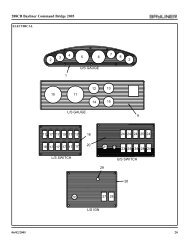
Chapter 2: Features / Systems285 • Owner’s Manual SupplementHelm LayoutHELM INSTRUMENT PANELTEMPERATUREGAUGETACHOMETERDEPTHSOUNDER(IF EQUIPPED)OILGAUGEVOLTMETERSPEEDOMETERFUELGAUGECOMPASS(IF EQUIPPED)SHIFT/THROTTLELEVER W/ TRIM &TILT SWITCHACCESSORY SWITCHES12 VOLTADAPTERVHF RADIO(IF EQUIPPED)TRIM TABSWITCHES12V DC - MAINFUSE PANEL14
285 • Owner’s Manual Supplement Chapter 2: Features / SystemsNavigation & Communication EquipmentThe owner’s packet contains instruction manuals for all navigation & communication equipment installed on yourboat. Thoroughly read and understand these manuals before using these systems. Additionally, read the warningsbelow carefully and follow all safety instructions.VHF Radio (If Equipped)Your boat may include a VHF (Very High Frequency) radio at the helm. The VHF radio can be used to accessweather reports, summon assistance or contact other vessels as permitted by the FCC (Federal CommunicationsCommission). Be sure to contact the FCC for licensing, rules and regulations concerning VHF radio usage.Compass (If Equipped)NOTICECompass accuracy can be affected by many factors. Have a qualified technician calibrate yourcompass. Make sure the technician gives you a deviation card which shows the corrections toapply in navigational calculations. Keep a copy of the deviation card at the helm.Depth Finder (If Equipped)! WARNING!• DO NOT use the depth finder as a navigational aid to prevent collision, grounding, boatdamage or personal injury.• When the boat is moving, submerged objects will not be seen until they are already underthe boat. Bottom depths may change too quickly to allow time for the boat operator to react.If you suspect shallow water or submerged objects, operate the boat at very slow speeds.15
Chapter 2: Features / Systems285 • Owner’s Manual SupplementElectrical Systems!DANGER!EXTREME FIRE, SHOCK & EXPLOSION HAZARD!• To minimize the risks of fire and explosion, NEVER install knife switches or other arcingdevices in the fuel compartments.• NEVER substitute automotive parts for marine parts. Electrical, ignition and fuel systemparts were designed and manufactured to comply with rules and regulations that minimizerisks of fire and explosion.• DO NOT modify the electrical systems or relevant drawings.• Have qualified personnel install batteries and/or perform electrical system maintenance.• Make sure that all battery switches are turned Off before performing any work in theengine spaces.!WARNING!FIRE & EXPLOSION HAZARD!• Fuel fumes are heavier than air and will collect in the bilge areas where they can beaccidently ignited.• Visually and by smell (sniff test), check the engine and fuel compartments for fumes oraccumulation of fuel.• ALWAYS run the bilge blowers for at least four minutes prior to engine starting, electricalsystem maintenance or activation of electrical devices.• Minimize the danger of fire and explosion by not exposing the batteries to open flame orsparks. NEVER smoke anywhere near the batteries.!CAUTION!SHOCK & ELECTRICAL SYSTEM DAMAGE HAZARD!NEVER disconnect the battery cables while the engine is running since it can causedamage to your yacht’s electrical system components.NOTICEElectrical connections are prone to corrosion. To reduce corrosion caused electrical problems,keep all electrical connections clean and apply a spray-on protectant that is designed to protectconnections from corrosion.16
285 • Owner’s Manual Supplement Chapter 2: Features / Systems12 Volt DC SystemFuses and Circuit Breakers• Fuses and circuit breakers for engines and mainaccessory power are on the DC main fuse paneland on the battery switch panel.• Some equipment may have secondary fuse protectionat the unit or behind the battery switch.• Electronics power is provided at the helm station.AFT DECKSTORAGEVOLTMETER12 Volt Accessory OutletsBATTERY SWITCH LOCATEDIN AFT DECK STORAGEAREA ON PORT SIDEDC MAINFUSE PANEL! CAUTION!DO NOT use the 12 volt accessory outlets with cigarette or cigar lighters. High temperaturesmay melt the outlets.Your boat is equipped with two 12 volt accessory outlets; one at the helm and one in the galley. These outlets can beused with any 12 volt device which draws 15 amps or less. The 12 volt accessory outlets are protected by 15 ampcircuit breakers on the DC main fuse panel.BatteriesThe batteries supply electricity for lights, accessories andengine starting.The Electrical section of Chapter 8, in the Cruiser &Yacht Owner’s Manual, provides battery, care andmaintenance instructions.TRANSOMAFTAlternatorsThe alternators on your engines maintain proper chargelevels of your boat’s batteries when the engine is running.ENGINECOMPARTMENTBATTERYLOCATIONSBattery Charger (If Equipped)! CAUTION!The battery charging systems (alternator and battery charger) installed on your boat aredesigned to charge conventional lead-acid batteries. Before installing gel-cell or other new technologybatteries, consult with the battery manufacturer about charging system requirements.Your boat may be equipped with a battery charger. Thoroughly read and understand the battery charger manual(provided in your boat’s owner’s packet) before using the battery charger for the first time.• The battery charger will charge the boat’s batteries whenever the boat is plugged into 120V/60Hz shore power.• For proper charging; turn the battery switch to any position except BOTH.17
Chapter 2: Features / Systems285 • Owner’s Manual SupplementBattery SwitchThe battery switch (located behindPOSITION "1"POSITION "BOTH"the helm seat in the storage area) hasACTIVATESACTIVATES BOTHBATTERY "1"BATTERIESfour (4) positions (see photograph onthe right);• Position 1 - Battery 1 providesAFT DECKpower for engine starting andSTORAGEPOSITION "2"accessories. Battery 1 (only) willACTIVATESBATTERY "2"be charged by the engine alternatorwhen the engine is running at highidle or faster.BATTERY SWITCH LOCATED• Position 2 - Battery 2 provides IN AFT DECK STORAGE"OFF"AREA ON PORT SIDEPOSITIONpower for engine starting andaccessories. Battery 2 (only) willbe charged by the engine alternatorwhen the engine is running at highBATTERY SWITCHidle or faster.• Position BOTH - If batteries are low, provides power for engine starting from both batteries. The BOTHposition also allows the charging of both batteries by the engine alternator when the engine is running at highidle or faster.• Turn the battery switch to the Off position whenever the boat will be unoccupied for long periods of time.Battery Switch PositionsBattery SwitchPositionPOSITION1POSITION2BOTHPOSITIONEngine Starting Accessories and Lights Engine Alternator Battery ChargerBattery 1Provides StartingPowerBattery 2Provides StartingPowerBOTH BatteriesProvide StartingPowerBattery 1Provides Power forAccessories and LightsBattery 2Provides Power forAccessories and LightsBOTH Batteries ProvidePower for Accessoriesand Lights (not advisedunless engine is running)ChargesBattery 1ChargesBattery 2Charges BOTHBatteriesChargesBOTHBatteriesChargesBOTHBatteriesBatteries will NOTCharge ProperlyNOTICESince the batteries on your boat were dealer-installed, the battery switch positions listed abovemay vary. Make sure you get a full explanation of battery switch use from your selling dealer.18
285 • Owner’s Manual Supplement Chapter 2: Features / SystemsShore Power/120 Volt AC System!DANGER!FIRE, EXPLOSION & SHOCK HAZARD!• DO NOT alter shore power connectors and use only compatible connectors.• Before connecting or disconnecting the shore power cord to your boat, make sure allbreakers and switches on the AC master panel are turned Off.• To prevent shock or injury from an accidental dropping of the “hot” cord into the water,ALWAYS attach the shore power cord to the boat inlet first; then to the dockside connection.When disconnecting from shore power, disconnect the shore power cord from the docksideconnection first.• NEVER leave a shore power cord connected to the dockside connection only.• Only use shore power cords approved for marine use. NEVER use ordinary indoor oroutdoor extension cords that are not rated for marine use.!WARNING!SHOCK & ELECTRICAL SYSTEM DAMAGE HAZARD!• Monitor the polarity indicator lights EVERY TIME you connect to shore power.• When connecting to shore power; if a reversed polarity light (RED colored) goes On,DO NOT energize the main breaker switches. Instead, IMMEDIATELY disconnect the shorepower cord (ALWAYS from the dockside receptacle first) and notify marina management.!WARNING!SHOCK & ELECTRICAL SYSTEM DAMAGE HAZARD!• Periodically check the shore power cord(s) for deterioration or damage. NEVER usedamaged or faulty cords since the danger of fire and electrical shock exists.• DO NOT pinch shore power cords in doors or hatches, or coil the shore power cord tootightly since these situations can generate enough heat to result in a fire.• If a shore power cord accidently becomes immersed in water, THOROUGHLY dry theblades and contact slots before reusing.!CAUTION!ELECTRICAL SYSTEM DAMAGE HAZARD!• NEVER connect dockside power to your boat outside North America unless you havepurchased the international electrical conversion equipment.• The simultaneous use of several AC components can result in an overloaded circuit. It maybe necessary to turn Off one or more accessories in order to use another accessory.• Use double insulated or three-wire protected electrical appliances whenever possible.19
Chapter 2: Features / Systems285 • Owner’s Manual Supplement!CAUTION!WATER HEATER DAMAGE HAZARD!Do not energize the water heater electrical circuit until the heater is COMPLETELY filled withwater. The tank is full if water flows from the tap when the hot water is turned On in the galley.Even momentary operation in a dry tank will damage the heating elements. Warrantyreplacements WILL NOT be made on elements or tank damaged in this manner.SINGLE SHORE POWER AC PANELNOTICESome dockside installations may be rated less than 30 amps, therefore, you may need topurchase lower amp adapters. Whenever a lower amp adapter is used, however, therewill be a corresponding drop in supplied power from the dockside system.• Single shore power 120V/60Hz, AC system feature one, 120V/30 amp, shore power receptacle.• If your boat is equipped with an air conditioning system, a second (dual) 30 amp inlet has been installed. Dualshore power inlets are labeled line 1 and line 2, which corresponds to the line 1 and line 2 master breakers on theAC panel.• The dual shore power system is designed so that each line is independent of the other except when the AC powertransfer switch is used.20
285 • Owner’s Manual Supplement Chapter 2: Features / SystemsConnecting To Shore PowerSHORE POWERINLET(S)NOTE: SINGLE INLET STANDARDDUAL INLETS WITH AIR CONDITIONER(IF EQUIPPED)TYPICAL SHOREPOWER INLETDUAL SHORE POWER AC PANEL (IF EQUIPPED)LINE 1DOCKSIDE MASTERVOLTMETERSELECTOR SWITCHVOLTMETERLINE 2TRANSFERLINE 2DOCKSIDE MASTERLINE 1POLARITYLIGHTLINE 2POLARITYLIGHT10 AMPS15 AMPS20 AMPS15 AMPS5 AMPS15 AMPS25 AMPS15 AMPSFIGURE 11. Review all hazard information at the beginning of this section, Shore Power/120V/60Hz AC System.2. Turn Off all breakers and switches on the AC master panel.3. Attach the shore power cord to the boat inlet first then to the dockside outlet.4. Monitor the AC panel’s polarity indicator lights, located below the line master breaker(s), as follows:• A green light illuminating after the power cord is plugged into the dockside outlet indicates acceptable electricalpower. You may turn On the master breaker switch.• A red light, however, indicates reversed polarity, which could cause electrical system damage and possiblyelectrical shock injuries. In this case, do not turn On the master breaker switch.21
Chapter 2: Features / Systems285 • Owner’s Manual Supplement5. Switch the "Line 1 Dockside Master" On.6. If equipped with dual dockside, switch the "Line 2 Dockside Master" On.7. Turn On the individual component breakers as required.Line 2 Transfer Switch (Dual Shore Power)NOTICE• When using the "Line 2 Transfer Switch" do not exceed 30 total amps.• The amperage of each component breaker is shown in figure 1, on the previous page.• The voltage on each line can be read by setting the voltmeter selector switch.When only one dockside outlet is available, you can use the "Line 2 Transfer Switch" to provide power to both lines.1. Connect to shore power as described in steps 1 through 4 above.2. Switch the "Line 2 Transfer Switch" On instead of the "Line 2 Dockside Master".3. Turn On the individual component breakers as required.LightingNavigation and Interior LightsRead and understand the navigation light section of the Cruiser & Yacht Owner’s Manual. The navigation andinterior lights installed on your boat are of top quality, but that they may occasionally fail for a variety of reasons:1. There may be a blown fuse - replace the fuse.2. The bulb may be burned out - carry spare bulbs for replacement.3. A wire may be damaged or may have come loose - repair as required.4. The bulb base may be corroded - clean the base and coat it with non-conductive electrical lubricant.! CAUTION!• Avoid the storage of gear where it would block navigation lights from view.• Be conservative in the use of battery power. Prolonged operation of cabin interior lights(overnight) will result in a drained battery.22
285 • Owner’s Manual Supplement Chapter 2: Features / SystemsAppliancesAll appliances installed on your boat come with their own manuals that contain instructions and importantsafeguards. Thoroughly read and understand these manuals before using your boat’s appliances.• Make sure the AC breaker is turned On for the appliance you wish to use.NOTICEAlways keep an approved ABC-type fire extinguisher in galley area.Alcohol/Electric Stove!DANGER!CARBON MONOXIDE POISONING HAZARD!• The alcohol stove is a source of dangerous carbon monoxide gas (CO).• BEFORE using the alcohol stove, Open doors and windows to make surethere is enough fresh air for ventilation.!WARNING!BURN, SCALDING & FIRE HAZARD!• Read the stove’s instruction manual before using.• Do not use the stove while underway.• Any non-cooking devices on or near your stove during use are potential fire hazards!• Do not touch burners, grates or nearby surfaces as they may be hot even when they are darkin color. Areas near burners and grates may become hot enough to cause burns.• During and after use, do not touch or let clothing or other flammable material come incontact with heated units or areas near the units (burner tops, main frame sides and back,sea rails and pot holders) until they have had enough time to cool.! CAUTION!To prevent overheating which can destroy the electric burner elements, never attempt to useboth alcohol and electric burners at the same time.23
Chapter 2: Features / Systems285 • Owner’s Manual SupplementMicrowave Oven (If Equipped)Before attempting to use the microwave oven, make sure the breaker switch on the AC master panel is On.120-Volt AC/12-Volt DC RefrigeratorYour boat features a 120-volt AC/12-volt DC refrigerator. The refrigerator runs on 12-volt DC power unless 120-voltAC power is being supplied by the generator or shore power and the AC refrigerator breaker is On.Audio EquipmentInstruction manuals for the audio equipment that may be installed on your boat, is included in your boat’s owner’spacket. Read and understand these manuals.NOTICEAM radio reception may be impaired in areas where reception is limited or anytime the engineis running.24
285 • Owner’s Manual Supplement Chapter 2: Features / SystemsPropulsionEngineThe owner’s packet contains detailed engine operation and maintenance manuals. Be sure to read and understandthese manuals before operating, or performing maintenance to, the engine.Engine AccessThe engine room can be accessed through the aft cockpit engine hatch.Engine Room Ventilation SystemThe bilge blower removes explosive fuel fumes fromthe engine compartment. Fresh air is drawn into thecompartment through the deck vents. The bilge blowerswitch is at the helm.To make sure the engine compartment is ventilated withfresh air, run the bilge blower:• For at least four minutes before starting the engine.• During starting.• Anytime your boat is running below cruising speed.BILGE BLOWERSYSTEMENGINECOMPARTMENTBLOWER HOSESTO/FROM DECKLOUVERSAFTBLOWER!WARNING!FIRE/EXPLOSION HAZARD• Use of the blower system is NOT A GUARANTEE that explosive fumes have been removed.• If you smell fuel, DO NOT start the engine and DO NOT turn On any electrical devices.• If you smell fuel and the engine is already running, shut Off the engine and tun Off allelectrical devices. Investigate immediately.• DO NOT obstruct or modify the ventilation system.25
Chapter 2: Features / Systems285 • Owner’s Manual SupplementFuel System!WARNING!FIRE/EXPLOSION HAZARD• It is very important that the fuel system be inspected thoroughly the first time it isfilled and at each subsequent filling. For your safety and the safety of your passengers,the fueling instructions in the Cruiser & Yacht Owner’s Manual must becarefully followed.! CAUTIONAvoid the storage or handling of gear near the fuel lines, fittings and tank.FUEL SYSTEM ROUTINGFUEL FILL LOCATIONFUEL FILLDECK FITTINGAFTFUEL TANKVENT FITTINGFUEL FEEDLINEAFTENGINEROOMFUEL TANKVENT FITTINGDECK FITTINGFUEL FILLFUEL TANKFuel Fill and Vent• The fuel fill fitting, marked “GAS”, is located on the starboard aft deck.• The fuel tank vent is located below the fuel fill.• If you experience difficulty filling the fuel tank, check to see if the fuel fill hose is kinked or collapsed.• If there are no visible signs of a problem, contact your local dealer.26
285 • Owner’s Manual Supplement Chapter 2: Features / SystemsFuel Filters• The fuel pickup tube (located inside the fuel tank) is equipped with a fine mesh screen filter.• In addition, when supplied by the engine manufacturer, a fuel filter is installed on the engine.• Periodically replace the fuel filters to make sure they remain clean and free of debris.• Consult with your selling dealer or local marina concerning fuel additives that help to prevent fungus or otherbuildup in your fuel tank.Anti-siphon ValveNOTICE• If an engine running problem is diagnosed as fuel starvation, check the anti-siphon valve.If the valve is stuck or clogged, change or replace it while the engine is shut down.• NEVER run the engine with the anti-siphon valve removed, except in an emergency.• Your boat is equipped with an anti-siphon valve, which is an integral part of fuel system.• The valve is located at the point where the fuel feed line attaches to the fuel tank.• The valve is spring loaded and is opened by fuel pump vacuum.• This valve will prevent fuel from siphoning from the tank in the event of a fuel line rupture.27
Chapter 2: Features / Systems285 • Owner’s Manual SupplementQuick Oil Drain SystemQUICK OIL DRAIN SYSTEMTRANSOMOIL DRAIN HOSEGARBOARDDRAIN PLUGOIL DRAIN PLUGENGINE OIL PANDRAWCORDBILGEGARBOARDDRAINTo drain the engine oil:1. Remove the boat from the water.2. Unscrew the garboard drain plug.3. Pull the draw cord until the oil drain plug and the oil drain hose slide out of the garboard drain.4. Place the end of the oil drain hose into a suitable container.5. Unscrew the oil drain plug and drain the engine oil.6. Replace the oil drain plug.7. Push the drain hose back into the bilge.8. Replace the garboard drain plug.Always dispose of waste oil in accordance with local regulations.28
285 • Owner’s Manual Supplement Chapter 2: Features / SystemsControlsSTEERINGCABLESHIFT/THROTTLECABLESSHIFT/THROTTLELEVERPower Trim and TiltThe stern drive on your boat is equipped with power trim and tilt.Trim and tilt instructions are provided in the engine operation manual and the shifter/throttle manual, included inyour owner’s packet.29
Chapter 2: Features / Systems285 • Owner’s Manual SupplementTrim TabsVIEW OF HELMTRIM TAB SWITCHTRIM TABCOMPONENTSTRANSOMTRIM TAB(TYPICAL)!WARNING!LOSS OF CONTROL HAZARD!Improper use of trim tabs will cause loss of control!• Do not allow anyone unfamiliar with trim tabs to use them.• Do not use trim tabs in a following sea as they will cause broaching or other unsafe handlingcharacteristics.• Do not use trim tabs to compensate for excessive unequal weight distribution.The trim tabs may be used to help keep your boat level at cruising speeds. The trim tabs are controlled by two rockerswitches at the helm. Before using the trim tabs read and understand the trim tab operation manual included in yourboat’s owner’s packet.Observe the following:• Once cruising speed is reached, the port or starboard trim switch may be used (one at a time) to level the boat.• Perform trim tab adjustment with several short touches to the switch rather than one long one.• After each short touch allow several seconds for the hull to react.• The trim tab hydraulic fluid reservoir is located in the engine compartment. The fluid level must be checkedperiodically (at least once a year) and refilled as necessary.30
285 • Owner’s Manual Supplement Chapter 2: Features / SystemsBilge PumpsTHE AFT BILGE PUMP IS LOCATED UNDER THE ENGINETHE FORWARD BILGE PUMP IS LOCATED UNDER THE ENTRY STEPSAFTAFT BILGE PUMP& FLOAT SWITCHTHRU-HULLFWD BILGE PUMP& FLOAT SWITCHYour boat is equipped with two automatic impeller-type bilge pumps which are used to pump water out of the bilge.Bilge pumps are controlled by automatic bilge pump float switches (autofloat switches) and/or switches at the helm.Bilge pumps are wired directly to the battery so they will normally function even when the boat is completely shutdown and left unattended.NOTICEDischarge of oil, oil waste or fuel into navigable waters is prohibited by law. Violators aresubject to legal action by the local authorities.31
Chapter 2: Features / Systems285 • Owner’s Manual SupplementBilge Pump TestingBilge pumps are critical to the safety of your boat. Check the bilge pumps often to make sure they are working.Individually test each pump as follows:1. Turn On bilge pump switch at helm.2. Make sure water in bilge is pumped overboard.If there is water in the bilge and the pump motor is running but notpumping inspect the discharge hose for a kink or collapsed area.If no problems are found, check the bilge pump housing for cloggingdebris as follows:1. Remove power cartridge:a. Lift tab while rotating fins counter-clockwise.b. Lift out power cartridge.c. Clear outer housing of debris.2. Reinstall power cartridge:a. Make sure “O” ring is properly seated.b. Coat “O” ring with a light film of vegetable or mineral oil.c. Align two cams on either side of power cartridge with twoslots on outer housing and press power cartridge into housingwhile twisting clockwise.3. Check reinstallation by trying to twist fins counter-clockwisewithout lifting tab; cartridge should stay in place.BILGE PUMPCOMPONENTSLIGHTFILMOF OILTAB“O” RINGPOWERCAMCARTRIDGE(TYPICAL)FINOUTERHOUSINGSLOT (TYPICAL)Autofloat SwitchesAutomatic bilge pumps use electromagnetic float (autofloat) switches to turn On the pump whenever water risesabove a preset level in the bilge. One autofloat switch is mounted next to each automatic bilge pump. Autofloatswitches are wired directly to the battery and will normally function even when the boat is completely shut down andleft unattended.Test the autofloat switches often as follows:FLOAT SWITCH TESTING1. Push float switch test button up to turnOn bilge pump.FLOAT SWITCHTEST BUTTONIf the pump does not turn on, check theinline fuse. If the fuse is good but the switchdoes not work, it may indicate a bad switchor possibly a low battery.2. Push test button all the way down toreturn the float switch to auto mode.FLOAT UP - TEST MODEBILGE PUMP SHOULD TURN ONFLOAT DOWN - AUTO MODEBILGE PUMP SHOULD TURN OFF! CAUTION!When the test is completed on each float switch, you MUST push the test button all the waydown to the auto position to return the switch to auto mode!32
285 • Owner’s Manual Supplement Chapter 2: Features / SystemsFreshwater Systems (If Equipped)WATER TANK FILLLOCATIONVIEW OF GALLEYGALLEYFAUCETWATER TANKFILL FITTINGPUMPSWITCHYour boat may feature a pressure-demand freshwater (potable) system. This system works when the water pumpswitch in the galley is in the On position.• The water pump’s DC breaker must be turned On for the freshwater system to work.• Inspect and clean the water filter, located on the water pump, often.• The water tank is located in the engine room, on the port side.• The water tank fill fitting is located on the starboard deck.• Drain the freshwater system in winter months and when not in use to prevent damage and to keep stored waterfrom becoming stagnant and distasteful.• If the freshwater system needs to be disinfected, ask your dealer about treatments available for your boat’s system.Transom ShowerYour boat is equipped with a freshwater transom shower. It is locatedinside the transom storage area (see illustration on the right). The waterpump switch must be turned On before using the transom shower. Besure to read the manufacturer’s instructions, provided in your boat’sowner’s packet.PORTTRANSOM STORAGE AREATRANSOMSHOWERTRANSOMSTORAGE33
Chapter 2: Features / Systems285 • Owner’s Manual SupplementWater Heater (If Equipped)HOT HAZARD!!WARNING!Water heated by the water heater can reach temperatures hot enough to scald the skin.!CAUTION!WATER HEATER DAMAGE HAZARDS!• DO NOT energize the AC water heater electrical circuit until the heater is completely filledwith water. Even momentary operation in a dry tank will damage the heating elements.Warranty replacements will not be made on elements or tank damaged in this manner.The tank is full if water flows from the tap when the hot water is turned On in the galley.• The water heater should be drained and the power turned Off when the possibility offreezing exists.• The water heater is located on the port side of the engine compartment.• The water heater is connected to the AC power system, therefore, you must make sure that the water heaterbreaker on the AC panel is turned On before water will be heated.• Read the manufacturer’s instruction manual supplied in your boat’s owner’s packet and observe thewarnings above.COLD WATER LINE ROUTINGFROM WATER TANKWATER LINETO WATERHEATERWATER LINETO HEADWATER TANKFILL FITTINGWATER TANKVENT FITTINGWATERTANKWATERHEATERPUSH TO RESETCIRCUIT BREAKER(UNDER METAL COVER)FITTING FORCOLD WATERLINEFITTING FORHOT WATERLINEAFT BILGE HOT WATER LINE ROUTING(COLD IS TYPICAL)WATERHEATERWATER LINETO GALLEYWATER LINETO HEADWATERPUMPWATER LINETO TRANSOMSHOWERAFTFWDWATER LINEFROM TANKWATER PUMP AND WATERTANK ACCESS BELOWMIDDLE ENTRY STEP34
285 • Owner’s Manual Supplement Chapter 2: Features / SystemsSink & Shower Drain SystemsGray water (water from sinks and showers) above the waterline is gravity drained overboard, while gray water belowthe waterline is pumped overboard using a sump pump.DCBAEAThe sump box (A, above), containing the shower sump pump, float switch, and filter is located under the middleentry step (B).Sump Box CleaningPeriodically clean the sump box, filter, and pump as follows:1. Remove the cover screws (C) and the cover (D).2. Remove any debris from the box and the filter.3. Clean the sump pump as outlined in the bilge pump section of this Supplement.Sump System WinterizationDrain the sump pump system in the winter months when not in use.1. Disconnect and drain all lines to the unit.2. Remove the screws from the mounting feet (E) and drain the system.3. Reinstall the screws in the mounting feet and reconnect the system.35
Chapter 2: Features / Systems285 • Owner’s Manual SupplementSeawater SystemsSeacocks• A seacock is a valve that is used to manage the pickup of seawaterthrough the hull and below the water line.• Seacocks are controlled by a 90º lever and are used on theseawater pickup systems for the air conditioning system andmarine head (toilet) system.• Before using any of these systems, make sure that the system’sseacock is Open and remains in the Open position until thesystem is shut Off.90 DEGREESEACOCKLEVERHULLSECTIONSEAWATER PICKUP VALVE (SEACOCK)COMPONENTS (TYPICAL)SEACOCK (TYPICAL)SEACOCK GASKETPICKUP STRAINER!CAUTION!SYSTEM DAMAGE HAZARD!• Before using a seawater pickup system, make sure that the system’s seacock is in the Openposition before the system is started and keep the seacock Open until the system is shut Off.• Close seacocks whenever the systems will not be used for long periods of timeSeawater StrainersSeawater strainers are used in water pick-up systems to filter incoming seawater. The typical layout is one strainer forthe marine head and one for the air conditioning system (if equipped).Seawater strainers are located near the system’s seawater pickup valves (seacocks). Check for leaks and/or debrisevery time you use your boat. If debris is found, clean the seawater strainer as follows:1. Make sure the component/system that the strainer is connected to is turned Off.2. Close the pickup seacock that sends seawater to the strainer you are about to clean. The seacock must remainClosed until the strainer is completely reassembled.3. Take apart the seawater strainer.4. Remove debris.5. Reassemble the seawater strainer.6. Open the seacock before turning on the component or system.!CAUTION!FLOODING HAZARD!• The pickup seacock that sends seawater to the strainer must be closed before disassemblingthe seawater strainer to prevent the boat from taking on water through the seawaterstrainer assembly. Keep the pickup seacock closed until the seawater strainer is completelyreassembled.SYSTEM DAMAGE HAZARD!• After reassembling the seawater strainer, make sure that the pickup seacock is Open beforeusing the component/system.36
Chapter 2: Features / Systems285 • Owner’s Manual SupplementMacerator (If Equipped)To use the macerator to pump waste directly into the water(where regulations permit):1. Open the underwater discharge seacock located in theengine compartment on the starboard transom.2. Press both macerator switches at the same time to runthe pump.3. Close the underwater discharge seacock when you aredone pumping.MACERATOR SYSTEM (IF EQUIPPED)FWDOVERBOARDDISCHARGESEACOCKFROM TANK TOMACERATORMACERATORHOLDINGTANKNOTICECheck with local authorities for regulations regarding the legal use of marine head systems.38
285 • Owner’s Manual Supplement Chapter 2: Features / SystemsAir Conditioning System (If Equipped)!DANGER!CARBON MONOXIDE POISONING HAZARD!Dangerous carbon monoxide gas (CO) can be brought into the yacht throughthe air conditioning system.!CAUTION!SYSTEM DAMAGE HAZARD!The air conditioning system’s seacock must be Opened before turning on the air conditionerand must remain Open during operation.VIEW OF PORT SIDE OF BILGEVIEW OF FORWARD BERTH BUNK TOPAIR CONDITIONERPICKUPHOSE TO AIRCONDITIONERAIR CONDITIONERCONTROLSAIR CONDITIONERWATER PUMPAIR CONDITIONEROVERFLOWAIR CONDITIONERSEAWATER STRAINERAIR CONDITIONERSEAWATER PICKUPAIR CONDITIONEROVERBOARDSUMPPUMPAFTFROMPICKUPAIRCONDITIONERUNITYour boat may be equipped with an air conditioning system. Read the air conditioner manual, included in yourowner’s packet, before using the air conditioning system.• Before using the air conditioning system, make sure the breakers on the AC main distribution panel are turned Onand make sure the system’s seawater pickup seacock is Open The seacock must remain Open anytime the airconditioner is in use.• The seawater pickup strainer should be checked for debris according to the directions given in the SeawaterStrainer section of this Supplement.39
Chapter 2: Features / Systems285 • Owner’s Manual SupplementCanvas Top (If Equipped)! CAUTION!Take down and securely stow the convertible top, side curtains and back cover beforetransporting your boat by road.GDEIKKFBHJCKADC1. Slide the swivel ends (A) of the main bow (B) over the side windshield frames (C) and insert the pins (D).2. Unfold the canvas top (E) and slide the swivel ends of the forward legs (F) over the windshield frames and insertthe pins.3. Slide the eye ends (G) of the aft legs (H) into the deck hinges (I) on the radar wing (J) and insert the pins4. No adjustments to the bow jaw slides (K) should need to be made as they are preset during manufacturing.Before attempting to adjust the jawslide positions, obtain the correct measurements from your selling dealer40
285 • Owner’s Manual SupplementChapter 3: Electrical RoutingsHull Wire Harness RoutingsGROUNDBUSS BARENGINEHARNESSBONDINGBUSS BARTRIMTAB PUMPAIR CONDITIONER WATERPUMP (IF EQUIPPED)BLOWERBATTERY CHARGERDC PANELIN GALLEYFUEL TANKSENDERSHOWERSUMP PUMPMACERATORAFTBILGEPUMPTOSWITCHPANELFORWARDBILGEPUMPREFRIGERATORAIR CONDITIONER& SUMP PUMP(IF EQUIPPED)NOT USEDTO DASHHARNESSIN DECK41
Chapter 3: Electrical Routings285 • Owner’s Manual SupplementDeck Wire Harness RoutingsNOTE: VIEWS ARE UNDERSIDE OF DECKSTO AFT DECKDASHOVERHEADLIGHTWIPERSTEP LIGHTOVERHEADLIGHTSTO GALLEYLIGHTSLIGHT SWITCHCOMPASSOVERHEADLIGHTFORWARD DECKOVERHEADLIGHTNAVIGATIONLIGHTSAFT DECKRADAR WING PLUGSIDE PANEL & SHIFTER PLUGSTARBOARDCOURTESY LIGHTOVERHEADLIGHTSAFTPORTCOURTESY LIGHT42
285 • Owner’s Manual Supplement Chapter 3: Electrical RoutingsBattery Cable RoutingsPOSITIVE BATTERY CABLE ROUTINGSBATTERY SWITCHIN TRANSOM STORAGESTARTERSOLENOIDON ENGINEJUMPERCABLEPOSITIVECABLESBATTERIESAFTNEGATIVE BATTERY CABLE ROUTINGSGROUNDBUSS BARENGINEGROUNDBATTERIESNEGATIVEJUMPERCABLEAFT43
285 • Owner’s Manual SupplementChapter 4: Wiring DiagramsAC Electrical System, Single Dockside44
285 • Owner’s Manual Supplement Chapter 4: Wiring DiagramsAC Electrical System, Dual Dockside45
Chapter 4: Wiring Diagrams285 • Owner’s Manual SupplementGas Engine Electrical System46
285 • Owner’s Manual Supplement Chapter 4: Wiring DiagramsDiesel Engine Electrical System47
285 • Owner’s Manual SupplementImportant RecordsSelling DealerKey NumbersName Of DealershipIgnitionOtherAddressPhone/FAX/E-mailElectronicsSales ManagerManufacturerModel Name/NumberService ManagerSerial NumberEngineManufacturerModel Name/NumberSerial NumberManufacturerModel Name/NumberEngine Serial NumberManufacturerModel Name/NumberOil Type/SAE Quarts per Engine Filter TypeSerial NumberPropellerManufacturerModel Name/NumberManufacturerPitchSerial NumberModel Number48
285 • Owner’s Manual SupplementFloat PlanBefore going boating, fill out a copy of this float plan (or similar) and leave it with a reliable person whom you candepend on to contact the Coast Guard or other rescue organization, if you do not return as scheduled.Description of BoatPersons on BoardRegistration/Documentation NumberFull NameLength Make TypeAge Health Phone NumberHull ColorTrim ColorFull NameFuel Capacity Engine Type Number of EnginesAge Health Phone NumberDistinguishing FeaturesDistinguishing FeaturesFull NameAge Health Phone NumberOperator of BoatFull NameFull NameAge Health Phone NumberMale or Female Age HealthAddressAddressFull NameAge Health Phone NumberPhone/FAX/E-mailFull NameOperator’s ExperienceAge Health Phone Number49
Float Plan285 • Owner’s Manual SupplementSurvival EquipmentTrip ExpectationsMarine Radio (Yes/No) Type FrequenciesDeparting FromNumber of PFDs Flares (Yes/No) Mirror (yes or no)Departure DateDeparture TimeSmoke Signals (Yes/No) Flashlight (Yes/No) Food (Yes/No)Stopover 1Water (Yes/No) Anchor (Yes/No) Raft/Dinghy (Yes/No)Arrive No Later Than: DateArrive No Later Than: TimePaddles (Yes/No) EPIRB (Yes/No) OtherOther Other OtherStopover 2Arrive No Later Than: DateArrive No Later Than: TimeVehicle DescriptionStopover 3MakeModelArrive No Later Than: DateArrive No Later Than: TimeColorLicense NumberWhere is the Vehicle Parked?Stopover 4Arrive No Later Than: DateArrive No Later Than: TimeStopover 5Arrive No Later Than: DateArrive No Later Than: TimeStopover 6Arrive No Later Than: DateArrive No Later Than: TimeFinal Destination Port (If Different Than Home Port)Arrive No Later Than: DateArrive No Later Than: TimeIf not returned by the date and time listed above, callthe Coast Guard or other local authority.Coast Guard Phone NumberLocal Authority Phone Number50
Owner’s Notes
Owner’s Notes
Part Number 1700674<strong>Bayliner</strong> • P.O. Box 9029 • Everett, WA 98206 • 360-435-5571