4614 Air damper actuators GMA...1
4614 Air damper actuators GMA...1
4614 Air damper actuators GMA...1

Create successful ePaper yourself
Turn your PDF publications into a flip-book with our unique Google optimized e-Paper software.
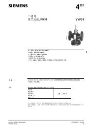
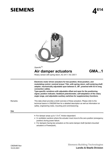
4 614Open<strong>Air</strong> TM<strong>Air</strong><strong>damper</strong><strong>actuators</strong>Rotary version with spring return, AC 24 V / AC 230 V<strong>GMA</strong>..<strong>.1</strong>Electronic motor driven <strong>actuators</strong> for two-position, three-position, andmodulating control, nominal torque 7 Nm, with spring return, self-centering shaftadapter, mechanically adjustable span between 0...90°, prewired with 0.9 m longconnection cables.Type-specific variations with adjustable offset and span for the positioningsignal, position indicator, feedback potentiometer, self-adaptation of the rotaryangle range, and adjustable auxiliary switches for supplementary functions.RemarksThis data sheet provides a brief overview of these <strong>actuators</strong>. Please refer to thetechnical basics in CM2Z<strong>4614</strong>en for a detailed description as well as information onsafety, engineering notes, mounting and commissioning.Use• For <strong>damper</strong> areas up to 1.5 m 2 , friction-dependent.• In ventilation sections where the actuator must move to the zero position (emergencyposition) during power failure.• For <strong>damper</strong>s having two <strong>actuators</strong> on the same <strong>damper</strong> shaft (tandem-mounted<strong>actuators</strong> or Powerpack).CM2N<strong>4614</strong>en16.03.2001Siemens Building TechnologiesLandis & Staefa Division
Type summary<strong>GMA</strong>... 121<strong>.1</strong>E 126<strong>.1</strong>E 321<strong>.1</strong>E 326<strong>.1</strong>E 131<strong>.1</strong>E 132<strong>.1</strong>E 136<strong>.1</strong>E 161<strong>.1</strong>E 163<strong>.1</strong>E 164<strong>.1</strong>E 166<strong>.1</strong>E 191<strong>.1</strong>E 194<strong>.1</strong>EControl type Two-position control Three-position controlOperating voltageAC/DC 24 VModulating controlStandard version Enhanced vers.X X X X X X X X X X XOperating voltageAC 230 VX XPositioning signal YDC 0..<strong>.1</strong>0 V X X X XDC 2..<strong>.1</strong>0 VXDC 0...35 V withcharacteristic function Uo, ∆UX X XPosition indicatorU = DC 0..<strong>.1</strong>0 VX X X X X XFeedback potentiometer 1kΩXSelf-adaptation ofrotary angle rangeAuxiliary switches (two) X X X X X XRotary direction switch X X- Powerpack (2 <strong>actuators</strong>) X X X X X X X X X- Master/slave control X XXXFunctionsType <strong>GMA</strong>12.<strong>.1</strong> / <strong>GMA</strong>32.<strong>.1</strong> <strong>GMA</strong>13.<strong>.1</strong> <strong>GMA</strong>16.<strong>.1</strong> / <strong>GMA</strong>19.<strong>.1</strong>Control type Two-position control Three-position control Modulating controlPositioning signal with adjustablecharacteristic functionRotary directionSpring returnPosition indication: MechanicalPosition indication: ElectricalAuxiliary switchSelf-adaptation ofrotary angle rangePowerpack (two <strong>actuators</strong>, tandemmounted)DC 0...35 V atOffsetUo = 0...5 VSpan∆U = 2...30 VClockwise or counter-clockwise movement depends on the mounting position of the <strong>damper</strong> shaft……and on the type ofcontrol.For <strong>GMA</strong>19.<strong>.1</strong> only:…and on the DIL switch setting that is eitherclockwise or counter-clockwise.On power failure or when the operating voltage is switched off,the spring return moves the actuator to its mechanical zero position.Rotary angle position indication by using a position indicator.The feedbackpotentiometer can beconnected to externalvoltage to indicate theposition.Output voltage U = DC 0..<strong>.1</strong>0 V is generatedproportional to the rotary angle.For <strong>GMA</strong>19.<strong>.1</strong> only: U depends on the rotarydirection of the DIL switch setting.The switching points for auxiliary switches A and B can be set independent of each otherin increments of 5° within 5° to 90°.For <strong>GMA</strong>19…1 only: When self-adaptation isactive, the actuator automatically determines themechanical end positions of the rotary angle rangeand maps the characteristic function (Uo, ∆U) tothe calculated rotary angle range.Mounting two of the same actuator types on thesame <strong>damper</strong> shaft may result in a double torque.Only for <strong>GMA</strong>19.<strong>.1</strong>:Parallel operation of the <strong>actuators</strong> by master/slavecontrol.Rotary angle limitation The rotational angle of the shaft adapter can be limited mechanically at increments of 5°.OrderingNotePotentiometer and auxiliary switches cannot be added in the field. For this reason,order the type that includes the required options.2/4Siemens Building Technologies <strong>Air</strong> <strong>damper</strong> <strong>actuators</strong> <strong>GMA</strong>..<strong>.1</strong>, rotary version with spring return CM2N<strong>4614</strong>enLandis & Staefa Division 16.03.2001
DeliveryAccessories, sparepartsIndividual parts such as position indicator and other mounting materials for the actuatorare not mounted on delivery.Accessories to functionally extend the <strong>actuators</strong> are available, e.g., linear/rotary setsand weather protection cover; see data sheet N4697.Technical dataAC/DC 24 V supply(SELV/PELV)AC 230 V supplyFunction dataPositioning signal for <strong>GMA</strong>13.<strong>.1</strong>Positioning signal for <strong>GMA</strong>16.<strong>.1</strong>,<strong>GMA</strong>19.<strong>.1</strong>Characteristic functionsfor <strong>GMA</strong>161<strong>.1</strong>, 166<strong>.1</strong>, 191<strong>.1</strong>for <strong>GMA</strong>163<strong>.1</strong>, 164<strong>.1</strong>, 194<strong>.1</strong>Position indicatorfor <strong>GMA</strong>16.<strong>.1</strong>, 19.<strong>.1</strong>Feedback potentiometerfor <strong>GMA</strong>132<strong>.1</strong>Auxiliary switchfor <strong>GMA</strong>..6<strong>.1</strong>, 164<strong>.1</strong>, 194<strong>.1</strong>Connection cablesDegree of protection of housingProtection classEnvironmental conditionsStandards and directivesDimensionsWeightOperating voltage AC / FrequencyOperating voltage (DC)Power consumption <strong>GMA</strong>1..<strong>.1</strong>: Running<strong>GMA</strong>12.<strong>.1</strong>, 13.<strong>.1</strong>: Holding<strong>GMA</strong>16.<strong>.1</strong>, 19.<strong>.1</strong>: HoldingOperating voltage / FrequencyPower consumption <strong>GMA</strong>32.<strong>.1</strong>: RunningHoldingNominal torqueMaximum torque (blocked)Nominal rotary angle / Max. rotary angleRuntime for rotary angle 90° (motor operation)Closing time with return spring (on power failure)Switching current (at AC/DC 24 V) for "Open"/"Close" (cores 6,7)Input voltage Y (wires 8-2)Max. permissible input voltageInput voltage Y (wires 8-2)Non-adjustable characteristic functionAdjustable characteristic functionOffset UoSpan ∆UOutput voltage U (cores 9-2)Max. output currentChange of resistance (wires P1-P2)LoadContact ratingVoltage (no mixed operation AC 24 V / AC 230 V)Switching range for auxiliary switches / Setting incrementsCross-sectionStandard lengthDegree of protection as per EN 60 529 (note mounting instructions) IP 54Insulation classAC/DC 24 V, feedback potentiometerAC 230 V, auxiliary switchOperation / TransportTemperatureHumidity (non-condensing)Product safety: Automatic electrical controls forhousehold and similar useElectromagnetic compatibility (EMC):Immunity for all models, except <strong>GMA</strong>132<strong>.1</strong>xImmunity for <strong>GMA</strong>132<strong>.1</strong>xEmissions for all modelsConformity: Electromagnetic compatibilityLow voltage directiveConformity: Australian EMC FrameworkRadio Interference Emission StandardActuator W x H x D (see "Dimensions")Damper shaft: Round / squareMin. shaft lengthAC 24 V ± 20 % / 50/60 HzDC 24 V ± 15 %AC:5VA/3.5W //DC:3.5WAC/DC: 2 WAC/DC: 2.5 WAC 230 V ± 10 % / 50/ 60 Hz7VA/4.5W3.5 W7Nm21 Nm90° / 95° ± 2°90 s15 snormally 8 mADC 0..<strong>.1</strong>0 V / DC 2..<strong>.1</strong>0 VDC 35 VDC 0...35 VDC 0..<strong>.1</strong>0 V / DC 2..<strong>.1</strong>0 VDC 0...5 VDC 2...30 VDC 0..<strong>.1</strong>0 VDC ± 1mA0..<strong>.1</strong>000 Ω
Internal diagrams<strong>GMA</strong>12.<strong>.1</strong> / <strong>GMA</strong>32.<strong>.1</strong> <strong>GMA</strong>13.<strong>.1</strong> <strong>GMA</strong>16.<strong>.1</strong>, <strong>GMA</strong>19.<strong>.1</strong>Two-position control Three-position control Modulating controlAC/DC 24 V AC 24 V...230 V / 6 (2) ADC 0..<strong>.1</strong>0 V / 2..<strong>.1</strong>0 V / 0...35 V<strong>GMA</strong>12... 1 S1 S4(G)(Q11)(Q21)MA B(G0)(Q12)(Q14)(Q22)(Q24)<strong>4614</strong>G022 S2 S3 S5 S6AC 230 V AC 24 V...230 V / 6 (2) A<strong>GMA</strong>32... 3 S1 S4(L)(Q11)(Q21)AC/DC 24 VAC 0 V(Y2)0..<strong>.1</strong>000 Ω AC 24 V...230 V / 6 (2) A<strong>GMA</strong>13... 6 7 P1 P2 P3 S1 S4(Y1)M(G)(G0)(a)(b)(c)100%0%A(Q12)(Q14)1 2S2 S3 S5 S6AC/DC 24 V(Q11)B(Q22)(Q21)(Q24)<strong>4614</strong>G04AC/DC 24 V DC 0..<strong>.1</strong>0 V AC 24 V...230 V / 6 (2) A<strong>GMA</strong>16.<strong>.1</strong><strong>GMA</strong>19.<strong>.1</strong> 1 8 S1 S4(G)M(G0)(Y)100%0%(U)DC 0..<strong>.1</strong>0 VA(Q12)(Q11)(Q14)(Q22)(Q24)2 9 S2 S3 S5 S6B(Q21)<strong>4614</strong>G01MAB(N)(Q12)(Q14)(Q22)(Q24)4 S2 S3 S5 S6<strong>4614</strong>G03Cable labelingCablePin Code No. ColorMeaningAbbreviationActuators AC 24V G 1 red RD System potential AC/DC 24 VDC 24 V G0 2 black BK System neutralY1 6 purple VT Pos. signal AC 0 V/ AC/DC 24 V, openY2 7 orange OG Pos. signal AC 0 V / AC/DC 24 V, closeY 8 gray GY Pos. signal DC 0..<strong>.1</strong>0 V, 2..<strong>.1</strong>0 V, 0...35 VU 9 pink PK Output DC 0..<strong>.1</strong>0 VActuators L 3 brown BR Phase AC 230 VAC 230 V N 4 blue BU Neutral conductorAuxiliary switch Q11 S1 gray/red GY RD Switch A InputQ12 S2 gray/blue GY BU Switch A Normally closed contactQ14 S3 gray/pink GY PK Switch A Normally open contactQ21 S4 black/red BK RD Switch B InputQ22 S5 black/blue BK BU Switch B Normally closed contactQ24 S6 black/pink BK PK Switch B Normally open contactPositioner a P1 white/red WH RD Potentiometer 0..<strong>.1</strong>00 % (P1-P2)b P2 white/blue WH BU Potentiometer pick-offc P3 white/pink WH PK Potentiometer 100...0 % (P3-P2)Dimensions141113<strong>GMA</strong>..<strong>.1</strong>4210.6 20Dia.5Dia. 6.4...20.5Square 6.4..<strong>.1</strong>3608131.5Dia<strong>.1</strong>0.516818019192 60TaptiteM6 x 16122Mounting bracket1530303Dimensions in mm<strong>4614</strong>M01en4/4ã2000 Siemens Building Technologies Ltd.Subject to changeSiemens Building Technologies <strong>Air</strong> <strong>damper</strong> <strong>actuators</strong> <strong>GMA</strong>..<strong>.1</strong>, rotary version with spring return CM2N<strong>4614</strong>enLandis & Staefa Division 16.03.2001