Cooper-Wheelock RSS-RSSP Series - Gamewell-FCI
Cooper-Wheelock RSS-RSSP Series - Gamewell-FCI
Cooper-Wheelock RSS-RSSP Series - Gamewell-FCI
- No tags were found...

Create successful ePaper yourself
Turn your PDF publications into a flip-book with our unique Google optimized e-Paper software.
General Notes• Strobes are designed to flash at one flash per second minimum over Regulated Voltage Range. Note that NFPA-72(1999) specifies a flash rate of one to two flashes per second and ADA guidelines specify a flash rate of one to threeflashes per second.• All candela ratings represent minimum effective strobe intensity based on UL Standard 1971.• <strong>Series</strong> <strong>RSS</strong> & <strong>RSS</strong>P Strobe products are listed under UL Standard 1971 for indoor use with a temperature range of32°F to 120°F (0°C to 49°C) and maximum humidity of 93% (± 2%).• “Regulated Voltage Range” is the newest terminology used by UL to identify the voltage range. Prior to this, UL used theterm “Listed Voltage Range”.Table 1: Average RMS Current*<strong>RSS</strong>/<strong>RSS</strong>P24VDCModels<strong>RSS</strong>/<strong>RSS</strong>P - Wall Mount<strong>RSS</strong> - Ceiling Mount24MCW 24MCWH 24MCC 24MCCH15 cd 30 cd 75 cd 110 135 185 15 cd 30 cd 75 cd 95 cd 115 177cd cd cdcd cd16VDC24VDC33VDC0.101 0.062 0.102 0.192 0.265 0.300 0.420 0.068 0.112 0.211 0.292 0.300 0.4200.064 0.041 0.062 0.116 0.155 0.195 0.270 0.045 0.072 0.128 0.171 0.195 0.2700.047 0.032 0.047 0.081 0.107 0.145 0.190 0.035 0.052 0.089 0.118 0.145 0.190<strong>RSS</strong>/<strong>RSS</strong>P24VDCModels2415-75W1575cd<strong>RSS</strong>/<strong>RSS</strong>PWallMount12157-5W* Average RMS Current is per UL average RMS method and Average Mean Current is per UL averagemean method. 12 volt models use Average Mean Current.For rated inrush and peak current across the UL Listed voltage range for both filtered DC and unfilteredVrms (FWR), see installation instructions.8 VDC 0.33612VDC17.5VDC0.1790.136Table 2: Audible/Speakers forSYNC Modules<strong>RSS</strong>P Strobe PlateProduct<strong>Series</strong>Multitone Appliances AMT, MTHornsAH, NH, HSModelNumberOrderCodeInputVoltage(VDC)AverageMeanCurrent@ 24VDCMountingOptionsMotor BellsMB-G6/G10SM-12/24-R 6369 24 0.028 WSpeakers ET-1010/1080, E70,ET70ChimesCH70DSM-12/24-R 6374 24 0.035 WSM Sync Module is rated for 3.0 amperes @ 24 VDC DSMSync Module is rated for 3.0 amperes per circuit.The maximum number of interconnected DSM modules is 20.GAMEWELL-<strong>FCI</strong>12 Clintonville Road, Northford, CT 06472 - Tel: (203) 484-7161 - Fax: (203) 484-7118www.gamewell-fci.com 9020-0575 Rev. B1 page 2 of 4
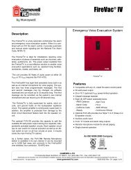
WIRING DIAGRAMSFROMPRECEDINGAPPLIANCE,SYNC MODULE,POWER SUPPLYOR FACPSERIES <strong>RSS</strong>/<strong>RSS</strong>P APPLIANCESNON-SYNCHRONIZED+ -TO NEXTAPPLIANCEOR EOLRSERIES <strong>RSS</strong>/<strong>RSS</strong>P APPLIANCES SYNCHRONIZEDWITH SM MODULESINGLE CLASS "B" NAC CIRCUITFACPSTROBENACCIRCUITSM+ STROBE- STROBE+ AUDIBLEEOLR- AUDIBLE<strong>RSS</strong><strong>RSS</strong>+ -+ -SERIES <strong>RSS</strong>/<strong>RSS</strong>P APPLIANCES SYNCHRONIZEDSERIES <strong>RSS</strong>/<strong>RSS</strong>P APPLIANCES SYNCHRONIZEDWITH DSM MODULESINGLE CLASS "A" NAC CIRCUITFACPSTROBENACCIRCUITOUTSTROBENACCIRCUITRETURN+ SYNC- SYNCDSM+ OUT 1+ IN 1MINUS 1+ AUDIBLE- AUDIBLEMINUS 2+ IN 2+ OUT 2<strong>RSS</strong> <strong>RSS</strong> <strong>RSS</strong><strong>RSS</strong><strong>RSS</strong><strong>RSS</strong>FACPWITH MUTIPLE DSM MODULESSTROBENACCIRCUITSTROBENACCIRCUITSTROBENACCIRCUITDSM #1+ SYNC- SYNCDSM #2+ SYNC- SYNCDSM #3+ SYNC- SYNC<strong>RSS</strong><strong>RSS</strong><strong>RSS</strong>DSM INTERCONNECTING WIRING SHOWN.MAXIUMUM OF TWENTY (20) MODULES<strong>RSS</strong><strong>RSS</strong><strong>RSS</strong>STROBE/PLATE ASSEMBLYAUDIBLE & VISIBLE APPLIANCEOPERATE IN UNISONFROMPRECEDINGAPPLIANCE,SYNC MODULE,POWER SUPPLYOR FACP+ -+ -+ -STROBE+ -APPLIANCETO NEXTAPPLIANCEOR EOLRFROMPRECEDINGAPPLIANCEOR FACPFROMPRECEDING-APPLIANCE,SYNC MODULE,POWER SUPPLYSTROBE/PLATE ASSEMBLYAUDIBLE & VISIBLE APPLIANCEOPERATE INDEPENDENTLY+-+OR FACP + -STROBE+ -APPLIANCE+-+-TO NEXTAPPLIANCEOR EOLRTO NEXTSTROBEOR EOLRGAMEWELL-<strong>FCI</strong>12 Clintonville Road, Northford, CT 06472 - Tel: (203) 484-7161 - Fax: (203) 484-7118www.gamewell-fci.com 9020-0575 Rev. B1 page 3 of 4
Architects and Engineers SpecificationsThe visual notification appliances shall be <strong>Cooper</strong>-<strong>Wheelock</strong> <strong>Series</strong> RS strobe appliances or approved equals. The<strong>Series</strong> <strong>RSS</strong> shall be Listed under UL Standard 1971 (Emergency Devices for the Hearing Impaired) for Indoor FireProtection Service. The strobe shall be listed for indoor use and shall meet the requirements of FCC Part 15 Class B.The strobe appliances shall produce a flash rate of one (1) flash per second over the Regulated Voltage Range andshall incorporate a Xenon flashtube enclosed in a rugged Lexan® lens.The <strong>Series</strong> <strong>RSS</strong> shall be of low current design. Where multi-candela appliances are specified, the strobe intensityshall have a minimum of four (4) field selectable settings and shall be rated per UL Standard 1971 at: 15, 30, 75, and110 cd, or 135/185 cd for wall mount, or 15, 30, 75, and 95cd or 115/177 cd for ceiling mount. The selector switch forselecting the candela shall be tamper resistant. The 15/75 candela strobe shall be specified when 15 cd UL Standard1971 Listing with 75 cd on-axis is required (e.g. ADA compliance).When synchronization is required, the appliance shall be compatible with <strong>Cooper</strong>-<strong>Wheelock</strong>’s SM and DSM SyncModules. The strobes shall not drift out of synchronization at any time during operation. If the sync module fails tooperate, (i.e. contacts remain closed), the strobe shall revert to a non-synchronized flash rate. The appliance shallalso be designed so that the audible signal may be silenced while maintaining strobe activation.The <strong>Series</strong> <strong>RSS</strong> Strobe appliances shall incorporate a patented universal mounting plate that allows mounting on asingle-gang, double-gang, 4-inch square, 100 mm European type backbox, or the SHBB surface backbox. If required,an NATP (Notification Appliance Trimplate) shall be provided. An attaching cover plate shall be provided to give theappliance an attractive appearance. The appliance shall not have any mounting holes or screw heads visible whenthe installation is complete.The <strong>Series</strong> <strong>RSS</strong>P Multi-Candela or single candela Strobe Plate shall be mounted on either a standard 4-inch squarebackbox for flush mounting, or the <strong>Wheelock</strong> SBL2 backbox for surface mounting. All notification appliances shall bebackward compatible.Specifications and Ordering InformationModelOrderCodeWallMountCeilingMountNon-SyncSync w/SM orDSMStrobeCandela 24 VDC 12VDC# ModelColorRed# ModelColorWhiteSquareor RoundUL MEA CSFM FM<strong>RSS</strong>-24MCW-FR 9400 X — X X 15/30/75/110 X — X — Square X X X X X<strong>RSS</strong>=241575W-FR 7471 X — X X 15 (75 on Axis) X — X — Square X X X X X<strong>RSS</strong>-121575W-FR 7476 X — X X 15 (75 on Axis) — X X — Square X X X X X<strong>RSS</strong>-24MCC-FW 3158 — X X X 15/30/75/95 X — — X Square X * * * *<strong>RSS</strong>-24MCCR-FW 3159 — X X X 15/30/75/95 X — — X Round X * * * *<strong>RSS</strong>-24MCCH-FW 3461 — X X X 115/177 X — — X Square X * * * *<strong>RSS</strong>-24MCCR-FW 3463 — X X X 115/177 X — — X Round x * * * *<strong>RSS</strong>-24MCWH-FR 3465 X X X 135/185 X X Square X * * * *<strong>RSS</strong>WP-2475W-FR 9013 X — X X 75 @ -31°F X — X — Square X X X X *<strong>RSS</strong>P-121575W-FR 7798 X — X X 15 (75 on Axis) — X X — Square X X X X X<strong>RSS</strong>P-24MCW-FR 9402 X — X X 15/30/75/110 X — X — Square X X X X X<strong>RSS</strong>P-241575W-FR 7793 X — X X 15 (75 on Axis) — — x — Square X X X X X<strong>RSS</strong>P-24MCWH-FR 9482 X X X 135/185 X X Square X * * * *# Models are available in either red or white. * PENDINGBFPGAMEWELL-<strong>FCI</strong>12 Clintonville Road, Northford, CT 06472 - Tel: (203) 484-7161 - Fax: (203) 484-7118www.gamewell-fci.com 9020-0575 Rev. B1 page 4 of 4