MAX® 5510 PRO ACRegenerator - Panamax!
MAX® 5510 PRO ACRegenerator - Panamax!
MAX® 5510 PRO ACRegenerator - Panamax!

You also want an ePaper? Increase the reach of your titles
YUMPU automatically turns print PDFs into web optimized ePapers that Google loves.
MAX®<strong>5510</strong> <strong>PRO</strong> <strong>ACRegenerator</strong> Owner’s ManualPOWERMAX® <strong>5510</strong> <strong>PRO</strong> <strong>ACRegenerator</strong>MODEL M<strong>5510</strong>-<strong>PRO</strong>1690 Corporate Circle, Petaluma CA 94954 • www.panamax.com
MAX®<strong>5510</strong> <strong>PRO</strong> <strong>ACRegenerator</strong> Owner’s ManualThank you for purchasing this MAX® <strong>5510</strong>Pro, <strong>ACRegenerator</strong>! You now own oneof the finest line conditioning and powerprotection products on the market today.Over 25 years of power protection experienceand more than 10 years ofAudio/Video noise filtration experiencewere utilized during the development ofthis model. The MAX® <strong>5510</strong> Pro hasbeen specifically engineered to enhancethe performance and life expectancy ofhigh-end Audio/Video entertainment gear.The combination of our sophisticatedpower conditioning and the world’s finestpower protection has resulted in anAudio/Video power center that meets thepower quality needs for each piece ofequipment in your entertainment system.This is truly a Firewall for Noise!With power this clean, your audio/videoor home theater system will finally beable to perform up to its full capabilities.Performance alone makes this a worldclassproduct but we didn’t stop there;its styling complements and completeseven the most sophisticated Audio/Videoshowcase.POWERMAX® <strong>5510</strong> <strong>PRO</strong> <strong>ACRegenerator</strong>MODEL # M<strong>5510</strong>-<strong>PRO</strong>PANAMAX, the <strong>Panamax</strong> logo and MAX are registered US trademarks of <strong>Panamax</strong>.<strong>ACRegenerator</strong>, Firewall for Noise, SurgeGate Plus, Protect or Disconnect and SignalPerfect are trademarks of PANAMAX.SIDACtor is a registered US trademark of Teccor Electronics, Inc. TiVo is a trademark of TiVo, Inc.
POWERTABLE OF CONTENTSBefore You Begin.........................................................1Introduction.................................................................2Connection Diagram....................................................3Feature Overview.........................................................4Feature DetailsAnalog Voltmeter & Ammeter.................................5Convenience Outlet................................................5Diagnostic Lights...................................................5Sequential Startup/Shutdown................................6High-Current Outlet Bank......................................6Isolated Switched Outlet Bank................................6Filtered Outlet Banks 1 and 2..................................7AV Signal Lline Protection......................................7Convenience Lamp................................................7Voltage Sense Triggers..........................................7Isolation Transformer Circuit Breaker.....................8Coaxial Line Protection..........................................8Telephone Line Protection......................................8AC Surge Protection..............................................8SurgeGate Plus Protection..................................9Automatic Over & Under Voltage Protection..........9Technical Specifications...............................................9RS-232 Command Specification................................10Isolated vs. Balanced Power.......................................11Troubleshooting.........................................................12BEFORE YOU BEGINIn addition to this owner’s manual, items included with the MAX® <strong>5510</strong>-<strong>PRO</strong> package are:MAX® 510 <strong>PRO</strong> <strong>ACRegenerator</strong>1 - MAX®<strong>5510</strong>-<strong>PRO</strong>2 - Rack ears w/ screws forrack mounting option1 - RJ-11 Telephone Cable1 - LED Convenience Lamp1 - CAT 5 Ethernet Cable3 - Coax Cables forSatellite TV, Cable TVand/or Antennas1 - IEC 320, 120V/15Adetachable power cordPlease verify that you have received all these items. If not, contact <strong>Panamax</strong>.USA & Canada (800) 472-5555 • (707) 283-5900 • Fax (707) 283-59011
INTRODUCTIONYour Audio/Video components are constantlybeing bombarded by electromagnetic interference(EMI) and radio frequency interference (RFI)through their power cords. This contaminatedpower can affect analog and digital equipment andwill degrade the overall performance of your entiresystem. Digital components can also introducenoise on their AC power lines, which can interferewith the performance of analog components.Common symptoms of contaminated powerinclude pops, hisses, hums, visual artifacts, etc.Most power filtering devices will remove some ofthis interference but don’t provide a comprehensivesolution to the problem.The MAX® <strong>5510</strong> Pro’s Power Filtration System isthe Complete Solution!Level 1 - for Digital Source Components orDisplay Devices:True isolation from contaminated power sources isthe first level. The heart of the MAX® <strong>5510</strong> Pro isa 720VA, Isolation Transformer that providespower to four outlets for your digital source componentsor displays. AC Regeneration throughelectromagnetic coupling between the primary andsecondary windings of the transformer allows onlyclean, pure AC power to reach your equipment.None of the EMI/RFI contamination gets past theisolation transformer! In addition, any noise generatedby your digital source components is isolatedand prevented from reaching the rest of yourequipment through their power cords.Two different power modes, Isolated andBalanced, are available as output from the isolationtransformer. These are selected with the frontpanel AC Regeneration pushbutton. In the Isolatedmode, the secondary (load side) of the transformer’swinding is completely isolated fromground connections. Digital source components(with 2-blade power plugs) that are plugged intothese outlets are also isolated, eliminating groundloops and hum.In the Balanced mode, a center tap wire from thesecondary winding is connected to ground. Thiscreates a balanced voltage waveform (+60V Line-Ground & -60V Neutral-Ground, 180 degrees outof phase), which still provides 120VAC to yourequipment but has the benefit of canceling anycommon mode noise between Line/Neutral andGround.The MAX® <strong>5510</strong> Pro allows you to switch betweenIsolated and Balanced modes since there is no wayto categorically state that “Isolated Power” is betterthan “Balanced Power” or that “BalancedPower” is better than “Isolated Power”. Bothmodes provide clean, regenerated power to yourdigital source components. One setting may providebetter results than the other for your particularsystem but the only way to really know is to tryboth and use the one that sounds better to you.Results will depend upon the quality of yourincoming power, noise sources close to your homeor system, your combination of components andthe quality and routing of interconnected cabling.Due to this, different results may be observedwhen comparing picture and sound quality fromidentical equipment in different physical locations.Level 2 – for Analog Components:The second level in the Power Filtration systemfeatures two banks of independently filtered outlets(2 outlets per bank) for your analog components.These outlet banks utilize “Balanced DoubleL” filter circuits which are far superior to any otherdesign in filtering out all forms of electromagneticand radio frequency interference in both commonand normal modes. Cross-contamination betweenyour components is also eliminated with thisdesign.Level 3 – for High-Current Components:The third level of the system specifically addressesthe unique power requirements of current hungrycomponents such as amplifiers and poweredsubwoofers. These components rapidly drawlarge amounts of current to replenish their capacitorsafter thunderous bass notes. Line conditionersthat utilize coils (inductors) in series with theAC power line can “choke” off this large in-rushcurrent, thereby reducing the amplifiers’ ability tooperate at peak performance levels, resulting in aflat, dead sound. The MAX® <strong>5510</strong> Pro’s high-currentoutlets are fed by noise filtration circuitry thatdoes not utilize coils and provides full, unimpededpower for your amplifiers and powered subwoofers.Other Convenience Features Enhance theFunctionality:Although the MAX® <strong>5510</strong> Pro’s functionalityrevolves around noise filtration and power protection,many other exciting features enhance youroverall entertainment experience, including:• An analog, backlit voltmeter indicates the AC linevoltage coming into your system.• An analog, backlit ammeter shows the actualcurrent draw of all your connected components,giving a visual reference as to how your system isfunctioning under a variety of conditions.• A front panel pushbutton controls the meterlighting intensity (High, Low, Off) and color (Blueor Amber).• A detachable rear panel LED convenience lampsimplifies system setup in low-light situations.• An Always-On, convenience outlet on the frontpanel is for temporary AC connections.As you read through the rest of this manual, you’lldiscover many more unique features. As hometheater enthusiasts, we care about the quality ofyour listening and/or viewing experience. Ourgoals are to:• Make power better (conditioning that allows yoursystem to perform up to its full capabilities)• Make power safer (protect your investment fromdamaging power disturbances)• Enhance the pleasure you get from your A/V systemThank you for choosing <strong>Panamax</strong> for your powerquality needs. Please finish reading the instructions,install the MAX® <strong>5510</strong> Pro and enjoy the fullpotential of your entertainment system.21690 Corporate Circle, Petaluma CA 94954 • www.panamax.com
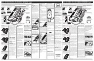
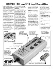
TRIGGERDELAYHIGH CURRENTOUTLETS DELAYSWITCHEDOUTLETS DELAYTRIGGERDELAYHIGH CURRENTOUTLETS DELAYISOLATEDOUTLETS DELAYVIDEOAUDIOAUDIOVIDEOVIDEOCONNECTION DIAGRAMSTEP 1Typical AC Power, RS232 and 12V Trigger ConnectionsAMPLIFIERDVDHOME AUTOMATIONCONTROLCD PLAYERAUDIO VIDEO RECEIVER<strong>PRO</strong>PERLYGROUNDEDAC OUTLETCIRCUITBREAKERGROUNDLUGHIGH CURRENTOUTLETSISOLATED OUTLETSALWAYS ON OUTLETSCIRCUITBREAKERRS-23212V TRIGGERIN OUTAC INLET LINE EQUIPControlUSBLEDLIGHTTRIGGERENABLELINE LEVEL AUDIO / VIDEOOUT OUT OUT OUT OUTIN IN IN IN INR G B H VLAN / TELCOSATELLITE 1SATELLITE 2CATV / ANTTVSUBWOOFERVCRSATELLITE RECEIVERPVR (TiVo)STEP 2Basic Signal Line ConnectionsVIDEO <strong>PRO</strong>JECTOR**Remote componentspowered fromdifferent AC circuitsDUAL LNBSATELLITE DISHTVCIRCUITBREAKERGROUNDLUGHIGH CURRENTOUTLETSISOLATED OUTLETSALWAYS ON OUTLETSCIRCUITBREAKERRS-23212V TRIGGERIN OUTAC INLET LINE EQUIPControlUSBLEDLIGHTTRIGGERENABLELINE LEVEL AUDIO / VIDEOOUT OUT OUT OUT OUTIN IN IN IN INR G B H VLAN / TELCOSATELLITE 1IN OUTSATELLITE 2IN OUTCATV / ANTIN OUTDVDPVR (TiVo)AUDIO VIDEO RECEIVERPHONEJACKCATVSATELLITE RECEIVERAUDIOAUDIOUSA & Canada (800) 472-5555 • (707) 283-5900 • Fax (707) 283-5901 3
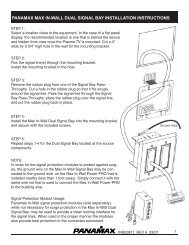
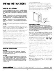
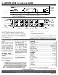
FEATURE OVERVIEW1. Power Switch and LED:Pushbutton; activates a turnonor shutdown sequence forthe Isolated and High-Currentoutlets. The Green LED willbe illuminated when the unit isplugged into an AC outlet andthe power switch is in the“ON” position. The LED flashesduring the outlet turn-onand turn-off delay periods.2. Meter Lights Switch:Pushbutton; controlsbrightness of the Ammeterand Voltmeter backlighting.Cycles among five settings;High Blue, Low Blue, HighAmber, Low Amber, OFF3. LED Indicators:Switched Outlets, VoltageTrigger, Unsafe Voltage,Isolated Power andBalanced Power statusindicators.4. AC RegenerationControl and LEDIndicators:Select either IsolatedPower Mode andBalanced Power Modefor your digital sourcecomponents or videodisplay device5. Ammeter:Backlit analog metermeasures currentdraw for connectedequipment.6. Voltmeter:Backlit analog metermeasures incomingvoltage source from0-150 VAC.7: Convenience Outlet:Provides a quick convenientway to plug in componentssuch as camcorders and videogame systems.POWERMAX® <strong>5510</strong> <strong>PRO</strong> ACRenerator1. 15A Main CircuitBreaker: Opens in theevent that equipmentplugged into the MAX5500 draws too muchcurrent. When white isvisible, the breaker hasopened. Reduce theload and push to reset.2. High Current OutletBank: Two delayed outletsdesigned for high currentcomponents such asamplifiers and poweredsubwoofers. The currentavailable to connectedequipment is not limitedby the noise filtrationcomponents.3. Isolated (Switched)Outlets: Four outlets providecomplete isolation for digitalsource components such asDVD players or display deviceslike plasma TVs or DLPprojectors. These outlets arecompletely isolated from therest of the system.4. Filtered Outlet Banks1& 2: Four, Always-On,Balanced Double L filteredoutlets for low current analogaudio components suchas pre-amplifiers, receivers,VCR's and tape decks. Twooutlets per filter bank.5. Isolated OutletsCircuit Breaker:Opens in the event thatequipment connectedto the IsolationTransformer Outletsexceeds 6 amps currentdraw. When whiteis visible, the breakerhas opened. Reducethe load and push toreset.6. RS232ControlInterface: DB-9male connector.Use to connect theM<strong>5510</strong>-Pro to ahome automationsystem.7. LampReceptacle:USB jack. Theconveniencelamp includedwith theM<strong>5510</strong>-Pro isto illuminatethe rear panelsof other componentsduringsetup.8. Line LevelAudio/Video Jacks: ColorcodedRCA jacks, female, 5pair. Use to protect the mainsystem from backdoor surgescoming in on the signal lines.9. Satellite Coax Jacks:Two pairs of F-Connectorsoptimized for Satellite TVsignal line protection.MAIN BREAKERHIGH CURRENT OUTLETS ISOLATED OUTLETS ALWAYS ON OUTLETSISOLATED OUTLETS BREAKERLINE LEVEL AUDIO / VIDEOSATELLITE 1OUTOUTOUT OUT OUTGROUNDRS232 CONTROLUSBLEDLIGHTINOUTSATELLITE 212V TRIGGERIN OUTTRIGGERENABLETRIGGERDELAY-ONIN IN IN IN INR G B H VLAN / TELCOHC SWITCHEDOUTLETS OUTLETSDELAY DELAYINCATVOUTIEC 320 C13 120V/15AINOUT10. IEC MainPower Receptacle:Detachable power cordconnects to this receptacle.11. Ground Lug: Providesa common grounding pointfor equipment with separateground leads12. DC Trigger Input:3.5mm (1/8”) Mini-Plugjack. Connect to aremote trigger device thatuses a DC voltage signalto initiate a startup/shutdownsequence.13. DC Trigger Output:3.5mm (1/8”) Mini-Plug jack.The M<strong>5510</strong>-Pro can generate itsown 12VDC trigger to controlanother device.14. TriggerEnable Switch:Enables or disablesthe DC Triggerinput function.16. Trigger DelaySwitch: Sets thedelay time (0 or 10seconds) betweenreceiving a DC triggerinput signal and whenthe M<strong>5510</strong>-Pro sendsits DC Trigger outputsignal.15. High-Current Outlet Delay Switch:3-position slide switch. Allows adjustment of theTurn-On delay for the 2 Delayed High CurrentOutlets. Choose between 0 and 10 seconds.17. IsolatedOutlets DelaySwitch: 3-positionslide switch. Allowsadjustment of theTurn-Off delay forthe 4 IsolationTransformer Outlets.Choose between“always-on”, and10 seconds.19. CATV Coax Jacks:One pair of F-Connectorsoptimized for Cable TV,Antenna or Cable Modemsignal line protection.18. LAN/Telephone Jacks:In/Out connections for Ethernet,telephone line or pay-per-viewline protection.4 1690 Corporate Circle, Petaluma CA 94954 • www.panamax.com
POWERPOWERMAX® <strong>5510</strong> <strong>PRO</strong> ACReneratorMAX® <strong>5510</strong> <strong>PRO</strong> ACReneratorFEATURE DETAILSThe indicators are:Power Switch and LED Indicator: MomentaryPushbutton (non-locking); activates a turn-on orshutdown sequence for the Isolated (Switched) andHigh-Current outlet banks. The Green LED will beilluminated when the unit is plugged into an ACoutlet and the power switch is in the “ON” position.Switched Outlets: Green LED. This light indicatesthe status of the Isolated (Switched) and High-Current outlet banks. When the LED is ON, both outletbanks are on and providing power. When the LEDis OFF, the power to these two outlet banks is alsoOFF.Press and hold the button >2 seconds to turn theHigh Current and Isolated outlet banks On/Off.Voltage Trigger: Green LED. This light indicatesstatus of the DC voltage trigger.If the unit is already on and the power button ispressed quickly (< 2 seconds), the High Current andIsolated Outlet banks are turned Off, then back On(sequenced according to the delay settings). Thisprevents accidentally turning the connected equipmentOff and provides an easy method of cyclingpower to reboot components that may lock up.Meters: The analog meters are backlit to providethe ability to view readings in a dark room. LEDs(light emitting diodes) are used in order to providedurability and long life.The Voltmeter samples the incoming voltage fromthe wall outlet and provides a visual representation ofthe available power. The Voltmeter is Always-On andindicates the incoming line voltage even during anunsafe voltage condition. Readings above 150V willnot be accurate due to the meter’s damping characteristics.The Ammeter measures the amount of currentbeing drawn by the connected equipment and theM<strong>5510</strong>-Pro. The Ammeter needle will fluctuate asmusic or movie soundtracks call upon the amplifiersto reproduce thunderous bass notes. During anunsafe voltage condition, the Ammeter will continuemeasuring the amount of current being drawn by theMax <strong>5510</strong>-Pro, but since all of the connected equipmenthas been disconnected by the protection circuitry,the needle will be only slightly above zero.Meter Lighting: The front panel pushbuttoncontrols the meter lighting and cycles among fivesettings; High Blue, Low Blue, High Amber, LowAmber, OFFDiagnostic Indicator Lights: The MAX <strong>5510</strong>-Prois loaded with special features to save your connectedequipment from many different forms of dangerouspower disturbances. Diagnostic lights on thefront panel inform you in the event of either a powerdisturbance or when a special feature is activated.MAX® <strong>5510</strong> <strong>PRO</strong> ACReneratorWhen enabled by the rear-panel switch and a DCvoltage is sensed by the input trigger circuitry, thisLED turns ON along with the switched outlets. Boththe LED and the outlets will be OFF when the DCvoltage trigger is not receiving a signal.When disabled by the rear-panel switch, the LED willremain ON and front-panel power switch will controlthe On/Off status of the switched outlets.Unsafe Voltage: Red LED. Under normal voltageconditions, this light stays off. When this light isflashing slowly (once every 2 seconds), it indicatesan under-voltage or over-voltage condition. Whenthe light is flashing quickly (twice per second), itindicates a 10 second recovery period from anunder/over-voltage condition. This LED will flashquickly when the MAX <strong>5510</strong>-Pro is first plugged into the wall outlet.AC Regeneration Control: Pushbutton switchused for selecting the power supply mode for thedigital source components. One of the adjacentLEDs for Isolated Power and Balanced Power willilluminate to indicate the active switch position.Isolated Power: Green LED. When this light isON, it indicates that the Isolated Power Mode hasbeen selected for the power supply to theIsolated/Switched Outlets.Balanced Power: Green LED. When this light isON, it indicates that the Balanced Power Mode hasbeen selected for the power supply to theIsolated/Switched Outlets.Convenience Outlet: A single outlet on the frontpanel of the Max <strong>5510</strong>-Pro provides an easy-toreachpower source for electronic equipment typicallyused on a part time basis. Such equipment includesanything from video game systems to camcorders.Do not use this outlet for household appliances likevacuum cleaners!The convenience outlet provides clean, protectedpower for your sensitive electronic equipment. Thisoutlet is Always-On and will continually supply asteady source of power. It is important to rememberthat power will be disconnected only in the event ofan unsafe voltage condition.USA & Canada (800) 472-5555 • (707) 283-5900 • Fax (707) 283-5901 5
MAIN BREAKERIEC 320 C13 120V/15AMAIN BREAKERIEC 320 C13 120V/15AISOLATED OUTLETS BREAKERTRIGGERENABLETRIGGERDELAY-ONOUTLINE LEVEL AUDIO / VIDEOOUTOUT OUT OUTIN IN IN IN INR G B H VLAN / TELCOHC SWITCHEDOUTLETS OUTLETSDELAY DELAYIIINFEATURE DETAILS (continued)Sequential Startup/Shutdown:Isolated/Switched Outlet Bank:Complex audio/video systems may be susceptibleto voltage transients generated internally at startup/shutdownif all of the equipment is powered onor off at the same time. This can cause speaker“thumps” which are not only annoying but can alsodamage the speakers. The MAX <strong>5510</strong>-Pro isdesigned to eliminate these transients by providinga “start-up” delay for the High Current outlets and a“shutdown” delay for the switched IsolationTransformer Outlets. This allows the componentsplugged into the switched outlets to power-up andstabilize before any amplifiers and powered subwoofersare turned on. This sequence is reversedduring shutdown. The amplifiers and powered subwoofersturn off, their power supplies drain, and thenthe equipment plugged into the switched outlets isturned off.Information on setting the delay times is included inthe Isolated/Switched Outlets and High CurrentOutlets sections that follow.GROUNDHIGH CURRENT OUTLETSISOLATED OUTLETSFour outlets (one bank of four) are fed power throughthe heart of the MAX <strong>5510</strong>-Pro, the IsolationTransformer. These outlets should be used for digitalcomponents such as DVD players or display deviceslike Plasma TVs or DLP projectors.Pure, clean power is obtained by using the isolationtransformer to regenerate the AC current. The powerfrom a typical wall outlet is contaminated with electromagnetic(EMI) and radio frequency (RFI) interference(noise) picked up by the power lines betweenthe power utility’s generating plant and the wall outlet.This contaminated power feeds the isolationtransformer's primary windings and is regenerated(through electromagnetic induction) as clean poweron the isolated secondary windings. The outlets areconnected to the secondary windings, which have nophysical connection to the primary windings. This isTrue Isolation! Not only will it isolate your digitalsource equipment from contaminated power, but alsoprevent any noise generated in the digital componentsfrom flowing back to other connected equipment.GROUNDHIGH CURRENT OUTLETSISOLATED OUTLETSHigh-Current Outlet Bank:The two high-current outlets allow amplifiers andpowered subwoofers to work to their full potential.When the movie thunders with a terrific explosion orwhen the music reaches a climactic crescendo, anamplifier has to rapidly draw large amounts of currentto replenish its capacitors. Traditional line conditionersimpede this current draw, in effect, starvingan amplifier and resulting in a flat, dead sound. TheHigh-Current Outlet Bank provides clean, filteredpower to amplifiers but has no current limitingcomponents to impede performance.The high current outlets are designed with a turn-ondelay option of 0 or 10 seconds. The 2-position,HC Outlet Delay switch on the back of the MAX<strong>5510</strong>-Pro is used to select the desired time delay.When a delay is selected, the high-current outletswill turn-on after the Isolated/switched outlets andturn-off before the Isolated/switched outlets (if they’renot set to always-on). With a delay, the connectedequipment will not power up simultaneously, thuspreventing loudspeaker noises such as “thumping”.OUTLETSRS232 CONTROL12V TRIGGERIN OUTUSBLEDLIGHTA 2-position slide switch (Switched OutletsDelay) located on the rear panel controls the timingfor the Isolation Transformer Outlets. Together, theseoutlets can be set as “always-on” or with a turn-offdelay of 10 seconds to prevent speaker “thump”.This switch provides the option of having a total ofeight always-on outlets (4 Filtered Outlets and 4Isolation Transformer Outlets).When set to the 10 second delay position, theIsolation Transformer Outlets will remain as Switchedoutlets, controlled by the Power pushbutton and/orthe DC Voltage Sense Trigger. In this situation, theIsolation Transformer Outlets will not power downuntil after the selected time delay has elapsed.Two different power modes, Isolated and Balanced,are available as output from the isolation transformer.These are selected with the front panel ACRegeneration pushbutton. In the Isolated mode,the secondary (load side) of the transformer’s windingis completely isolated from ground connections.Digital source components (with 2-blade powerplugs) that are plugged into these outlets are alsoisolated, eliminating ground loops and hum.In the Balanced mode, a center tap wire from the secondarywinding is connected to ground. This createsa balanced voltage waveform (+60V Line-Ground & -60V Neutral-Ground, 180 degrees out of phase),which still provides 120VAC to your equipment buthas the benefit of canceling any common mode noisebetween Line/Neutral and Ground.6USA & Canada (800) 472-5555 • (707) 283-5900 • Fax (707) 283-5901
GROUNDALWAYS ON OUTLETSMAIN BREAKERIEC 320 C13 120V/15AHIGH CURRENT OUTLETS ISOLATED OUTLETS ALWAYS ON OUTLETSISOLATED OUTLETS BREAKERRS232 CONTROLUSBLEDLIGHTOUTLINE LEVEL AUDIO / VIDEOOUT OUT OUT OUTIN IN IN IN INR G B H V12V TRIGGERLAN / TELCOIN OUTHC SWITCHEDTRIGGER TRIGGER OUTLETS OUTLETSENABLE DELAY-ON DELAY DELAYSATELLITE 1INOUTSATELLITE 2INOUTCATVINOUTFEATURE DETAILS (continued)Circuit Breakers:OUTOUT OUT OUTINOUTTelephone/LAN Line Protection:SATELLITE 2SATELLITE 1VIDEOOUT OUTINOUTSATELLITE 2IN ININOUTH VCATVN / TELCOINOUTSATELLITE 1LINE LEVEL AUDIO / VIDEOOUT OUT OUT OUTINOUTSATELLITE 2IN IN IN ININOUTG B H VCATVLAN / TELCOSWITCHEDOUTLETSDELAYINOUTSATELLITE 1LINE LEVEL AUDIO / VIDEOOUT OUT OUT OUTINOUTSATELLITE 2IN IN IN ININOUTG B H VCATVLAN / TELCOSWITCHEDOUTLETSDELAYINOUTThere are two separate circuit breakers on the backpanel of the MAX <strong>5510</strong>-Pro. The main circuitbreaker will trip only if the total current drawexceeds the maximum current rating (15A). Thismeans that collectively, all outlets must draw morethan 15 Amps before the circuit breaker will trip.There is also a 6 Amp circuit breaker to protectthe 720 VA Isolation Transformer and its circuitry.The Isolation Transformer provides pure power fordigital source components, which require very littlecurrent to operate at peak performance.Please note: Do not plug high-poweredamplifiers or powered subwoofers into theIsolation Transformer Outlets. Their currentrequirements may exceed the 6 Amp limitand cause the circuit breaker to trip.Coaxial Line Protection:All coaxial cable sheaths from outdoors mustbe grounded to the building grounding electrodesystem where they enter the building(per applicable NEC/CEC code). A drivenground rod is not adequate.<strong>Panamax</strong>'s exclusive SignalPerfect Technologyprovides application specific protection for yoursatellite and cable TV equipment. The satelliteconnections are for coaxial cables connected to aDBS (single or dual LNB) satellite dish. The CATVconnection is for a non-amplified rooftop antenna orcable TV line. Alternatively, it may be used to protectthe equipment plugged into the MAX <strong>5510</strong>-Pro from"backdoor" surges in situations where the videosignal is run to another room for a 2nd television.Cable TV (Including HDTV) & Cable Modems:TV tuners operate at approximately 500 millivolts(1/2 volt) and utilize the frequency spectrum of 50MHz to 950 MHz. Digital cable boxes and cablemodems typically operate at slightly higher voltageswhile cable modems utilize the frequency rangebelow 50 MHz. The clamping level of the MAX<strong>5510</strong>-Pro's CATV protection circuitry is 1400 millivolts(1.4 volts). The circuitry is shielded to preventinterference and has been optimized to have less than1dB of signal loss throughout the entire frequencyrange up to 950 MHz.Satellite TV: Satellite dish LNB's can require up to24 volts to operate and utilize the frequency range of950 MHz to 2.2 GHz. The clamping level of the MAX<strong>5510</strong>-Pro's satellite protection circuitry is 27 volts;just 3 volts above the maximum operating voltage.The circuitry is shielded to prevent interference andhas been optimized to have less than 1dB of signalloss throughout the entire 950 MHz to 2.2 GHzrange.IN IN IN ING B H VLAN / TELCOLANTEL1 2 3 4 5 6 7 8RJ-45ININCATVIN IN IN ING B H VLAN / TELCOSWITCHEDOUTLETSDELAYLINEOUTOUTEQUIP.1. Voltage reaches an unsafe level.2. If surge is greater than MAX® <strong>5510</strong>-Procapacity, it disconnects.This unit provides both telephone and LAN protectionon one set of RJ-11/45 jacks. The telephonecircuit uses pins 4 & 5 while the LAN circuit usespins 1, 2, 3 & 6. Adapters or custom cables (notincluded) must be used when utilizing both protectioncircuits at the same time.Satellite TV receivers and DVR’s (digital videorecorders) require telephone line connections forsubscription services. The MAX <strong>5510</strong>-Pro providessurge protection for this line. The circuitry utilizesauto-resetting PTCRs and solid-state SIDACtors“ forreliability and unsurpassed protection. The clampinglevel of the MAX <strong>5510</strong>-Pro's telephone protector is260 volts. This will allow typical ring voltage (90-130VAC) and operating battery voltage (-48DC) topass through the circuit and still protect the modemin your satellite receiver or DVR from damage.To protect a telephone modem line (DVR or SatelliteTV receiver) or network cable, connect a telephonecable or network cable from the wall jack outlet to theLINE jack of the <strong>5510</strong>-<strong>PRO</strong>. Then connect a telephonecable or network cable from the EQUIP. jackon the UPS to the equipment’s telephone jack or networkdevice.Please Note: The protection circuitry will not workif the phone lines are reversed. The incoming phonecable must be connected to the “LINE” jack and thecable to the audio/video equipment must be connectedto the “EQUIP” jack.AC Surge Protection:When the MAX <strong>5510</strong>-Pro AC Regenerator is subjectedto a high voltage surge, its voltage output is limitedto a safe level and the high levels of surge currentare diverted away from the connected equipment.• When subjected to a 6,000V (open circuit voltage)/ 500A (short circuit current) surge, the MAX <strong>5510</strong>-Pro limits its voltage output to less than 330V peak,UL’s best rating.• If the magnitude of the surge is greater than thecapacity of the surge protection components, theMAX <strong>5510</strong>-Pro's Protect or Disconnect Circuitry‘ willdisconnect your equipment in order to protect it.8USA & Canada (800) 472-5555 • (707) 283-5900 • Fax (707) 283-5901
POWERPOWERFEATURE DETAILS (continued)1. Voltage reaches an unsafe highlevel and the SurgeGate Plusdisconnects.2. Voltage reaches a safe level andSurgeGate Plus automaticallyreconnects.3. Voltage reaches an unsafe low leveland SurgeGate Plus disconnects.4. Voltage reaches a safe level andSurgeGate Plus automaticallyreconnects.Patented Over/Under Voltage Protection:The MAX <strong>5510</strong>-Pro constantly monitors the AC linevoltage for unsafe voltage conditions such as prolongedover voltages and under voltages (brownouts).These unsafe conditions pose a very dangerous threatto all electronic equipment within the home. If theMAX <strong>5510</strong>-Pro senses an unsafe power condition, itwill automatically disconnect your equipment from thepower to protect equipment from damage. Once thevoltage returns to a safe level, the MAX <strong>5510</strong>-Pro willautomatically reconnect the power.If the line voltage exceeds the over voltage thresholdor falls below the under voltage threshold, the MAX<strong>5510</strong>-Pro will perform the following tasks until linevoltage returns to a safe level:1. Disconnects power to all connected equipment.The MAX <strong>5510</strong>-Pro requires line voltage to return towithin the safe operating range for 10 seconds beforereturning to normal operating mode. This is referredto as "Over/Under Voltage Recovery". The safe operatingrange is considered 5V above the under-voltagethreshold and 5V below the over voltage threshold.Once this safe operating range is reached, the MAX<strong>5510</strong>-Pro will perform the following functions:1. Unsafe Voltage LED will flash 4 times per secondfor Over/Under voltage Recovery.2. Power is restored to all connected equipmentafter the 10-second delay.2. Unsafe Voltage LED is activated and will blinkonce per second during the unsafe voltage condition.TECHNICAL SPECIFICATIONSGENERALDimensions................17.25” W x 12” D x 3.5” H, (4.1” H including feet)Weight.............................................................................................31 lbs.AC CIRCUIT <strong>PRO</strong>TECTION AND FILTRATIONInitial Clamping Level.....................................................................................200VUL 1449 Surge Suppression Rating................................................................330VProtection Modes....................................................................... L - N, L - G, N - GLine Voltage...............................................................................................120VACMax Current Rating.....................................................................15A (1800 Watts)Response Time...............................................................................................25mADC TRIGGER OUTPUTConnection.......................................................................3.5 mm mono mini-plugVoltage and Polarity...............................................................12V DC, + Center PinCurrent .......................................................................................................350mASATELLITE CIRCUITClamping Level................................................................................................27VAttenuation...............................................................
MAX <strong>PRO</strong>-SERIES RS-232 COMMAND SPECIFICATIONS1. OVERVIEWThe <strong>Panamax</strong> Pro-Series product family has a RS232 interface that allows it to communicate with a wide variety of equipment.The purpose of this document is to outline the command set used to communicate with the Pro-Series (PS) products.Commands and responses are in the form of ASCII character STRINGS TERMINATEDwith ASCII 13, line feed (ASCII 10) or NULL (ASCIØ).2. PORT SETTINGSBaud Rate: 9600bpsData Bits: 8Start Bits: 1Stop Bits: 1Flow Control: NoneNull modem cable not required.DB9 Pinout Diagram5 4 3 2 16 7 8 9PIN NO.123456789SIGNAL-RECEIVE DATATRNSMIT DATA-GROUND----3. CONTROLLER COMMANDSThe following are commands made by the controller to Pro-Series products.Command String Description / Response Command String Description / Response2.1 POWERON2.2 POWEROFFChanges the front panel button status toON. Initiates a power-on sequence if theprevious state is OFF.Changes the front panel button status toOFF. Initiates a power-off sequence if theprevious state is ON. (Default)2.13 ?TRIGSTATRequest the status of the 12V trigger input. PS responds with:a) 12VINHI if voltage is sensed on the12V inputb) 12VINLO if 0V is sensed on the 12V inputc) BUTTONON if the ON/OFF button status is ON.d) BUTTONOFF if the ON/OFF button status is OFF.e) 12VOUTHI if the trigger output is ON (+12V)f) 12VOUTLO if the trigger output is OFF (0V)2.3 CYCLESW2.4 CYCLEHC2.5 CYCLE2.6 ALLOFF2.7 DETACHTRIG2.8 ATTACHTRIGInitiates a power cycle sequence for theSwitched Outlets only.Initiates a power cycle sequence for theHigh Current Outlets only.Initiates a power-cycle sequence. Switched& high-current outlets turn off, followed bya 10 second delay, followed by a power-onsequence.Turns off all outlets. Forces front panelbutton status to OFF.Disconnects 12V trigger output from 12Vtrigger input12V trigger input passes through to 12Vtrigger output (Default)2.14 ?OUTLETSTAT2.15 ?PWRSTAT2.18 ?IDRequest the status of the outlet banks. PS responds with:a) MAINACON if all outlets (main relay) are ONb) MAINACOFF if all outlets are OFFc) SWITCHEDON if the switched outlets are ONd) SWITCHEDOFF if the switched outlets are OFFe) HICURRENTON if the high-current (delayed) outlets are ONf) HICURRENTOFF if the high-current outlets are OFFRequest the status of the input voltagea) NORMAL if the voltage is within limitsb) OVERVOLTAGE if the voltage is greater than 132VACc) UNDERVOLTAGE if the voltage is less than 95VACd) RECOVERY if recovering from an over/undervoltage state buthas not yet restored power to outlets.Request that the unit identify itself. Returns the following:PANAMAX: MAX <strong>5510</strong>-<strong>PRO</strong>FW: SFW<strong>5510</strong>REV: revision2.9 TRIGOUTLOForces the 12V trigger output to 0V. Doesnot work when trigger is attached to 12Vtrigger input.2.19 HELPAll commands and queries listed above are transmitted.2.10 TRIGOUTHIForces the 12V trigger output to 12V. Doesnot work when trigger is attached to 12Vtrigger input.10USA & Canada (800) 472-5555 • (707) 283-5900 • Fax (707) 283-5901
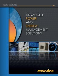
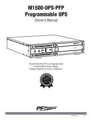
ISOLATED vs. BALANCED POWERPower Modes in the MAX® <strong>5510</strong>Single-phase grounded-neutral powerThe standard method of residential power delivery in the U.S.The neutral, or "grounded" conductor, is bonded to the earth, or"grounding" conductor. The N-G panel bond creates a severeimbalance with respect to common-mode currents, which canlead to "hum" in A/V equipment. There are three problems withthis configuration that are specifically targeted by our "Isolated"and "Balanced" power modes:1. Line and neutral current imbalance. Unbalanced currents inthe L-N can radiate magnetic fields, which can couple inductivelyfrom connected power cords to nearby A/V cables.2. Ground skew. Voltage drops due to common-mode currentflowing into the earth ground can cause a skew between signalground references in interconnected A/V equipment.3. Line and neutral voltage imbalance. Unbalanced voltagesfrom line and neutral to ground can cause connected powercords to radiate electrical fields, which can couple capacitively tonearby A/V cables.Isolated PowerSupplyLINENEUTRALGROUNDEquipmentLINENEUTRALGROUNDWith "Isolated Power" the N-G panel bond is broken by floatingthe line and neutral, and the ground reference voltage is driven toneutralize the hum-producing ground leakage currents (2).Consequently, L-N currents are equalized, effectively eliminatingmagnetic field radiation from connected power cords throughcurrent phase cancellation (1). Radiated electrical fields can stillbe evident (but to a much lesser degree than with grounded-neutralpower), unless the impedances from L-G and N-G in theconnected equipment are equal.Balanced PowerSupplyLINENEUTRALGROUNDEquipmentLINENEUTRALGROUNDWith "Balanced Power", the asymmetric, zero-volt N-G referenceat the panel is replaced by a symmetric ground referencebetween line and neutral. Hum-producing common-modecurrents (2) and radiated electrostatic fields in the connectedpower cords (3) are both eliminated by voltage phase cancellation.Radiated magnetic fields can still be evident (but to a muchlesser degree than with grounded-neutral power), unless theimpedances from L-G and N-G in the connected equipment areequal.Conclusion"Balanced" and "Isolated" Power are both exceedingly efficientat overcoming the inherent problems of the unbalanced earthground reference in domestic single-phase power systems,with small but definable distinctions. They are both effective inreducing common mode currents and radiated magnetic andelectrostatic fields from connected power cords. The primarydifference is simple: "Isolated Power" is better at reducing themagnetic (inductive) component, and "Balanced Power" is betterat reducing the electrical (capacitive) component. Because allA/V cables have some amount of inductance and capacitance(defined collectively as "impedance"), they are susceptible toboth types of interference, and the trade-offs will vary withthe system configurations.USA & Canada (800) 472-5555 • (707) 283-5900 • Fax (707) 283-5901 11
TROUBLESHOOTINGMy power cable does not reach the walloutlet. Can I use any extension cord tomake it reach?No, <strong>Panamax</strong> extension cords are the onlyextension cords that you can use while keepingyour warranty valid.The provided coax or telephone jumpercables are not long enough to reach myequipment. Can I use other cables?Yes, any length cable of the same type is fine.There is an audible buzz/hum comingfrom my Max <strong>5510</strong>-Pro. What is thecause of this and how do I make it goaway?This can be caused by certain appliances; mostcommonly lamps with High-Low dimmer switchesand some room heaters, which use only halfof the AC sine wave. These appliances distortthe AC wave through a small DC bias placed onthe AC supply. Some custom audio equipmentespeciallyamplifiers with toroidal power transformers,may react unfavorably to this distortion,and buzz. The Max <strong>5510</strong>-Pro’s isolation transformerwill remove this waveform distortion andprotect the loads plugged into the transformerisolatedoutlets. If the distortion is bad, you mayactually hear the Max <strong>5510</strong>-Pro buzzing slightlyas it works to correct the AC power. The bestway to stop the buzz is to find the source of thedisturbance (most likely a quartz lamp) and plugit into a different branch circuit. <strong>Panamax</strong>Technical Support will be glad to help you if youhave any questions about this.The 6 Amp, Isolation Transformer circuitbreaker continually trips. What is theproblem?The four Isolation Transformer outlets share the720 VA Isolation transformer for their powersource. The connected equipment plugged intothe four outlets are drawing more than 6 Ampscollectively, causing the circuit breaker to trip.These four outlets are designed specifically forlow-current, digital source components. Checkto see if you have connected a high currentamplifier or subwoofer to the IsolationTransformer Outlets. If so, unplug the high currentcomponents and plug them into the HighCurrent Outlet Bank.The Isolation Transformer Outlets are notswitching ON or OFF with the MAX <strong>5510</strong>-Pro. How can I fix this?These outlets may be set as either switched oralways-on outlets. The 2-position, SwitchedOutlets Delay switch on the back panel controlsthis. Change the setting of this switch fromalways-on to a 10 second delay. This will allowthe Isolation Transformer Outlets to becomeswitched outlets.The MAX <strong>5510</strong>-Pro is ON but theVoltmeter and Ammeter are not lit up.What is the problem?Check the Meter Light Dimmer control to see ifthe lighting is turned OFF. The pushbuttonswitch cycles between High-Amber, Low-Amber,High-Blue, Low-Blue and OFF. Call <strong>Panamax</strong>Customer Service for help if the switch has noaffect.I connected the LED Convenience Lampand the lamp will not work. What is theproblem?Check to see if the MAX <strong>5510</strong>-Pro is in anunsafe voltage condition by looking to see if theunsafe voltage LED is lit. If the LED is lit, thenwait until voltage is back to normal and the lightwill turn back on. If the unsafe voltage LED isOFF and the light is still not on, call <strong>Panamax</strong>Customer Service for help.12USA & Canada (800) 472-5555 • (707) 283-5900 • Fax (707) 283-5901
PANAMAX, the <strong>Panamax</strong> logo and MAX are registered US trademarks of <strong>Panamax</strong>. <strong>ACRegenerator</strong> and SignalPerfect are trademarks of PANAMAX.SIDACtor is a registered US trademark of Teccor Electronics, Inc. TiVo is a trademark of TiVo, Inc.USA & Canada (800) 472-5555 • (707) 283-5900 • Fax (707) 283-5901
1690 Corporate Circle, Petaluma, CA 94954Tel: (707) 283-5900Fax:: (707) 283-5901Email: sales@panamax.comWeb: www.panamax.com© 2004 <strong>Panamax</strong> INS0762 Rev A 12/04