Mathcad - P00666.xmcd - CBU
Mathcad - P00666.xmcd - CBU
Mathcad - P00666.xmcd - CBU
- No tags were found...

Create successful ePaper yourself
Turn your PDF publications into a flip-book with our unique Google optimized e-Paper software.
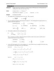
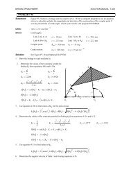
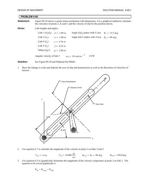
DESIGN OF MACHINERY SOLUTION MANUAL 6-66-1PROBLEM 6-66Statement:Given:Figure P6-28 shows a quick-return mechanism with dimensions. Use a graphical method to calculatethe velocities of points A, B, and C and the velocity of slip for the position shown.Link lengths and angles:Link 1 (O 2 O 4 ) d 1.69inAngle O 2 O 4 makes with X axis 15.5degLink 2 (L 2 ) a 1.00inAngle link 2 makes with X axis 99degLink 4 (L 4 ) e 4.76inLink 5 (L 5 ) f 4.55inOffset (O 2 C) g 2.86inAngular velocity of link 2 10radsec 1CCWSolution: See Figure P6-28 and <strong>Mathcad</strong> file P0666.1. Draw the linkage to scale and indicate the axes of slip and transmission as well as the directions of velocities ofinterest.Axis of transmissionBDirection of VA34YAxis of slipA2.0683244.228°O 4O 2X2. Use equation 6.7 to calculate the magnitude of the velocity at point A on links 2 and 3.V A2 a V A2 10.000 in VA2 90deg VA2 189.0degsec3. Use equation 6.5 to (graphically) determine the magnitude of the velocity components at point A on link 3. Theequation to be solved graphically isV A3 = V trans + V slip
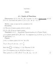
DESIGN OF MACHINERY SOLUTION MANUAL 6-66-2a. Choose a convenient velocity scale and layout the known vector V A3 .b. From the tip of V A3 , draw a construction line with the direction of V slip , magnitude unknown.c. From the tail of V A3 , draw a construction line with the direction of V trans , magnitude unknown.d. Complete the vector triangle by drawing V slip from the tip of V trans to the tip of V A3 and drawing V trans fromthe tail of V A3 to the intersection of the V slip construction line.Y0 5 in/secVA3XV trans1.154V slip1.6344. From the velocity triangle we have:5insec 1Velocity scale factor: k v inV slipV trans 1.634ink v V slip 8.170 insec 1.154ink v V trans 5.770 insec5. The true velocity of point A on link 4 is V trans ,V A4 V transV A4 5.77 insec6. Determine the angular velocity of link 4 using equation 6.7.From the linkage layout above: c 2.068inand 44.228deg V A4 2.790 radcsecCCW7. Determine the magnitude and sense of the vector V B using equation 6.7.V B e V B 13.281 insec VB 90deg VB 134.228 deg8. Draw links 1, 4, 5, and 6 to a convenient scale. Indicate the directions of the velocity vectors of interest. (Seenext page.)
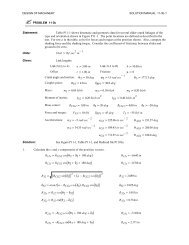
DESIGN OF MACHINERY SOLUTION MANUAL 6-66-3Direction of VCBDirection of VBBC655.805°4Direction of VCYA3244.228°O 2XO49. Use equation 6.5 to (graphically) determine the magnitude of the velocity at point C. The equation to be solvedgraphically isV C = V B + V CBa. Choose a convenient velocity scale and layout the known vector V B .b. From the tip of V B , draw a construction line with the direction of V CB , magnitude unknown.c. From the tail of V B , draw a construction line with the direction of V C , magnitude unknown.d. Complete the vector triangle by drawing V CB from the tip of V B to the intersection of the V C constructionline and drawing V C from the tail of V B to the intersection of the V CB construction line.10. From the velocity triangle we have:5insec 1Velocity scale factor: k v inV C 1.659ink v V C 8.30 insecV B0Y5 in/sec VC 180degVCBVCX1.659