Product Name Vector VS131 GPS Compass - NavtechGPS
Product Name Vector VS131 GPS Compass - NavtechGPS
Product Name Vector VS131 GPS Compass - NavtechGPS

Create successful ePaper yourself
Turn your PDF publications into a flip-book with our unique Google optimized e-Paper software.
<strong>Vector</strong> <strong>Product</strong> <strong>VS131</strong> <strong>GPS</strong> <strong>Name</strong> <strong>Compass</strong>Quick User Reference Guide GuidePart No. 875-0311-000 Part No. Rev. B1www.hemispheregps.com
This device complies with part 15 of the FCC Rules. Operation is subject to the following twoconditions:(1) This device may not cause harmful interference, and(2) this device must accept any interference received, including interference that may causeundesired operation.Copyright NoticeCopyright Hemisphere GNSS, Inc. (2013). All rights reserved.No part of this manual may be reproduced, transmitted, transcribed, stored in a retrieval system ortranslated into any language or computer language, in any form or by any means, electronic,mechanical, magnetic, optical, chemical, manual or otherwise, without the prior writtenpermission of Hemisphere GNSS.TrademarksHemisphere <strong>GPS</strong> ® , the Hemisphere <strong>GPS</strong> logo, COAST TM , Crescent ® , Earthworks ® , Eclipse TM , e-Dif ® ,L-Dif TM , miniEclipse TM , PocketMAX PC TM , PocketMAX TM , PocketMax3 TM , S320 TM , SBX-4 TM ,SureTrack ® , <strong>Vector</strong> TM , XF1 TM , and XF2 TM are proprietary trademarks of Hemisphere GNSS, Inc.Other trademarks are the properties of their respective owners.PatentsHemisphere GNSS products may be covered by one or more of the following patents:U.S. PatentsAustralia Patents6111549 6876920 7400956 8000381 8214111 20022445396397147 7142956 7429952 8018376 8217833 20023256456469663 7162348 7437230 8085196 8265826 20043204016501346 7277792 7460942 8102325 82711946539303 7292185 7689354 8138970 83075356549091 7292186 7808428 8140223 83116966711501 7373231 7835832 8174437 83348046744404 7388539 7885745 8184050 RE413586865465 7400294 7948769 8190337Other U.S. and foreign patents pending.Notice to CustomersContact your local dealer for technical assistance. To find the authorized dealer near you:Hemisphere GNSS, Inc.8444 N 90th St, Suite 120Scottsdale, AZ 85258 USAPhone: (480) 348-9919Fax: (480) 348-6370precision@hemispheregps.comwww.hemispheregps.comTechnical SupportIf you need to contact Hemisphere GNSS Technical Support:Hemisphere GNSS, Inc.8444 N 90th St, Suite 120Scottsdale, AZ 85258 USAPhone: (480) 348-9919Fax: (480) 348-6370techsupport@hemispheregps.comDocumentation FeedbackHemisphere GNSS is committed to the quality and continuous improvement of our products andservices. We urge you to provide Hemisphere GNSS with any feedback regarding this guide bywriting to the following email address: techsupport@hemispheregps.com.
Warranty NoticeCOVERED PRODUCTS: This warranty covers all products manufactured by Hemisphere <strong>GPS</strong> and purchased by the endpurchaser (the "<strong>Product</strong>s"), unless otherwise specifically and expressly agreed in writing by Hemisphere <strong>GPS</strong>.LIMITED WARRANTY: Hemisphere <strong>GPS</strong> warrants solely to the end purchaser of the <strong>Product</strong>s, subject to the exclusionsand procedures set forth below, that the <strong>Product</strong>s sold to such end purchaser and its internal components shall be free,under normal use and maintenance, from defects in materials, and workmanship and will substantially conform toHemisphere <strong>GPS</strong>’s applicable specifications for the <strong>Product</strong>, for a period of 12 months from delivery of such <strong>Product</strong> tosuch end purchaser (the ”Warranty Period”). Repairs and replacement components for the <strong>Product</strong>s are warranted, subjectto the exclusions and procedures set forth below, to be free, under normal use and maintenance, from defects in materialand workmanship, and will substantially conform to Hemisphere <strong>GPS</strong>’s applicable specifications for the <strong>Product</strong>, for 90days from performance or delivery, or for the balance of the original Warranty Period, whichever is greater.EXCLUSION OF ALL OTHER WARRANTIES. The LIMITED WARRANTY shall apply only if the <strong>Product</strong> is properly andcorrectly installed, configured, interfaced, maintained, stored, and operated in accordance with Hemisphere <strong>GPS</strong>’s relevantUser’s Manual and Specifications, AND the <strong>Product</strong> is not modified or misused. The <strong>Product</strong> is provided “AS IS” and theimplied warranties of MERCHANTABILITY and FITNESS FOR A PARTICULAR PURPOSE and ALL OTHER WARRANTIES,express, implied or arising by statute, by course of dealing or by trade usage, in connection with the design, sale,installation, service or use of any products or any component thereof, are EXCLUDED from this transaction and shall notapply to the <strong>Product</strong>. The LIMITED WARRANTY is IN LIEU OF any other warranty, express or implied, including but notlimited to, any warranty of MERCHANTABILITY or FITNESS FOR A PARTICULAR PURPOSE, title, and non-infringement.LIMITATION OF REMEDIES. The purchaser’s EXCLUSIVE REMEDY against Hemisphere <strong>GPS</strong> shall be, at Hemisphere<strong>GPS</strong>’s option, the repair or replacement of any defective <strong>Product</strong> or components thereof. The purchaser shall notifyHemisphere <strong>GPS</strong> or a Hemisphere <strong>GPS</strong>’s approved service center immediately of any defect. Repairs shall be madethrough a Hemisphere <strong>GPS</strong> approved service center only. Repair, modification or service of Hemisphere <strong>GPS</strong> products byany party other than a Hemisphere <strong>GPS</strong> approved service center shall render this warranty null and void. The remedy inthis paragraph shall only be applied in the event that the <strong>Product</strong> is properly and correctly installed, configured, interfaced,maintained, stored, and operated in accordance with Hemisphere <strong>GPS</strong>’s relevant User’s Manual and Specifications, ANDthe <strong>Product</strong> is not modified or misused. NO OTHER REMEDY (INCLUDING, BUT NOT LIMITED TO, SPECIAL, INDIRECT,INCIDENTAL, CONSEQUENTIAL OR CONTINGENT DAMAGES FOR LOST PROFITS, LOST SALES, INJURY TO PERSON ORPROPERTY, OR ANY OTHER INCIDENTAL OR CONSEQUENTIAL LOSS) SHALL BE AVAILABLE TO PURCHASER, even ifHemisphere <strong>GPS</strong> has been advised of the possibility of such damages. Without limiting the foregoing, Hemisphere <strong>GPS</strong>shall not be liable for any damages of any kind resulting from installation, use, quality, performance or accuracy of any<strong>Product</strong>.HEMISPHERE IS NOT RESPONSIBLE FOR PURCHASER’S NEGLIGENCE OR UNAUTHORIZED USES OF THEPRODUCT. IN NO EVENT SHALL HEMISPHERE <strong>GPS</strong> BE IN ANY WAY RESPONSIBLE FOR ANY DAMAGES RESULTINGFROM PURCHASER’S OWN NEGLIGENCE, OR FROM OPERATION OF THE PRODUCT IN ANY WAY OTHER THAN ASSPECIFIED IN HEMISPHERE <strong>GPS</strong>’S RELEVANT USER’S MANUAL AND SPECIFICATIONS. Hemisphere <strong>GPS</strong> is NOTRESPONSIBLE for defects or performance problems resulting from (1) misuse, abuse, improper installation, neglect of<strong>Product</strong>; (2) the utilization of the <strong>Product</strong> with hardware or software products, information, data, systems, interfaces ordevices not made, supplied or specified by Hemisphere <strong>GPS</strong>; (3) the operation of the <strong>Product</strong> under any specification otherthan, or in addition to, the specifications set forth in Hemisphere <strong>GPS</strong>’s relevant User’s Manual and Specifications; (4)damage caused by accident or natural events, such as lightning (or other electrical discharge) or fresh/salt waterimmersion of <strong>Product</strong>; (5) damage occurring in transit; (6) normal wear and tear; or (7) the operation or failure of operationof any satellite-based positioning system or differential correction service; or the availability or performance of anysatellite-based positioning signal or differential correction signal.THE PURCHASER IS RESPONSIBLE FOR OPERATING THE VEHICLE SAFELY. The purchaser is solely responsiblefor the safe operation of the vehicle used in connection with the <strong>Product</strong>, and for maintaining proper system controlsettings. UNSAFE DRIVING OR SYSTEM CONTROL SETTINGS CAN RESULT IN PROPERTY DAMAGE, INJURY, OR DEATH.The purchaser is solely responsible for his/her safety and for the safety of others. The purchaser is solely responsible formaintaining control of the automated steering system at all times. THE PURCHASER IS SOLELY RESPONSIBLE FORENSURING THE PRODUCT IS PROPERLY AND CORRECTLY INSTALLED, CONFIGURED, INTERFACED, MAINTAINED,STORED, AND OPERATED IN ACCORDANCE WITH HEMISPHERE <strong>GPS</strong>’S RELEVANT USER’S MANUAL ANDSPECIFICATIONS. Hemisphere <strong>GPS</strong> does not warrant or guarantee the positioning and navigation precision or accuracyobtained when using <strong>Product</strong>s. <strong>Product</strong>s are not intended for primary navigation or for use in safety of life applications.The potential accuracy of <strong>Product</strong>s as stated in Hemisphere <strong>GPS</strong> literature and/or <strong>Product</strong> specifications serves to provideonly an estimate of achievable accuracy based on performance specifications provided by the satellite service operator (i.e.US Department of Defense in the case of <strong>GPS</strong>) and differential correction service provider. Hemisphere <strong>GPS</strong> reserves theright to modify <strong>Product</strong>s without any obligation to notify, supply or install any improvements or alterations to existing<strong>Product</strong>s.GOVERNING LAW. This agreement and any disputes relating to, concerning or based upon the <strong>Product</strong> shall begoverned by and interpreted in accordance with the laws of the State of Arizona.OBTAINING WARRANTY SERVICE. In order to obtain warranty service, the end purchaser must bring the <strong>Product</strong> to aHemisphere <strong>GPS</strong> approved service center along with the end purchaser's proof of purchase. Hemisphere <strong>GPS</strong> does notwarrant claims asserted after the end of the warranty period. For any questions regarding warranty service or to obtaininformation regarding the location of any of Hemisphere <strong>GPS</strong> approved service center, contact Hemisphere <strong>GPS</strong> at thefollowing address:Hemisphere <strong>GPS</strong>8444 N. 90th Street, Suite 130Scottsdale, AZ 85258Phone: 480-348-9919 Fax: 480-348-6370techsupport@hemispheregps.comwww.hemispheregps.com
ContentsChapter 1 Introduction . . . . . . . . . . . . . . . . . . . . . . . . . . . . . . 1What’s In This Guide? . . . . . . . . . . . . . . . . . . . . . . . . . . . . . . . . . . . . 2<strong>Product</strong> Overview . . . . . . . . . . . . . . . . . . . . . . . . . . . . . . . . . . . . . . . . 2Key Features . . . . . . . . . . . . . . . . . . . . . . . . . . . . . . . . . . . . . . . . . . . . 3What’s Included in Your Kit . . . . . . . . . . . . . . . . . . . . . . . . . . . . . . . . 3Using <strong>Vector</strong>PC to Communicate with the <strong>VS131</strong> . . . . . . . . . . . . . . 4Chapter 2 Understanding the <strong>VS131</strong> . . . . . . . . . . . . . . . . . . . 5<strong>GPS</strong> Overview . . . . . . . . . . . . . . . . . . . . . . . . . . . . . . . . . . . . . . . . . . 6<strong>GPS</strong> Operation . . . . . . . . . . . . . . . . . . . . . . . . . . . . . . . . . . . . . . 6Differential Operation . . . . . . . . . . . . . . . . . . . . . . . . . . . . . . . . 6<strong>VS131</strong> Overview . . . . . . . . . . . . . . . . . . . . . . . . . . . . . . . . . . . . . . . . . 8Fixed Baseline Moving Base Station RTK . . . . . . . . . . . . . . . . 8Supplemental Sensors . . . . . . . . . . . . . . . . . . . . . . . . . . . . . . . 9Time Constants . . . . . . . . . . . . . . . . . . . . . . . . . . . . . . . . . . . . 10Chapter 3 Installing the <strong>VS131</strong> . . . . . . . . . . . . . . . . . . . . . . . 13Mounting the Antennas . . . . . . . . . . . . . . . . . . . . . . . . . . . . . . . . . . 14Antenna Options . . . . . . . . . . . . . . . . . . . . . . . . . . . . . . . . . . . 14Mounting Orientation . . . . . . . . . . . . . . . . . . . . . . . . . . . . . . . 14Planning the Optimal Antenna Placement . . . . . . . . . . . . . . . 15Mounting Options . . . . . . . . . . . . . . . . . . . . . . . . . . . . . . . . . . 16Routing and Securing the Antenna Cable . . . . . . . . . . . . . . . 19Mounting the Receiver . . . . . . . . . . . . . . . . . . . . . . . . . . . . . . . . . . 20Routing and Connecting the Cables . . . . . . . . . . . . . . . . . . . . . . . . 21Connecting the Receiver to External Devices . . . . . . . . . . . . . . . . 22Default Parameters . . . . . . . . . . . . . . . . . . . . . . . . . . . . . . . . . . . . . 23Chapter 4 Operating the <strong>VS131</strong> . . . . . . . . . . . . . . . . . . . . . . 25Powering the Receiver On/Off . . . . . . . . . . . . . . . . . . . . . . . . . . . . . 26LED Indicators . . . . . . . . . . . . . . . . . . . . . . . . . . . . . . . . . . . . . . . . . 27Startup . . . . . . . . . . . . . . . . . . . . . . . . . . . . . . . . . . . . . . . . . . . . . . . 28Using the Menus . . . . . . . . . . . . . . . . . . . . . . . . . . . . . . . . . . . . . . . 29Configuring the <strong>VS131</strong> . . . . . . . . . . . . . . . . . . . . . . . . . . . . . . . . . . . 30Config Wizard Menu . . . . . . . . . . . . . . . . . . . . . . . . . . . . . . . . 30Using the Config Wizard . . . . . . . . . . . . . . . . . . . . . . . . . . . . . 31Disabling the Aiding Features . . . . . . . . . . . . . . . . . . . . . . . . . . . . . 33Disabling Tilt Aiding . . . . . . . . . . . . . . . . . . . . . . . . . . . . . . . . 33Disabling Gyro Aiding . . . . . . . . . . . . . . . . . . . . . . . . . . . . . . . 33Adjusting the Time Constants . . . . . . . . . . . . . . . . . . . . . . . . . . . . . 34<strong>Vector</strong> <strong>VS131</strong> <strong>GPS</strong> <strong>Compass</strong> User Guide iii PN 875-0311-000 Rev B1
ContentsConnecting to Existing Navigation Systems . . . . . . . . . . . . . . . . . 35Viewing <strong>GPS</strong>/D<strong>GPS</strong> Status . . . . . . . . . . . . . . . . . . . . . . . . . . . . . . . 35Do I Have a Signal? . . . . . . . . . . . . . . . . . . . . . . . . . . . . . . . . . 35How Good is the Quality of My Signal? . . . . . . . . . . . . . . . . . 35Appendix A Troubleshooting . . . . . . . . . . . . . . . . . . . . . . . . . . 37Appendix B FAQ . . . . . . . . . . . . . . . . . . . . . . . . . . . . . . . . . . . . 41Appendix C Menu Map . . . . . . . . . . . . . . . . . . . . . . . . . . . . . . . 45<strong>Vector</strong> Menu . . . . . . . . . . . . . . . . . . . . . . . . . . . . . . . . . . . . . . . . . . . 46<strong>GPS</strong> Menu . . . . . . . . . . . . . . . . . . . . . . . . . . . . . . . . . . . . . . . . . . . . . 47Differential Menu . . . . . . . . . . . . . . . . . . . . . . . . . . . . . . . . . . . . . . . 48Config Wizard Menu . . . . . . . . . . . . . . . . . . . . . . . . . . . . . . . . . . . . 50System Setup Menu . . . . . . . . . . . . . . . . . . . . . . . . . . . . . . . . . . . . 51Appendix D Technical Specifications . . . . . . . . . . . . . . . . . . . 53<strong>VS131</strong> Receiver Specifications . . . . . . . . . . . . . . . . . . . . . . . . . . . . 54A21 Antenna Specifications . . . . . . . . . . . . . . . . . . . . . . . . . . . . . . 57A31 Antenna Specifications . . . . . . . . . . . . . . . . . . . . . . . . . . . . . . 58Index . . . . . . . . . . . . . . . . . . . . . . . . . . . . . . . . . . . . . . . . . . . . . . . 61End User License Agreement . . . . . . . . . . . . . . . . . . . . . . . . . . . . 63Warranty Notice . . . . . . . . . . . . . . . . . . . . . . . . . . . . . . . . . . . . . . 6621. TERMINATION. Licensee may terminate this Agreement at any time without cause. Hemisphere may terminate thisAgreement on 30 days notice to Licensee if Licensee fails to materially comply with each provision of thisAgreement unless such default is cured within the 30 days. Any such termination by a party shall be in addition toand without prejudice to such rights and remedies as may be available, including injunction and other equitableremedies. Upon receipt by Licensee of written notice of termination from Hemisphere or termination by Licensee,Licensee shall at the end of any notice period (a) cease using the Software; and (b) return to Hemisphere (or destroyand provide a certificate of a Senior Officer attesting to such destruction) the Software and all related material andany magnetic or optical media provided to Licensee. The provisions of Sections 6), 7), 8), 9), 10), 15), 21), 26) and 27)herein shall survive the expiration or termination of this Agreement for any reason.22. EXPORT RESTRICTIONS. Licensee agrees that Licensee will comply with all export control legislation of Canada,the United States, Australia and any other applicable country's laws and regulations, whether under the ArmsExport Control Act, the International Traffic in Arms Regulations, the Export Administration Regulations, theregulations of the United States Departments of Commerce, State, and Treasury, or otherwise as well as the exportcontrol legislation of all other countries.23. PRODUCT COMPONENTS. The <strong>Product</strong> may contain third party components. Those third party components maybe subject to additional terms and conditions. Licensee is required to agree to those terms and conditions in order touse the <strong>Product</strong>.24. FORCE MAJEURE EVENT. Neither party will have the right to claim damages as a result of the other's inability toperform or any delay in performance due to unforeseeable circumstances beyond its reasonable control, such aslabor disputes, strikes, lockouts, war, riot, insurrection, epidemic, Internet virus attack, Internet failure, supplierfailure, act of God, or governmental action not the fault of the non-performing party.25. FORUM FOR DISPUTES. The parties agree that the courts located in the State of Arizona and the courts of appealthere from will have exclusive jurisdiction to resolve any disputes between Licensee and Hemisphere concerningthis Agreement or Licensee's use or inability to use the Software and the parties hereby irrevocably agree to attornto the jurisdiction of those courts. Notwithstanding the foregoing, either party may apply to any court of competentjurisdiction for injunctive relief.26. APPLICABLE LAW. This Agreement shall be governed by the laws of the State of Arizona, exclusive of any of itschoice of law and conflicts of law jurisprudence.27. CISG. The United Nations Convention on Contracts for the International Sale of Goods will not apply to thisAgreement or any transaction hereunder.28. GENERAL. This is the entire agreement between Licensee and Hemisphere relating to the <strong>Product</strong> and Licensee'suse of the same, and supersedes all prior, collateral or contemporaneous oral or written representations, warrantiesor agreements regarding the same. No amendment to or modification of this Agreement will be binding unless inwriting and signed by duly authorized representatives of the parties. Any and all terms and conditions set out in anycorrespondence between the parties or set out in a purchase order which are different from or in addition to theterms and conditions set forth herein, shall have no application and no written notice of same shall be required. Inthe event that one or more of the provisions of this Agreement is found to be illegal or unenforceable, thisAgreement shall not be rendered inoperative but the remaining provisions shall continue in full force and effect.<strong>Vector</strong> <strong>VS131</strong> <strong>GPS</strong> <strong>Compass</strong> User Guide iv PN 875-0311-000 Rev B1
positioning and navigation accuracy obtainable with the Software as stated in the <strong>Product</strong> or Softwaredocumentation serves to provide only an estimate of achievable accuracy based on specifications provided by theUS Department of Defense for <strong>GPS</strong> positioning and D<strong>GPS</strong> service provider performance specifications, whereapplicable.10. WARRANTY DISCLAIMER. EXCEPT AS EXPRESSLY SET OUT IN THIS AGREEMENT, HEMISPHERE MAKES NOREPRESENTATION, WARRANTY OR CONDITION OF ANY KIND TO LICENSEE, WHETHER VERBAL OR WRITTENAND HEREBY DISCLAIMS ALL REPRESENTATIONS, WARRANTIES AND CONDITIONS OF ANY KIND INCLUDINGFITNESS FOR A PARTICULAR PURPOSE, MERCHANTABILITY, ACCURACY, RELIABILITY OR THAT THE USE OF THESOFTWARE WILL BE UNINTERRUPTED OR ERROR-FREE AND HEREBY DISCLAIMS ALL REPRESENTATIONS,WARRANTIES AND CONDITIONS ARISING AS A RESULT OF CUSTOM, USAGE OR TRADE AND THOSE ARISINGUNDER STATUTE.11. LIMITS ON WARRANTY DISCLAIMER. Some jurisdictions do not allow the exclusion of implied warranties orconditions, so some of the above exclusions may not apply to Licensee. In that case, any implied warranties orconditions which would then otherwise arise will be limited in duration to ninety (90) days from the date of thelicense of the Software or the purchase of the <strong>Product</strong>. The warranties given herein give Licensee specific legal rightsand Licensee may have other rights which may vary from jurisdiction to jurisdiction.12. CHANGE TO WARRANTY. No employee or agent of Hemisphere is authorized to change the warranty provided orthe limitation or disclaimer of warranty provisions. All such changes will only be effective if pursuant to a separateagreement signed by senior officers of the respective parties.13. WARRANTY CLAIM. In the event Licensee has a warranty claim Licensee must first check for and install allUpdates that are made available. The warranty will not otherwise be honored. Proof of purchase may be required.Hemisphere does not honor claims asserted after the end of the Warranty Period.14. LICENSEE REMEDIES. In all cases which involve a failure of the Software to conform in any material respect to thedocumentation during the Warranty Period or a breach of a warranty, Hemisphere's sole obligation and liability, andLicensee's sole and exclusive remedy, is for Hemisphere, at Hemisphere's option, to (a) repair the Software, (b)replace the Software with software conforming to the documentation, or (c) if Hemisphere is unable, on areasonable commercial basis, to repair the Software or to replace the Software with conforming software withinninety (90) days, to terminate this Agreement and thereafter Licensee shall cease using the Software. Hemispherewill also issue a refund for the price paid by Licensee less an amount on account of amortization, calculated on astraight-line basis over a deemed useful life of three (3) years.15. LIMITATION OF LIABILITY. IN NO EVENT WILL HEMISPHERE BE LIABLE TO LICENSEE FOR ANY INCIDENTAL,CONSEQUENTIAL, SPECIAL OR INDIRECT DAMAGES INCLUDING ARISING IN RELATION TO ANY LOSS OF DATA,INCOME, REVENUE, GOODWILL OR ANTICIPATED SAVINGS EVEN IF HEMISPHERE HAS BEEN INFORMED OF THEPOSSIBILITY OF SUCH LOSS OR DAMAGE. FURTHER, IN NO EVENT WILL HEMISPHERE'S TOTAL CUMULATIVELIABILITY HEREUNDER, FROM ALL CAUSES OF ACTION OF ANY KIND, EXCEED THE TOTAL AMOUNT PAID BYLICENSEE TO HEMISPHERE TO PURCHASE THE PRODUCT. THIS LIMITATION AND EXCLUSION APPLIESIRRESPECTIVE OF THE CAUSE OF ACTION, INCLUDING BUT NOT LIMITED TO BREACH OF CONTRACT,NEGLIGENCE, STRICT LIABILITY, TORT, BREACH OF WARRANTY, MISREPRESENTATION OR ANY OTHER LEGALTHEORY AND WILL SURVIVE A FUNDAMENTAL BREACH.16. LIMITS ON LIMITATION OF LIABILITY. Some jurisdictions do not allow for the limitation or exclusion of liability forincidental or consequential damages, so the above limitation or exclusion may not apply to Licensee and Licenseemay also have other legal rights which may vary from jurisdiction to jurisdiction.17. BASIS OF BARGAIN. Licensee agrees and acknowledges that Hemisphere has set its prices and the parties haveentered into this Agreement in reliance on the limited warranties, warranty disclaimers and limitations of liability setforth herein, that the same reflect an agreed-to allocation of risk between the parties (including the risk that aremedy may fail of its essential purpose and cause consequential loss), and that the same forms an essential basisof the bargain between the parties. Licensee agrees and acknowledges that Hemisphere would not have been ableto sell the <strong>Product</strong> at the amount charged on an economic basis without such limitations.18. PROPRIETARY RIGHTS INDEMNITY. Hemisphere shall indemnify, defend and hold harmless Licensee from andagainst any and all actions, claims, demands, proceedings, liabilities, direct damages, judgments, settlements, fines,penalties, costs and expenses, including royalties and attorneys' fees and related costs, in connection with or arisingout of any actual infringement of any third party patent, copyright or other intellectual property right by the Softwareor by its use, in accordance with this Agreement and documentation, PROVIDED THAT: (a) Hemisphere has the rightto assume full control over any action, claim, demand or proceeding, (b) Licensee shall promptly notify Hemisphereof any such action, claim, demand, or proceeding, and (c) Licensee shall give Hemisphere such reasonableassistance and tangible material as is reasonably available to Licensee for the defense of the action, claim, demandor proceeding. Licensee shall not settle or compromise any of same for which Hemisphere has agreed to assumeresponsibility without Hemisphere's prior written consent. Licensee may, at its sole cost and expense, retainseparate counsel from the counsel utilized or retained by Hemisphere.19. INFRINGEMENT. If use of the Software may be enjoined due to a claim of infringement by a third party then, at itssole discretion and expense, Hemisphere may do one of the following: (a) negotiate a license or other agreement sothat the <strong>Product</strong> is no longer subject to such a potential claim, (b) modify the <strong>Product</strong> so that it becomes noninfringing,provided such modification can be accomplished without materially affecting the performance andfunctionality of the <strong>Product</strong>, (c) replace the Software, or the <strong>Product</strong>, with non-infringing software, or product, ofequal or better performance and quality, or (d) if none of the foregoing can be done on a commercially reasonablebasis, terminate this license and Licensee shall stop using the <strong>Product</strong> and Hemisphere shall refund the price paid byLicensee less an amount on account of amortization, calculated on a straight-line basis over a deemed useful life ofthree (3) years.The foregoing sets out the entire liability of Hemisphere and the sole obligations of Hemisphere to Licensee inrespect of any claim that the Software or its use infringes any third party rights.Chapter 1: IntroductionWhat’s In This Guide?<strong>Product</strong> OverviewWhat’s Included in Your KitUsing <strong>Vector</strong>PC to Communicate with the <strong>VS131</strong>20. INDEMNIFICATION. Except in relation to an infringement action, Licensee shall indemnify and hold Hemisphereharmless from any and all claims, damages, losses, liabilities, costs and expenses (including reasonable fees oflawyers and other professionals) arising out of or in connection with Licensee's use of the <strong>Product</strong>, whether direct orindirect, including without limiting the foregoing, loss of data, loss of profit or business interruption.<strong>Vector</strong> <strong>VS131</strong> <strong>GPS</strong> <strong>Compass</strong> User Guide 1 PN 875-0311-000 Rev B1
Chapter 1: IntroductionWhat’s In This Guide?This User Guide provides the following information to get you up and running quicklywith your <strong>Vector</strong> <strong>VS131</strong> <strong>GPS</strong> compass.• This chapter briefly describes the <strong>VS131</strong> and the parts in your <strong>VS131</strong> kit.• Chapter 2, “Understanding the <strong>VS131</strong>” discusses <strong>GPS</strong> and differentialoperation as well as sensors and time constants related to the <strong>VS131</strong>.• Chapter 3, “Installing the <strong>VS131</strong>” describes how to mount the antennas andreceiver, connect the cables, and power the system.• Chapter 4, “Operating the <strong>VS131</strong>” provides instructions on configuring thereceiver, disabling aiding features, adjusting the time constants, andoperating the receiver.• Appendix A, “Troubleshooting” provides possible solutions for issues.• Appendix B, “FAQ” includes answer to common questions.• Appendix C, “Menu Map” provides a full map of all system menus.• Appendix D, “Technical Specifications” lists the technical specifications ofthe <strong>VS131</strong> and the included antennas.Note: Throughout the rest of this user guide the <strong>Vector</strong> <strong>VS131</strong> <strong>GPS</strong> <strong>Compass</strong> isreferred to simply as the <strong>VS131</strong>.<strong>Product</strong> OverviewThe <strong>VS131</strong> provides a highly-accurate <strong>GPS</strong>heading that takes into account the pitch, roll, andspeed of various vehicles and vessels and is idealfor professional machine control and navigationapplications in areas where either beacon or L-band positioning can be achieved. Featuring aHemisphere <strong>GPS</strong> Crescent ® <strong>Vector</strong>-based receiverand two separate antennas, <strong>VS131</strong> achievesheading accuracy ranging from 0.03º to 0.33º rms(depending on the antenna separation) and offersrobust positioning performance.With more accurate code phase measurements,improved multipath mitigation and fewercomponents than competing products, <strong>VS131</strong> offers superior accuracy and stability.The <strong>VS131</strong> receiver, with its display and user interface, can be conveniently installednear the operator, while the two antennas are mounted separately with a userdeterminedseparation (up to 5 m) to meet the desired accuracy.<strong>VS131</strong> uses L-band, SBAS (WAAS, EGNOS, MSAS, etc.), or beacon for differential <strong>GPS</strong>positioning—offering differential positioning performance of less than 0.6 m 95% ofthe time.<strong>VS131</strong> also features Hemisphere <strong>GPS</strong>’ exclusive COAST technology that enablesHemisphere <strong>GPS</strong> receivers to utilize aging differential <strong>GPS</strong> correction data for 40minutes or more without significantly affecting positioning quality. <strong>VS131</strong> is less likelyto be affected by differential signal outages due to signal blockages, weak signals, orinterference when using COAST.End User License AgreementIMPORTANT - This is an agreement (the "Agreement") between you, the end purchaser ("Licensee") and HemisphereGNSS Inc. ("Hemisphere") which permits Licensee to use the Hemisphere software (the "Software") that accompaniesthis Agreement. This Software may be licensed on a standalone basis or may be embedded in a <strong>Product</strong>. Please read andensure that you understand this Agreement before installing or using the Software Update or using a <strong>Product</strong>.In this agreement any product that has Software embedded in it at the time of sale to the Licensee shall be referred to as a"<strong>Product</strong>". As well, in this Agreement, the use of a <strong>Product</strong> shall be deemed to be use of the Software which is embeddedin the <strong>Product</strong>.BY INSTALLING OR USING THE SOFTWARE UPDATE OR THE PRODUCT, LICENSEE THEREBY AGREES TO BE LEGALLYBOUND BY THE TERMS OF THIS AGREEMENT. IF YOU DO NOT AGREE TO THESE TERMS, (I) DO NOT INSTALL OR USETHE SOFTWARE, AND (II) IF YOU ARE INSTALLING AN UPDATE TO THE SOFTWARE, DO NOT INSTALL THE UPDATE ANDPROMPTLY DESTROY IT.HEMISPHERE PROVIDES LIMITED WARRANTIES IN RELATION TO THE SOFTWARE. AS WELL, THOSE WHO USE THEEMBEDDED SOFTWARE DO SO AT THEIR OWN RISK. YOU SHOULD UNDERSTAND THE IMPORTANCE OF THESE ANDOTHER LIMITATIONS SET OUT IN THIS AGREEMENT BEFORE INSTALLING OR USING THE SOFTWARE OR THE PRODUCT.1. LICENSE. Hemisphere hereby grants to Licensee a non-transferable and non-exclusive license to use the Softwareas embedded in a <strong>Product</strong> and all Updates (collectively the "Software"), solely in binary executable form.2. RESTRICTIONS ON USE. Licensee agrees that Licensee and its employees will not directly or indirectly, in anymanner whatsoever:a. install or use more copies of the Software than the number of copies that have been licensed;b. use or install the Software in connection with any product other than the <strong>Product</strong> the Software was intendedto be used or installed on as set out in the documentation that accompanies the Software.c. copy any of the Software or any written materials for any purpose except as part of Licensee's normal backupprocesses;d. modify or create derivative works based on the Software;e. sub-license, rent, lease, loan or distribute the Software;f. permit any third party to use the Software;g. use or operate <strong>Product</strong> for the benefit of any third party in any type of service outsourcing, application service,provider service or service bureau capacity;h. reverse engineer, decompile or disassemble the Software or otherwise reduce it to a human perceivable form;i. Assign this Agreement or sell or otherwise transfer the Software to any other party except as part of the saleor transfer of the whole <strong>Product</strong>.3. UPDATES. At Hemisphere's discretion Hemisphere may make Updates available to Licensee. An update("Update") means any update to the Software that is made available to Licensee including error corrections,enhancements and other modifications. Licensee may access, download and install Updates during the WarrantyPeriod only. All Updates that Licensee downloads, installs or uses shall be deemed to be Software and subject to thisAgreement. Hemisphere reserves the right to modify the <strong>Product</strong> without any obligation to notify, supply or installany improvements or alterations to existing Software.4. SUPPORT. Hemisphere may make available directly or through its authorized dealers telephone and email supportfor the Software. Contact Hemisphere to find the authorized dealer near you. As well, Hemisphere may makeavailable user and technical documentation regarding the Software. Hemisphere reserves the right to reduce andlimit access to such support at any time.5. BACKUPS AND RECOVERY. Licensee shall back-up all data used, created or stored by the Software on a regularbasis as necessary to enable proper recovery of the data and related systems and processes in the event of amalfunction in the Software or any loss or corruption of data caused by the Software. Licensee shall assume all risksof loss or damage for any failure to comply with the foregoing.6. OWNERSHIP. Hemisphere and its suppliers own all rights, title and interest in and to the Software and relatedmaterials, including all intellectual property rights. The Software is licensed to Licensee, not sold.7. TRADEMARKS. “Hemisphere”, “Hemisphere <strong>GPS</strong>”, “Hemisphere GNSS”, “Crescent”, “Eclipse” and the associatedlogos are trademarks of Hemisphere. Other trademarks are the property of their respective owners. Licensee maynot use any of these trademarks without the consent of their respective owners.8. LIMITED WARRANTY. Hemisphere warrants solely to the Licensee, subject to the exclusions and procedures setforth herein below, that for a period of one (1) year from the original date of purchase of the <strong>Product</strong> in which it isembedded (the "Warranty Period"), the Software, under normal use and maintenance, will conform in all materialrespects to the documentation provided with the Software and any media will be free of defects in materials andworkmanship. For any Update, Hemisphere warrants, for 90 days from performance or delivery, or for the balance ofthe original Warranty Period, whichever is greater, that the Update, under normal use and maintenance, willconform in all material respects to the documentation provided with the Update and any media will be free ofdefects in materials and workmanship. Notwithstanding the foregoing, Hemisphere does not warrant that theSoftware will meet Licensee's requirements or that its operation will be error free.9. WARRANTY EXCLUSIONS. The warranty set forth in Section (8) will not apply to any deficiencies caused by (a)the <strong>Product</strong> not being used as described in the documentation supplied to Licensee, (b) the Software having beenaltered, modified or converted in any way by anyone other than Hemisphere approved by Hemisphere, (c) anymalfunction of Licensee's equipment or other software, or (d) damage occurring in transit or due to any accident,abuse, misuse, improper installation, lightning (or other electrical discharge) or neglect other than that caused byHemisphere. Hemisphere does not warrant or guarantee the precision or accuracy of positions obtained when usingthe Software (whether standalone or embedded in a <strong>Product</strong>). The <strong>Product</strong> and the Software is not intended andshould not be used as the primary means of navigation or for use in safety of life applications. The potential<strong>Vector</strong> <strong>VS131</strong> <strong>GPS</strong> <strong>Compass</strong> User Guide 2 PN 875-0311-000 Rev B1
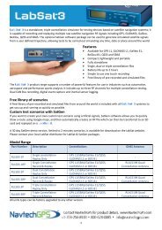
IndexSBAS 48system setup 51vector 46mounting See antenna mountingNNMEA messages 22, 42Pposition 35powerA21 specifications 57A31 specifications 58powering up the system 26specifications 55power indicator LED 27powering off the receiver 26powering on the receiver 26Rreceiverpowering off 26powering on 26receiver, mounting 20RTKconstrained heading solution 33moving base station 8use by <strong>VS131</strong> 8SSBAScoasting between corrections 35not available 6receiving corrections 35tracking 7use of 6serial portscommunicate at 22communicate with 22setup, system, menu map 51signalindicators 35lock 35lock, LED readout 35quality 35specificationsA21 environmental 57A21 L-band sensor 57A21 mechanical 57A21 power 57A31 beacon sensor 58A31 environmental 59A31 GNSS sensor 58A31 L-band sensor 58A31 mechanical 58A31 power 58beacon sensor 54communication 55environmental 56GNSS sensor 57<strong>GPS</strong> 54power 55receiver 54Ttilt aid, disabling 33time constants 34adjusting 34course-over-ground 11heading 10HRTAU 11speed 11tracking, automatic 6turn rate, limits 33Uupdates, receiving 35Vvector, menu map 46Wwizardconfiguration 30, 50configuration, using 31Key FeaturesChapter 1: IntroductionKey features of the <strong>VS131</strong> include:• High-precision positioning in L1, SBAS, beacon, and L-band (beacon andL-band require an unlock code)• Heave of 30 cm rms (D<strong>GPS</strong>)• Pitch and roll < 1° rms• Simple menu operations• Accurate heading up to 3 minutes during <strong>GPS</strong> outages• Integrated gyro and tilt sensors deliver fast startup times and provideheading updates during temporary loss of <strong>GPS</strong>What’s Included in Your KitYour <strong>VS131</strong> kit (Figure 1-1) includes the following parts:• <strong>VS131</strong> receiver and related mounting hardware• Power and data cablesNote: The standard <strong>VS131</strong> kit does not include antennas, antenna mountinghardware, and antenna cables since receiver options vary.ABFEFigure 1-1: <strong>VS131</strong> system parts diagramTable 1-1 on page 4 provides the description and part number of each part in your kit.Review the parts shipped with your kit: if any parts are damaged, contact your freightcarrier. If any parts are missing, contact your dealer.CGD<strong>Vector</strong> <strong>VS131</strong> <strong>GPS</strong> <strong>Compass</strong> User Guide 62 PN 875-0311-000 Rev B1<strong>Vector</strong> <strong>VS131</strong> <strong>GPS</strong> <strong>Compass</strong> User Guide 3 PN 875-0311-000 Rev B1
Chapter 1: IntroductionTable 1-1: Parts listItem Part <strong>Name</strong> Qty Part NumberA <strong>VS131</strong> receiver 1 803-3022-000#B Receiver mounting kit1 710-0056-000#(two brackets and related hardware)C Power cable, circular 1 054-0118-000#D Data cable, DB-9 female to DB-9 male, 3 m 1 050-0011-022#The following are available for purchase separately from the standard <strong>VS131</strong> kit.E Antenna (quantity of each based on yourpurchased configuration)FA21A31Antenna mounting kit (quantity of each based onyour purchased configuration)A21 antenna mounting kitA31 antenna mounting kitNote: Your kit may not include a mag mount.804-3036-000#804-3043-000#710-0110-000#710-0111-000#G Antenna cable, TNC male to TNC male, 10 m 2 052-0004-000#Using <strong>Vector</strong>PC to Communicate with the<strong>VS131</strong>Hemisphere <strong>GPS</strong>’ <strong>Vector</strong>PC is a free utility program that runs on your Windows PC orWindows mobile device. Simply connect your Windows device to the <strong>VS131</strong> via theCOM port and open <strong>Vector</strong>PC. The screens within <strong>Vector</strong>PC enable you to easilyinterface with the <strong>VS131</strong> to:• Select the internal SBAS, beacon, or L-band correction source, if available,and monitor reception• Configure <strong>GPS</strong> message output and port settings• Review heading, pitch, and roll visually• Help calculate heading offset or heading bias• Help calculate heading offset or heading bias<strong>Vector</strong>PC is available for download from the OEM Software Downloads page on theHemisphere <strong>GPS</strong> website (www.hemispheregps.com).IndexNumerics1 PPS output 22AA21 antennaGNSS sensor specifications 57L-band sensor specifications 57A31 antennabeacon sensor specifications 58GNSS sensor specifications 58L-band sensor specifications 58accelerometer See tilt aidantennacable, routing and securing 19mounting 16mounting, magnetic 17mounting, pole mount 18mounting, rail mount 19placement, optimal 15primary, search volume 8secondary 8Bbase station, moving, RTK 8baud rate 42beaconA31 sensor specifications 58description of 7sensor specifications 54status 35Ccablesantenna 19connecting 21selecting port, message output 22COASTcorrections from external source 42communication specifications 55configurationmenu system 29of the system 30returning to factory defaults 29wizard 30, 50wizard, using 31DD<strong>GPS</strong>status 35D<strong>GPS</strong> position indicator LED 27Diff (differential source)menu map 48disablinggyro 33tilt aid 33EenvironmentalA21 specifications 57A31 specifications 59environmental specifications 56event marker 22GGNSSA31 sensor specifications 58sensor specifications 57<strong>GPS</strong>menu map 47operation 6receiver performance 6specifications 54status 35gyro 33aiding 9calibration, self or manual 9disabling 33Hheading 14, 35bias 14heading rate time constant 11HRTAU 11LL-bandA21 sensor specifications 57A31 sensor specifications 58LEDD<strong>GPS</strong> position indicator 27indicators 27power indicator 27MmechanicalA21 specifications 57A31 specifications 58menu map 28Diff (differential source) 48<strong>GPS</strong> 46, 47<strong>Vector</strong> <strong>VS131</strong> <strong>GPS</strong> <strong>Compass</strong> User Guide 4 PN 875-0311-000 Rev B1<strong>Vector</strong> <strong>VS131</strong> <strong>GPS</strong> <strong>Compass</strong> User Guide 61 PN 875-0311-000 Rev B1
Chapter 2: Understanding the <strong>VS131</strong><strong>GPS</strong> Overview<strong>VS131</strong> Overview<strong>Vector</strong> <strong>VS131</strong> <strong>GPS</strong> <strong>Compass</strong> User Guide 5 PN 875-0311-000 Rev B1
Chapter 2: Understanding the <strong>VS131</strong><strong>GPS</strong> OverviewFor your convenience, both the <strong>GPS</strong> and SBAS operation of the <strong>VS131</strong> featuresautomatic operational algorithms. When powered for the first time, the <strong>VS131</strong>performs a “cold start,” which involves acquiring the available <strong>GPS</strong> satellites in viewand the SBAS differential service.If SBAS is not available in your area, an external source of RTCM SC-104 differentialcorrections may be used. If you use an external source of correction data, it mustsupport an eight data bit, no parity, one stop bit configuration (8-N-1).Appendix D: Technical SpecificationsTable D-19: A31 environmental specificationsSpecificationDescriptionStorage temperature-40°C to +85°C (-40°F to +185°F)Operating temperature-30°C to +70°C (-22°F to +158°F)Enclosure ratingIP69KShock and vibration EP 455Humidity95%, non-condensing<strong>GPS</strong> OperationThe <strong>GPS</strong> receiver is always operating, regardless of the D<strong>GPS</strong> mode of operation. Thefollowing sections describe the general operation of the <strong>VS131</strong>’s internal <strong>GPS</strong> receiver.Note: Differential source have no impact on heading, pitch, or roll. It only has animpact on positioning and heave.Automatic TrackingThe <strong>VS131</strong>’s internal <strong>GPS</strong> receiver automatically searches for <strong>GPS</strong> satellites, acquiresthe signals, and manages the navigation information required for positioning andtracking.Receiver PerformanceThe <strong>VS131</strong> works by finding four or more <strong>GPS</strong> satellites in the visible sky. It usesinformation from the satellites to compute a position within 2.5 m. Since there issome error in the <strong>GPS</strong> data calculations, the <strong>VS131</strong> also tracks a differential correction.The <strong>VS131</strong> uses these corrections to improve its position accuracy to better than0.6 m.There are two main aspects of <strong>GPS</strong> receiver performance:• Satellite acquisition• Positioning and heading calculationWhen the <strong>VS131</strong> is properly positioned, the satellites transmit coded information tothe antennas on a specific frequency. This allows the receiver to calculate a range toeach satellite from both antennas. <strong>GPS</strong> is essentially a timing system. The ranges arecalculated by timing how long it takes for the signal to reach the <strong>GPS</strong> antenna. The<strong>GPS</strong> receiver uses a complex algorithm incorporating satellite locations and ranges toeach satellite to calculate the geographic location and heading. Reception of any fouror more <strong>GPS</strong> signals allows the receiver to compute three-dimensional coordinatesand a valid heading.Differential OperationThe purpose of differential <strong>GPS</strong> (D<strong>GPS</strong>) is to remove the effects of selectiveavailability (SA), atmospheric errors, timing errors, and satellite orbit errors, whileenhancing system integrity.Autonomous positioning capabilities of the <strong>VS131</strong> will result in positioning accuraciesof 2.5 m 95% of the time. To improve positioning quality to sub-meter levels, the<strong>VS131</strong> is able to use differential corrections received through the internal SBASdemodulator or externally-supplied RTCM corrections.<strong>Vector</strong> <strong>VS131</strong> <strong>GPS</strong> <strong>Compass</strong> User Guide 6 PN 875-0311-000 Rev B1<strong>Vector</strong> <strong>VS131</strong> <strong>GPS</strong> <strong>Compass</strong> User Guide 59 PN 875-0311-000 Rev B1
Appendix D: Technical SpecificationsA31 Antenna SpecificationsTable D-14 through Table D-19 list the technical specifications of the A31 antenna.Table D-14: A31 GNSS sensor specificationsSpecificationDescriptionGNSS reception<strong>GPS</strong>, SBAS, L-band, and beaconGNSS frequency1.575 GHz (L1)LNA gain30 dBLNA noise< 2.0 dBTable D-15: A31 L-Band sensor specificationsSpecificationDescriptionL-Band frequency1.525 - 1.585 GHzL-Band LNA gain30 dBTable D-16: A31 Beacon sensor specificationsSpecificationDescriptionBeacon frequency283.5 - 325 kHzBeacon LNA gain30 dBChapter 2: Understanding the <strong>VS131</strong>In addition to these differential services the <strong>VS131</strong> can also receive radiobeaconcorrections.For more information on the differential services and the associated commands referto the Hemisphere <strong>GPS</strong> Technical Reference (go to www.hemispheregps.com and clickthe <strong>GPS</strong> Reference icon).Automatic SBAS TrackingThe <strong>VS131</strong> automatically scans and tracks SBAS signals without the need to tune thereceiver. The <strong>VS131</strong> features two-channel tracking that provides an enhanced ability tomaintain a lock on an SBAS satellite when more than one satellite is in view. Thisredundant tracking approach results in more consistent tracking of an SBAS signal inareas where signal blockage of a satellite is possible.Beacon OperationMany marine authorities, such as coast guards, have installed networks ofradiobeacons that broadcast D<strong>GPS</strong> corrections to users of this system. With theincreasing utility of these networks for terrestrial applications, there is an increasingtrend toward densification of these networks inland. The dual channel beacon receiverin the <strong>VS131</strong> can operate in manual or automatic tuning mode, or, using databasemode, will select the closest station in compliance with IEC 61108-4 standards.L-BandL-band corrections are available worldwide through third-party providers. With thisservice, the positioning accuracy does not degrade as a function of distance to a basestation, as the data content is not composed of a single base station’s information, butan entire network’s information.Table D-17: A31 power specificationsSpecificationInput voltageInput currentDescription5 to 12 VDC50 to 60 mATable D-18: A31 mechanical specificationsSpecificationEnclosureDimensionsWeightMounting threadConnectorDescriptionLexan10.4 H x 14.5 D (cm)4.1 H x 5.7 D (in)734 g (25.9 oz)1" coarse thread (5/8" adapter available)TNC<strong>Vector</strong> <strong>VS131</strong> <strong>GPS</strong> <strong>Compass</strong> User Guide 58 PN 875-0311-000 Rev B1<strong>Vector</strong> <strong>VS131</strong> <strong>GPS</strong> <strong>Compass</strong> User Guide 7 PN 875-0311-000 Rev B1
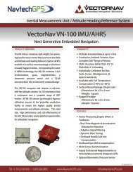
Chapter 2: Understanding the <strong>VS131</strong><strong>VS131</strong> OverviewThe <strong>VS131</strong> provides accurate and reliable heading and position information at highupdate rates. To accomplish this task, the <strong>VS131</strong> uses a high performance <strong>GPS</strong>receiver and two antennas for <strong>GPS</strong> signal processing. One antenna is designated asthe primary <strong>GPS</strong> antenna and the other is the secondary <strong>GPS</strong> antenna. Positionscomputed by the <strong>VS131</strong> are referenced to the phase center of the primary <strong>GPS</strong>antenna. Heading data references the vector formed from the primary <strong>GPS</strong> antennaphase center to the secondary <strong>GPS</strong> antenna phase center.Fixed Baseline Moving Base Station RTKThe <strong>VS131</strong>’s internal <strong>GPS</strong> receiver uses both the L1 <strong>GPS</strong> C/A code and carrier phasedata to compute the location of the secondary <strong>GPS</strong> antenna in relation to the primary<strong>GPS</strong> antenna with a very high sub-centimeter level of precision. The technique ofcomputing the location of the secondary <strong>GPS</strong> antenna with respect to the primaryantenna, when the primary antenna is moving, is often referred to as moving basestation Real Time Kinematic (or moving base station RTK).Generally, RTK technology is very sophisticated and requires a significant number ofpossible solutions to be analyzed where various combinations of integer numbers ofL1 wavelengths to each satellite intersect within a certain search volume. The integernumber of wavelengths is often referred to as the “ambiguity” as they are initiallyambiguous at the start of the RTK solution.The <strong>VS131</strong> restricts the RTK solution by knowing that the secondary <strong>GPS</strong> antenna is afixed distance from the primary <strong>GPS</strong> antenna. The default value is 1.0 m, but you mayinstall the antennas with a different separation distance, then enter that value into the<strong>VS131</strong>. This is called a fixed baseline and it defines the search volume of thesecondary antenna as the surface of a sphere with radius 1.0 m centered on thelocation of the primary antenna (see Figure 2-1).A21 Antenna SpecificationsAppendix D: Technical SpecificationsTable D-9 through Table D-13 list the technical specifications of the A21 antenna.Table D-9: A21 GNSS sensor specificationsSpecificationDescriptionGNSS reception<strong>GPS</strong>, SBAS, and L-bandGNSS frequency1.575 GHz (L1)LNA gain30 dBLNA noise< 2.0 dBTable D-10: A21 L-Band sensor specificationsSpecificationDescriptionL-Band frequency1.525 - 1.585 GHzL-Band LNA gain30 dBTable D-11: A21 power specificationsSpecificationDescriptionInput voltage3.3 to 12 VDCInput current24 mA, typicalTable D-12: A21 mechanical specificationsPrimary antennaSpecificationEnclosureDimensionsWeightMounting threadRF connectorDescriptionAluminum base with ASA plastic cap7.0 H x 13.0 D (cm)2.8 H x 5.1 D (in)380 g (13.4 oz)5/8” female threadTNC1.0 m baselineFigure 2-1: Secondary antenna’s search volumeNote: The <strong>VS131</strong> moving base station algorithm only uses <strong>GPS</strong> to calculate heading.Differential and RTK corrections are not used in this calculation and will not affectheading accuracy.Table D-13: A21 environmental specificationsSpecificationDescriptionOperating temperature-30°C to +70°C (-22°F to +158°F)Storage temperature-40°C to +85°C (-40°F to +185°F)Enclosure ratingIP69KShock and vibrationEP455Humidity96% non condensing<strong>Vector</strong> <strong>VS131</strong> <strong>GPS</strong> <strong>Compass</strong> User Guide 8 PN 875-0311-000 Rev B1<strong>Vector</strong> <strong>VS131</strong> <strong>GPS</strong> <strong>Compass</strong> User Guide 57 PN 875-0311-000 Rev B1
Appendix D: Technical SpecificationsTable D-6: <strong>VS131</strong> environmental specificationsItemOperating temperatureSpecification-30°C to +70°C (-22°F to +158°F)Storage temperature-40°C to +85°C (-40°F to +185°F)Humidity95%, non-condensingEnclosure rating IP66 (IEC 60529)Shock and vibration Mechanical Shock: EP455 Section 5.14.1Vibration: EP455 Section 5.15.1 RandomEMC CE (IEC 60945 Emissions and Immunity), FCC Part 15,Subpart B, CISPR 22IMO wheelmarked certification NoTable D-7: <strong>VS131</strong> mechanical specificationsItemDimensionsWeightStatus indications (LEDs)Power switchPower connectorData connectorsAntenna connectorsSpecification20.2 L x 12.0 W x 7.5 H (cm)8.0 L x 4.7 W x 3.0 H (in)~1.1 kg (2.5 lb)Power, primary <strong>GPS</strong> lock, secondary <strong>GPS</strong> lock, differentiallock, D<strong>GPS</strong> position, heading, L-band lockFront panel soft switch2-pin ODU metal circular(2) DB9 sealed(2) TNC femaleSupplemental SensorsChapter 2: Understanding the <strong>VS131</strong>The <strong>VS131</strong> has an integrated gyro and two tilt sensors, which are enabled by default.Each supplemental sensor may be individually enabled or disabled. Bothsupplemental sensors are mounted on the printed circuit board inside the <strong>VS131</strong>.The sensors act to reduce the RTK search volume, which improves heading startupand reacquisition times. This improves the reliability and accuracy of selecting thecorrect heading solution by eliminating other possible, erroneous solutions.The Hemisphere <strong>GPS</strong> Technical Reference (go to www.hemispheregps.com and clickthe <strong>GPS</strong> Reference icon) describes the commands and methodology required torecalibrate, query, or change the sensors status.Tilt AidingThe <strong>VS131</strong>’s accelerometers (internal tilt sensors) are factory calibrated and enabledby default. This constrains the RTK heading solution beyond the volume associatedwith just a fixed antenna separation. This is because the <strong>VS131</strong> knows theapproximate inclination of the secondary antenna with respect to the primaryantenna. The search space defined by the tilt sensor will be reduced to a horizontalring on the sphere’s surface by reducing the search volume. This considerablydecreases startup and reacquisition times (see Figure 2-2).Tilt angleTable D-8: Aiding devicesItemGyroTiltSensorsSpecificationProvides smooth heading, fast heading reacquisition, and reliable < 1˚ perminute heading for periods up to 3 minutes when loss of <strong>GPS</strong> has occurred. 5Provide pitch, roll data and assist in fast start-up and reacquisition of headingsolution.1 Depends on multipath environment, number of satellites in view, and satellite geometryFigure 2-2: <strong>VS131</strong>’s tilt aidingGyro AidingThe <strong>VS131</strong>’s internal gyro offers several benefits. It reduces the sensor volume for anRTK solution. This shortens reacquisition times when a <strong>GPS</strong> heading is lost becausethe satellite signals were blocked. The gyro provides a relative change in angle sincethe last computed heading, and, when used in conjunction with the tilt sensor, definesthe search space as a wedge-shaped location (see Figure 2-3).2 Requires a subscription from L-band service provider3 Based on a 40 second time constant4 Hemisphere <strong>GPS</strong> proprietary5 Under static conditionsFigure 2-3: <strong>VS131</strong>’s gyro aiding<strong>Vector</strong> <strong>VS131</strong> <strong>GPS</strong> <strong>Compass</strong> User Guide 56 PN 875-0311-000 Rev B1<strong>Vector</strong> <strong>VS131</strong> <strong>GPS</strong> <strong>Compass</strong> User Guide 9 PN 875-0311-000 Rev B1
Chapter 2: Understanding the <strong>VS131</strong>Appendix D: Technical SpecificationsThe gyro aiding accurately smoothes the heading output and the rate of turn. Itprovides an accurate substitute heading for a short period depending on the roll andpitch of the vessel, ideally seeing the system through to reacquisition. The gyroprovides an alternate source of heading, accurate to within 1º per minute for up tothree minutes, in times of <strong>GPS</strong> loss for either antenna. If the outage lasts longer thanthree minutes, the gyro will have drifted too far and the <strong>VS131</strong> begins outputting nullfields in the heading output messages. There is no user control over the timeoutperiod of the gyro.The gyro initializes itself at powerup and during initialization, or you can calibrate it asoutlined in the Hemisphere <strong>GPS</strong> Technical Reference (go to www.hemispheregps.comand click the <strong>GPS</strong> Reference icon). When the gyro is first initializing, it is important thatthe dynamics that the gyro experiences during this warmup period are similar to theregular operating dynamics. For example, if you use the <strong>VS131</strong> on a high speed,maneuverable craft, it is essential that when gyro aiding in the <strong>VS131</strong> is first turnedon, use it in an environment that has high dynamics for the first five to ten minutesinstead of sitting stationary.With the gyro enabled, the gyro is also used to update the post HTAU smoothedheading output from the moving base station RTK <strong>GPS</strong> heading computation. Thismeans that if the HTAU value is increased while gyro aiding is enabled, there will belittle to no lag in heading output due to vehicle maneuvers. The Hemisphere <strong>GPS</strong>Technical Reference includes information on setting an appropriate HTAU value for theapplication.Time ConstantsThe <strong>VS131</strong> incorporates user-configurable time constants that can provide a degree ofsmoothing to the heading, pitch, rate of turn (ROT), course over ground (COG), andspeed measurements. You can adjust these parameters depending on the expecteddynamics of the vessel. For example, increasing the time is reasonable if the vessel isvery large and is not able to turn quickly or would not pitch quickly. The resultingvalues would have reduced ‘noise,’ resulting in consistent values with time. However,if the vessel is quick and nimble, increasing this value can create a lag inmeasurements. Formulas for determining the level of smoothing are located in theHemisphere <strong>GPS</strong> Technical Reference (go to www.hemispheregps.com and click the<strong>GPS</strong> Reference icon). If you are unsure on how to set this value, it is best to beconservative and leave it at the default setting.Heading Time ConstantUse the $JATT,HTAU command to adjust the level of responsiveness of the trueheading measurement provided in the $GPHDT message. The default value of thisconstant is 2.0 seconds of smoothing when the gyro is enabled. The gyro is enabledby default, but can be turned off. By turning the gyro off, the equivalent default valueof the heading time constant would be 0.5 seconds of smoothing. This is notautomatically done and therefore you must manually enter it. Increasing the timeconstant increases the level of heading smoothing and increases lag.Table D-3: <strong>VS131</strong> L-band sensor specificationsItemSensitivityChannel spacingSatellite selectionReacquisition timeRejectionProcessorCommand supportSpecificationTable D-4: <strong>VS131</strong> communication specificationsItem-130 dBm7.5 kHzManual and automatic15 seconds (typical)15 kHz spacing > 30 dB300 kHz spacing > 60 dBDSP for demodulation and protocol decoding moduleprovides processing for differential algorithmsReports L-band region and satellite informationAllows input and status of L-band subscription, bit error rate(BER) output for reception quality indication, and manualfrequency tuningSpecificationSerial ports2 full-duplex RS-232USB ports1 USB-BBaud rates 4800 - 115200Data I/O protocol NMEA 0183, Crescent binary 4Correction I/O protocol RTCM v2.3 (D<strong>GPS</strong>), RTCM SC-104, L-Dif 4Timing output1 PPS CMOS, active high, rising edge sync, 10 k, 10 pF loadTable D-5: <strong>VS131</strong> power specificationsItemPower input voltagePower consumptionCurrent consumptionPower isolationReverse polarity protectionAntenna short circuitprotectionSpecification8 to 36 VDC< 4.5 W nominal (L1 <strong>GPS</strong> and L-band)< 3.6 W nominal (L1 <strong>GPS</strong>)< 0.38 A nominal (L1 <strong>GPS</strong> and L-band)< 0.30 A nominal (L1 <strong>GPS</strong>)500 VYesYesPitch Time ConstantUse the $JATT,PTAU command to adjust the level of responsiveness of the pitchmeasurement provided in the $PSAT,HPR message. The default value of this constantis 0.5 seconds of smoothing. Increasing the time constant increases the level of pitchsmoothing and increases lag.<strong>Vector</strong> <strong>VS131</strong> <strong>GPS</strong> <strong>Compass</strong> User Guide 10 PN 875-0311-000 Rev B1<strong>Vector</strong> <strong>VS131</strong> <strong>GPS</strong> <strong>Compass</strong> User Guide 55 PN 875-0311-000 Rev B1
Appendix D: Technical Specifications<strong>VS131</strong> Receiver SpecificationsTable D-1 through Table D-7 list the technical specifications of the <strong>VS131</strong>.Table D-1: <strong>VS131</strong> <strong>GPS</strong> sensor specificationsItemSpecificationRMS (67%) 2DRMS (95%)Receiver typeL1, C/A code, with carrier phase smoothingSignals received<strong>GPS</strong>Channels 24<strong>GPS</strong> sensitivity-142 dBmSBAS tracking2-channel, parallel trackingUpdate rate10 Hz standard, 20 Hz available by subscriptionHorizontal accuracyAutonomous, no SA 1 1.2 m 2.5 mL-band D<strong>GPS</strong> service 1,2SBAS (WAAS) 1Beacon 10.3 m0.3 m0.3 m0.6 m0.6 m0.6 mHeading accuracy< 0.33˚ rms @ 0.5 m antenna separation< 0.17˚ rms @ 1.0 m antenna separation< 0.08˚ rms @ 2.0 m antenna separation< 0.03˚ rms @ 5.0 m antenna separationPitch/roll accuracy< 1º rmsHeave accuracy 30 cm rms 3Timing (1PPS) accuracy 50 nsRate of turn90º/s maximumCold start time< 60 s typical (no almanac or RTC)Warm start time< 20 s typical (almanac and RTC)Hot start time< 1 s (almanac, RTC, and position)Heading fix< 10 s typical (valid position)Maximum speed1,850 kph (999 kts)Maximum altitude 18,288 m (60,000 ft)Chapter 2: Understanding the <strong>VS131</strong>Rate of Turn (ROT) Time ConstantUse the $JATT,HRTAU command to adjust the level of responsiveness of the ROTmeasurement provided in the $GPROT message. The default value of this constant is2.0 seconds of smoothing. Increasing the time constant increases the level of ROTsmoothing.Course Over Ground (COG) Time ConstantUse the $JATT,COGTAU command to adjust the level of responsiveness of the COGmeasurement provided in the $GPVTG message. The default value of this constant is0.0 seconds of smoothing. Increasing the time constant increases the level of COGsmoothing. COG is computed using only the primary <strong>GPS</strong> antenna and its accuracydepends upon the speed of the vessel (noise is proportional to 1/speed). This value isinvalid when the vessel is stationary.Speed Time ConstantUse the $JATT,SPDTAU command to adjust the level of responsiveness of the speedmeasurement provided in the $GPVTG message. The default value of this parameteris 0.0 seconds of smoothing. Increasing the time constant increases the level of speedmeasurement smoothing.Table D-2: <strong>VS131</strong> beacon sensor specificationsItemChannelsFrequency rangeOperating modesComplianceSpecification2-channel, parallel tracking283.5 to 325 kHzManual, automatic, and databaseIEC 61108-4 beacon standard<strong>Vector</strong> <strong>VS131</strong> <strong>GPS</strong> <strong>Compass</strong> User Guide 54 PN 875-0311-000 Rev B1<strong>Vector</strong> <strong>VS131</strong> <strong>GPS</strong> <strong>Compass</strong> User Guide 11 PN 875-0311-000 Rev B1
Appendix D: Technical Specifications<strong>VS131</strong> Receiver SpecificationsA21 Antenna SpecificationsA31 Antenna Specifications<strong>Vector</strong> <strong>VS131</strong> <strong>GPS</strong> <strong>Compass</strong> User Guide 53 PN 875-0311-000 Rev B1
Chapter 3: Installing the <strong>VS131</strong>Mounting the AntennasMounting the ReceiverRouting and Connecting the CablesConnecting the Receiver to External DevicesDefault Parameters<strong>Vector</strong> <strong>VS131</strong> <strong>GPS</strong> <strong>Compass</strong> User Guide 13 PN 875-0311-000 Rev B1
Chapter 3: Installing the <strong>VS131</strong>Mounting the AntennasHemisphere <strong>GPS</strong> recommends mounting the antennas first then the mounting thereceiver. When mounting the antennas consider the following:• Mounting orientation (parallel or perpendicular)• Proper antenna placement• Mounting options (magnetic, pole, or rail mounting)Antenna OptionsThe standard <strong>VS131</strong> kit does not include antennas. Your <strong>VS131</strong> kit may contain one ofeach or two of one of the following antennas: A21 and A31. For example:• If you will be using beacon, your kit may include one A31 beacon antennaand one A21 antenna.• If you will not be using beacon, your kit may include two A21 antennas.Mounting OrientationThe <strong>VS131</strong> outputs heading, pitch, and roll readings regardless of the orientation ofthe antennas. However, the relation of the antennas to the boat’s axis determineswhether you will need to enter a heading, pitch, or roll bias. The primary antenna isused for positioning and the primary and secondary antennas, working inconjunction, output heading, pitch, and roll values.Regardless of which mounting orientation you use, the <strong>VS131</strong> provides the ability tooutput the heave of the vessel. This output is available via the $GPHEV message. Formore information on this message refer to the Hemisphere <strong>GPS</strong> Technical Reference(go to www.hemispheregps.com and click the <strong>GPS</strong> Reference icon).Parallel OrientationThe most common installation is to orient the antennas parallel to, and along thecenterline of, the axis of the boat. This provides a true heading. In this orientation:• If you use a gyrocompass, you can enter a heading bias in the <strong>VS131</strong> tocalibrate the physical heading to the true heading of the vessel.• You may need to adjust the pitch/roll output to calibrate the measurement ifthe <strong>Vector</strong> is not installed in a horizontal plane.System Setup MenuAppendix C: Menu MapThe System Setup menu allows you quickly view and edit current system settings.General settings include such items as current applications, units, baud rates, logs,LED contrast, subscription code, display orientation (you can flip the display 180° byselecting YES under Flip Display), and language.Figure C-8: System Setup menuPerpendicular OrientationYou can also install the antennas so they are oriented perpendicular to the centerlineof the boat’s axis. In this orientation:• You will need to enter a heading bias of +90° if the primary antenna is on thestarboard side of the boat and -90° if the primary antenna is on the port sideof the boat.• You will need to configure the receiver to specify the <strong>GPS</strong> antennas aremeasuring the roll axis using $JATT,ROLL,YES.• You will need to enter a roll bias to properly output the pitch and roll values.• You may need to adjust the pitch/roll output to calibrate the measurement ifthe <strong>Vector</strong> is not installed in a horizontal plane.<strong>Vector</strong> <strong>VS131</strong> <strong>GPS</strong> <strong>Compass</strong> User Guide 14 PN 875-0311-000 Rev B1<strong>Vector</strong> <strong>VS131</strong> <strong>GPS</strong> <strong>Compass</strong> User Guide 51 PN 875-0311-000 Rev B1
Appendix C: Menu MapFigure C-6: Autonomous menuPlanning the Optimal Antenna PlacementChapter 3: Installing the <strong>VS131</strong>Note: In the <strong>VS131</strong> kit, install the A21 antenna as the primary antenna as it is used forpositioning.Proper antenna placement is important to obtain a high-precision <strong>GPS</strong> reading. Forthe best results, orient the antennas so the antennas’ connectors face the samedirection. Also, place the antennas:• With a clear view of the horizon• Away from other electronics and antennas• Along the vessel’s centerlineYou must install the primary antenna along the vessel’scenterline; you cannot adjust the position readings if the primary antenna isinstalled off the centerline. Positions are computed for the primary antenna.Config Wizard MenuFigure C-7: External RTCM menuThe Config Wizard walks you through basic settings to get up and running. See“Config Wizard Menu” on page 30 to view the Config Wizard menu map.• On a level plane• With a 5.0 m maximum separation (default is 1.0 m)• Away from radio frequencies• As high as possibleSet the MSEP value to be accurate to within 1 to 2 cm. For more information on MSEPrefer to the Hemisphere <strong>GPS</strong> Technical Reference (go to www.hemispheregps.comand click the <strong>GPS</strong> Reference icon).See Figure 3-1 below through Figure 3-3 on page 16 for mounting orientationexamples.P = primary antenna (A21)S = secondary antenna (A21 or A31*)*must be A31 if using beacon-H+PSForwardmotionReceiver(display mustface primaryantenna)P+R-R-P+HAntennaseparation(1.0 m default,5.0 m maximum)Figure 3-1: Recommended orientation and resulting signs of HPR values<strong>Vector</strong> <strong>VS131</strong> <strong>GPS</strong> <strong>Compass</strong> User Guide 50 PN 875-0311-000 Rev B1<strong>Vector</strong> <strong>VS131</strong> <strong>GPS</strong> <strong>Compass</strong> User Guide 15 PN 875-0311-000 Rev B1
Chapter 3: Installing the <strong>VS131</strong>Appendix C: Menu MapP = primary antenna (A21)S = secondary antenna (A21 or A31*)*must be A31 if using beacon-H+RSReceiver(display mustface primaryantenna)ForwardmotionPFigure 3-2: Alternate orientation and resulting signs of HPR values+P-P-R+HAntennaseparation(1.0 m default,5.0 m maximum)Beacon onlyappears if RTCM2 isset to YESFigure C-4: Beacon menuCenterlineFigure 3-3: Antenna installation: Cross-section of boatMounting OptionsYou can mount the antennas with a magnetic mount, pole mount, or rail mountconfiguration. You can secure the antennas to a threaded pole or threaded mountusing the included mounting adapters.Depending on the antennas included in your kit, you may need to use the includedantenna height adapters to bring the antennas level. If the adapter is not used, youwill need to enter a non-level bias calculation into the system (see “Q: I could notinstall my antennas at the same height. How do I calibrate for the height offset?” onpage 43 of Appendix B, “FAQ.”)The maximum allowable antenna separation is 5.0 m. Any greaterdistance may result in an incorrect heading.L-Band only appears ifOMNIVBS and/orOMNIHP are set to YESFigure C-5: L-band menu<strong>Vector</strong> <strong>VS131</strong> <strong>GPS</strong> <strong>Compass</strong> User Guide 16 PN 875-0311-000 Rev B1<strong>Vector</strong> <strong>VS131</strong> <strong>GPS</strong> <strong>Compass</strong> User Guide 49 PN 875-0311-000 Rev B1
Appendix C: Menu MapDifferential MenuUse the Differential menu to view or change your differential settings. The followingavailable differential sources depend on the configuration you purchased.• SBAS• Beacon (RTCM2) - available with purchased unlock code• L-band (OMNIVBS, OMNIHP) - available with purchased unlock code• None (Autonomous)To select the differential source:1. Press Differential > Include then set each format you may use to Yes. Forexample, if you will be using Beacon, set RTCM2 to Yes.2. Press Back to return to the previous menu level, press InUse, then selectyour preferred differential source. For example, if you will be using Beacon,select Beacon (RTCM2 will be displayed when finished).Figure C-3 through Figure C-8 show the complete menu maps forthe SBAS, Beacon, L-band, and Autonomous, respectively. TheInclude menu (at right) in each of these figures shows all availableformats. If you have not purchased unlock codes for L-band andBeacon, the OMNIVBS/OMNIHP (L-band) and RTCM2 (Beacon)menu items will not appear on your menu.Figure C-3: SBAS menuChapter 3: Installing the <strong>VS131</strong>Magnetic MountingThe following procedure assumes your kit contains one A31 beacon antenna and oneA21 antenna. If your kit contains two A21 antennas (no beacon), mount both antennasin the same manner as outlined in the steps for the A21.Note: Your kit may not include a magnetic mount.You can screw the magnetic mount into the bottom of the antenna and mount it to anymetal surface. If there are no metal surfaces, use the zinc disc and foam adhesiveincluded in your kit to mount the antenna.To mount the antennas using the magnetic mount:1. Select a location and orientation that meet therequirements outlined in “Mounting Orientation”on page 14 and “Planning the Optimal AntennaPlacement” on page 15.2. A21 antenna only: Unlike the A31, the A21antenna does not include a threaded mountinghole. You must attach the mounting bracket (see atright) using the four screws in your kit.3. Attach the magnetic mount extension to themagnetic base plate.Note: Photos at right and instep 4 show the zinc discattached to the magnetic baseplate. You will only need thezinc disc if mounting theantenna to a non-metal surface(see steps 6 through 11).4. Thread the magnetic mount into the mounting bracket on the bottom of theA21 antenna or into the bottom of the A31 antenna.When threading the magnetic mounts, hand tighten only.Damage resulting from over-tightening may void your warranty.A21A31If you are mounting the antenna on a metal surface, go to step 5.If you are mounting the antenna on a non-metal surface and need to use themetal disc and foam adhesive, skip step 5 and complete steps 6 through 11.<strong>Vector</strong> <strong>VS131</strong> <strong>GPS</strong> <strong>Compass</strong> User Guide 48 PN 875-0311-000 Rev B1<strong>Vector</strong> <strong>VS131</strong> <strong>GPS</strong> <strong>Compass</strong> User Guide 17 PN 875-0311-000 Rev B1
Chapter 3: Installing the <strong>VS131</strong>5. Place the antenna in the desired location, ensuring the antenna is secure inits mounting position (end of metal surface mounting procedure).6. Clean and dry the surface where you will attach the zinc disc.7. Remove the backing from one side of thefoam adhesive and press the adhesiveonto the zinc plate (at right).8. Remove the backing from the other sideof the foam adhesive and press the zincdisc onto the mounting surface on thevessel, applying firm pressure to ensure good adhesion.9. Place the antenna on top of the zinc disc, ensuring the antenna is secure inits mounting position.Pole MountingThe following procedure assumes your kit contains one A31 beacon antenna and oneA21 antenna. If your kit contains two A21 antennas (no beacon), mount both antennasin the same manner as outlined in the steps for the A21.You can pole-mount theantennas using existing hardware on your vessel.To mount the antennas using a pole mount:1. Select a location and orientation that meet therequirements outlined in “Mounting Orientation”on page 14 and “Planning the Optimal AntennaPlacement” on page 15.2. A21 antenna only: Unlike the A31, the A21antenna does not include a threaded mountinghole. You must attach the mounting base using thefour screws included in your kit (see at right).3. Thread the pole mount (not included) into themounting bracket on the bottom of the A21antenna or into the bottom of the A31 antenna.<strong>GPS</strong> MenuAppendix C: Menu MapUse the <strong>GPS</strong> menu to view and edit your <strong>GPS</strong> settings. Settings include the data portoutputs, specific positioning parameters, UTC time offset, and satellite visibility andpositioning information. Figure C-2: <strong>GPS</strong> menuA21A31When threading the pole mounts, hand tighten only. Damageresulting from over-tightening may void your warranty.4. Mark and drill any mounting holes necessary for the pole mounts.<strong>Vector</strong> <strong>VS131</strong> <strong>GPS</strong> <strong>Compass</strong> User Guide 18 PN 875-0311-000 Rev B1<strong>Vector</strong> <strong>VS131</strong> <strong>GPS</strong> <strong>Compass</strong> User Guide 47 PN 875-0311-000 Rev B1
Appendix C: Menu MapChapter 3: Installing the <strong>VS131</strong>This appendix shows the complete menu map for each menu (listed below) on the<strong>VS131</strong> Top menu:• <strong>Vector</strong>• <strong>GPS</strong>• Diff (differential)• Config Wizard• System Setup<strong>Vector</strong> MenuUse the <strong>Vector</strong> menu to view and adjust <strong>Vector</strong> settings. Options vary depending onwhether you select Pitch or Roll and include such items as aiding features, timeconstants, heading bias, and antenna separation.Rail MountingYou can rail mount the antennas using existing hardware on your vessel.To rail mount the antennas:1. Select a location and orientation that meet the requirements listed in“Mounting Orientation” on page 14 and “Planning the Optimal AntennaPlacement” on page 15.2. Use appropriate hardware to securely attach the antenna to the railing.Routing and Securing the Antenna CableThe <strong>VS131</strong> receiver provides 5 VDC across the antenna ports.Connection to incompatible devices may damage equipment.To route and secure the antenna cables, review the following guidelines. The twoenclosed antennas each require a 50 impedance antenna extension cable, such asRG-58U (up to a maximum of 15 m (49 ft.) in length), for proper operation.• The <strong>GPS</strong> receiver inside the <strong>VS131</strong> requires a minimum input gain of 10 dB(and maximum of 40 dB before saturation will occur). The antennas offer28 dB of gain, so the loss budget to accommodate for cable losses is 18 dB.• Regardless of the cable material and length you choose, ensure the cablelosses are less than 18 dB of attenuation. Due to variances in the antennagain and practical attenuation of cable materials and connectors,Hemisphere <strong>GPS</strong> recommends reducing this budget to 15 dB; this budget ispresent to overcome the resulting attenuation of an RF cable.• When deciding on an antenna location, consider the amount of cablerequired: a longer cable of the same material will result in a higher loss thana shorter one. If the overall loss of the longer cable exceeds 15 dB, changethe cable material (this normally means a more expensive material that hasa larger diameter and less flexibility). The standard cables included with the<strong>VS131</strong> are of the RG58 material family and their attenuation is ~0.8 dB/m.Including connector losses, the nominal loss of these RF cables is ~10 dB,which is within the tolerable loss budget. If a 15 m or 20 m cable run isrequired, a RG8 variety is available. If lengths longer than 20 m are required,more sophisticated materials are required.For more information on cable length or low-loss cable, contact your dealer orHemisphere <strong>GPS</strong> Technical Support. Table 3-1 provides a summary of readily availablecable materials with 50 impedance.Table 3-1: Cable losses (not including connector losses)MaterialRG58RG8Times Microwave LMR400Loss at <strong>GPS</strong> L1 (1.575 GHz)0.78 dB/m0.36 dB/m0.15 dB/mFigure C-1: <strong>Vector</strong> menuFor additional cable guidelines see “Routing and Connecting the Cables” on page 21.<strong>Vector</strong> <strong>VS131</strong> <strong>GPS</strong> <strong>Compass</strong> User Guide 46 PN 875-0311-000 Rev B1<strong>Vector</strong> <strong>VS131</strong> <strong>GPS</strong> <strong>Compass</strong> User Guide 19 PN 875-0311-000 Rev B1
Chapter 3: Installing the <strong>VS131</strong>Mounting the ReceiverHemisphere <strong>GPS</strong> recommends mounting the antennas first and then the mountingthe receiver. Use the enclosed kit to mount the receiver. When mounting the <strong>VS131</strong>receiver, adhere to the following guidelines:• Install the receiver inside and away from the elements and in a location thatminimizes vibration, shock, extreme temperatures, and moisture• Position the receiver horizontally with its display facing the primary antenna• Ensure the front panel (menu screen, LEDs, buttons) is visible and accessible• Ensure the back panel (ports, connectors) is easily accessible to connect/switch out cablesFigure 3-4 shows the dimensions (including attached mounting brackets) of the <strong>VS131</strong>.Use Figure 3-4 when using the receiver mounting procedure that follows.5.2 mm4 x0.20 in134.6 mm5.30 in114.3 mm4.50 inAppendix C: Menu Map141.6 mm5.57 in119.4 mm4.70 in201.4 mm7.93 in<strong>Vector</strong> Menu<strong>GPS</strong> MenuDifferential MenuConfig Wizard MenuSystem Setup Menu74.9mm2.95 in74.9mm2.95 in114.3 mm4.50 in152.4 mm6.00 inFigure 3-4: <strong>VS131</strong> dimensions with mounting bracketsTo mount the receiver:1. Locate the thumbscrews, nuts, and brackets included in your kit.2. Slide the nuts through theopening (circled at right) alongboth sides of the receiver.<strong>Vector</strong> <strong>VS131</strong> <strong>GPS</strong> <strong>Compass</strong> User Guide 20 PN 875-0311-000 Rev B1<strong>Vector</strong> <strong>VS131</strong> <strong>GPS</strong> <strong>Compass</strong> User Guide 45 PN 875-0311-000 Rev B1
Chapter 3: Installing the <strong>VS131</strong>3. Place the bracket alongside thereceiver and insert thethumbscrews (twothumbscrews per bracket) sothey screw into the nuts.4. Using the remaining holes inthe brackets (two holes perbracket) screw down thebrackets in the desiredlocation.Remaining bracket holesNote: Hemisphere <strong>GPS</strong> doesnot provide the screws inthis step.Remaining bracket holesRouting and Connecting the CablesAdhere to the following when routing and connecting cables:• Power cable must reach an appropriate power source• Antenna cables must reach from the antennas to the receiver• Data cable may connect to a data storage device, computer, or other devicethat accepts GNSS data• Do not run cable in areas of excessive heat• Do not expose cable to corrosive chemicals• Do not crimp or excessively bend cable• Do not place tension on cable• Coil up excess cable near unit• Secure along the cable route using plastic tie wraps as necessary• Do not run cable near high voltage or strong RF noise and transmittersources• When connecting the power cable to the power source, ensure the powersource is between 8 V and 36 VImproperly installed cables near machinery can be dangerous.<strong>Vector</strong> <strong>VS131</strong> <strong>GPS</strong> <strong>Compass</strong> User Guide 21 PN 875-0311-000 Rev B1
Chapter 3: Installing the <strong>VS131</strong>Connecting the Receiver to External DevicesYou can connect the <strong>VS131</strong> to external devices via Port A and Port B on the back of thereceiver.Figure 3-5: <strong>VS131</strong> port connectionsFigure 3-6 shows the pinouts and Table 3-2 provides pinout descriptions for Port A andPort B. Both ports communicate at the RS-232 interface level with external dataloggers, navigation systems, and other devices.The default baud rates, NMEA message types, and update rates for both ports arelisted in “Default Parameters” on the following page. If the NMEA data messages youdesire are different from the default values, you will need to select those also. Use theConfig Wizard to select your NMEA message types and update rates per port (see“Using the Config Wizard” on page 31).Table 3-2: Port A / Port B pinout descriptionsAppendix B: FAQ• The external correction source should be using an 8 data bit, no parity, 1stop bit (8-N-1) serial port configuration.• Inspect the cable connection to ensure there are no signs of damage.• Check the pinout information for the cables to ensure the transmit line of theexternal correction source is connected to the receive line of the <strong>VS131</strong>’sserial port and that the signal grounds are connected.Save the configuration as the profile named “RTCM” in the Config Wizard, cyclethe power and load the RTCM profile.Q: Why am I not getting data from the <strong>VS131</strong>?A: There are several possible reasons for this. Check the following items.• Check receiver power status LED to ensure the receiver is powered.• Verify the <strong>VS131</strong> is locked to a valid D<strong>GPS</strong> signal (this can often be done onthe receiving device or with <strong>Vector</strong>PC).• Verify the <strong>VS131</strong> is locked to <strong>GPS</strong> satellites (this can often be done on thereceiving device or with <strong>Vector</strong>PC).• Check the integrity and connectivity of power and data cable connections.Q: Why am I getting random data from <strong>VS131</strong>?A: There are three possible reasons for this. Check the following items.• Verify the RTCM or the Bin95 and Bin96 messages are not being outputaccidentally (send a $JSHOW command).• Verify the baud rate settings of <strong>VS131</strong> and remote device match correctly.• Potentially, the volume of data requested to be output by the <strong>VS131</strong> could behigher than the current baud rate supports. Try increasing the baud rate to38400 for all devices or reduce the amount of data being output.Figure 3-6: Port A andPort B pinoutsPin Port A Port B1 Not connected Not connected2 Transmit data Port A(NMEA 0183, binary,and RTCM input)3 Receive data Port A(NMEA 0183, binary,and RTCM output)Transmit data Port B(NMEA 0183, binary,and RTCM input)Receive data Port B(NMEA 0183, binary,and RTCM output)4 Not connected Not connected5 Signal ground(signal return)Signal ground(signal return)6 Event marker input Not connected7 Not connected Not connected8 Not connected Not connected9 1 PPS timing output 5V output, 350 mA maxQ: I could not install my antennas at the same height. How do I calibrate forthe height offset?A: You may enter an non-level bias calculation that adjusts the pitch/roll output tocalibrate the measurement if the antenna array is not installed on a horizontal plane.To calibrate the pitch/roll reading, send the following command:$JATT,PBIAS,xwhere x is a bias (in degrees) that will be added to the pitch/roll measurement.The acceptable pitch bias range is -15.0º to 15.0º (default is 0.0º).To determine the current pitch compensation angle, send the following command:$JATT,PBIASThe pitch/roll bias is added after the negation of the pitch/roll measurement (if soinvoked with the $JATT,NEGTILT command).<strong>Vector</strong> <strong>VS131</strong> <strong>GPS</strong> <strong>Compass</strong> User Guide 22 PN 875-0311-000 Rev B1<strong>Vector</strong> <strong>VS131</strong> <strong>GPS</strong> <strong>Compass</strong> User Guide 43 PN 875-0311-000 Rev B1
Appendix B: FAQThis appendix covers power, communication and external RTCM questions. For <strong>GPS</strong>and Heading troubleshooting, see Chapter 4, “Operating the <strong>VS131</strong>.”Q: Can COAST technology work with corrections from an external source?A: Yes, the <strong>VS131</strong> will operate in a similar fashion with COAST technology as whenusing SBAS or Beacon corrections. However, SBAS corrections have the advantagethat they are separated into separate error components, allowing the <strong>VS131</strong> toanticipate how errors will change over the coasting period with more consistentaccuracy and for a longer period than regular RTCM range corrections.Q: My <strong>VS131</strong> does not appear to be communicating. What do I do?A: This could be one of the following issues:• Examine the power cable and its connector for signs of damage.• Ensure you are properly powering the system with the correct voltage (8 to36 VDC) by measuring the voltage at the receiver end of the power cablewhen the cable is connected to the power source.• Check current restrictions imposed by power source (minimum availableshould be > 1.0 A).• Verify the display has turned on and that time is incrementing in the upperright corner of the display, and configure the COM port baud ratesappropriately through the menu system.• Verify polarity of power leads.• Check the 1.0 A inline power cable fuse.• Since you are required to terminate the power input with your choice ofconnector, ensure you have made a good connection to the power supply.• Consult the troubleshooting section of the other device’s reference manualto determine if there is an issue with that device.Q: Am I able to configure the two serial ports with different baud rates?A: Yes, the ports are independent. For example, you may have one port set to 4800and the other to 19200 or vice versa.Q: Am I able to have the <strong>VS131</strong> output different NMEA messages throughthe two ports?A: Yes, you may have different NMEA messages turned on for the two serial ports.Further, these NMEA messages may also be at different update rates.Q: How do I determine the current configuration of the <strong>VS131</strong>?A: You can view the current configuration from various screens of the menu, whichshow all configurable items of the receiver. Alternately, you can select Config Wizard> Use Previous to return the receiver to a previously saved (known) configuration.Q: My <strong>VS131</strong> does not appear to be using corrections from an externalcorrection source. What could be the problem?A: This could be due to a number of issues. Check the following items.• Make sure the corrections are of an RTCM SC-104 protocol.• Verify the baud rates of the port used by the <strong>VS131</strong> match that of the externalcorrection source.Default ParametersChapter 3: Installing the <strong>VS131</strong>The following represents the standard configuration for the <strong>VS131</strong>. For moreinformation on these commands refer to the Hemisphere <strong>GPS</strong> Technical Reference (goto www.hemispheregps.com and click the <strong>GPS</strong> Reference icon).Note: Use the $JSAVE command to save changes you make to the <strong>VS131</strong>configuration for the changes to be present in subsequent power cycles. Also, if youchange any default values and then issue a $JRESET command verify your settingsto make sure you consistently get a correct heading. To reset the <strong>VS131</strong> to its defaultparameters you can re-install the configuration file (shown below)—contact yourdealer or Hemisphere <strong>GPS</strong> Technical Support for information on obtaining andre-installing the configuration file.$JOFF,PORTA$JOFF,PORTB$JOFF,PORTD$JAGE,2700$JLIMIT,10$JMASK,5$JNP,5$JWAASPRN,AUTO$JDIFF,LBAND$JPOS,51.0,-114.0$JSMOOTH,LONG$JTAU,COG,0.00$JTAU,SPEED,0.00$JAIR,AUTO$JALT,NEVER$JATT,ACC180,YES$JRELAY,PORTC,$MENUOPTIONS,ACC180,ON,TRUE$JATT,HTAU,2.0$JATT,HRTAU,2.0$JATT,COGTAU,0.0$JATT,MSEP,1.0$JATT,GYROAID,YES$JATT,TILTAID,YES$JATT,LEVEL,NO$JATT,EXACT,NO$JATT,HIGHMP,NO$JATT,FLIPBRD,NO$JATT,HBIAS,0.0$JATT,NEGTILT,NO$JATT,NMEAHE,1$JATT,PBIAS,0.0$JATT,PTAU,0.5$JATT,ROLL,NO$JATT,SPDTAU,0.0$JASC,GPGGA,1.0,PORTA$JASC,GPVTG,1.0,PORTA$JASC,GPGSV,1.0,PORTA$JASC,GPZDA,1.0,PORTA$JASC,HEHDT,1.0,PORTA$JASC,HEROT,1.0,PORTA$JASC,GPGGA,1.0,PORTB$JASC,GPVTG,1.0,PORTB$JASC,GPGSV,1.0,PORTB$JASC,GPZDA,1.0,PORTB$JASC,HEHDT,1.0,PORTB$JASC,HEROT,1.0,PORTB$JBAUD,19200,PORTA$JBAUD,19200,PORTB$JSAVE<strong>Vector</strong> <strong>VS131</strong> <strong>GPS</strong> <strong>Compass</strong> User Guide 42 PN 875-0311-000 Rev B1<strong>Vector</strong> <strong>VS131</strong> <strong>GPS</strong> <strong>Compass</strong> User Guide 23 PN 875-0311-000 Rev B1
Appendix B: FAQ<strong>Vector</strong> <strong>VS131</strong> <strong>GPS</strong> <strong>Compass</strong> User Guide 41 PN 875-0311-000 Rev B1
Chapter 4: Operating the <strong>VS131</strong>Powering the Receiver On/OffLED IndicatorsStartupUsing the MenusConfiguring the <strong>VS131</strong>Disabling the Aiding FeaturesAdjusting the Time ConstantsConnecting to Existing Navigation SystemsViewing <strong>GPS</strong>/D<strong>GPS</strong> Status<strong>Vector</strong> <strong>VS131</strong> <strong>GPS</strong> <strong>Compass</strong> User Guide 25 PN 875-0311-000 Rev B1
Chapter 4: Operating the <strong>VS131</strong>Powering the Receiver On/OffThe power button on the <strong>VS131</strong> is located on the front panel (circled below). Whenyou first apply power to the unit it turns on.Figure 4-1: <strong>VS131</strong> front panel with power buttonThe <strong>VS131</strong> accepts an input voltage of 8 to 36 VDC via the power cable. The suppliedpower should be continuous and clean for best performance. Table D-5 on page 55provides the power specifications of the <strong>VS131</strong>.Do not apply a voltage higher than 36 VDC. This will damage thereceiver and void the warranty. Also, do not attempt to operate the <strong>VS131</strong> with thefuse bypassed as this will void the warranty.The <strong>VS131</strong> features reverse polarity protection to prevent damage if the power leadsare accidentally reversed. Although the <strong>VS131</strong> proceeds through an internal startupsequence when you apply power, it will be ready to communicate immediately.Initial startup may take 5 to 15 minutes depending on the location. Subsequentstartups will output a valid position within 1 to 5 minutes depending on the locationand time since the last startup.The <strong>VS131</strong> may take up to 5 minutes to receive a full ionospheric map from SBAS.Optimum accuracy is obtained once the <strong>VS131</strong> is processing corrected positions usingcomplete ionospheric information.To power on the <strong>VS131</strong>:1. Connect the ends of the <strong>VS131</strong> power cable to a clean power sourceproviding 8 to 36 VDC.Table A-1: Troubleshooting (continued)SymptomNo heading or incorrectheading valueNo D<strong>GPS</strong> position inexternal RTCM modePossible SolutionAppendix A: Troubleshooting• Check CSEP value is fairly constant without varyingmore than 1 cm (0.39 in)—larger variations mayindicate a high multipath environment and requiremoving the receiver locationThe standard antenna mounting configurationprovides a 0.5° heading accuracy at 95% confidence. Ifyou require more performance, you will need toincrease the antenna separation (maximumrecommended separation is 5.0 m). See Table D-1 onpage 54 for antenna separation specifications.• Recalibrate the tilt sensor with $JATT,TILTCALcommand if heading is calculated then lost atconsistent time intervals• Heading is from primary <strong>GPS</strong> antenna to secondary<strong>GPS</strong> antenna• $JATT,SEARCH command forces the <strong>VS131</strong> to acquirea new heading solution (unless gyro is enabled)• Enable GYROAID to provide heading for up to threeminutes during <strong>GPS</strong> signal loss• Enable TILTAID to reduce heading search times• Monitor the number of satellites and SNR values forboth antennas within <strong>Vector</strong>PC—at least four satellitesshould have strong SNR values• Potentially, the volume of data requested to be outputby the <strong>VS131</strong> could be higher than the current baudrate supports (try using 19200 as the baud rate for alldevices or reduce the amount of data being output)• Verify the baud rate of the RTCM input port matchesthe baud rate of the external source• Verify the pinout between the RTCM source and theRTCM input port (transmit from the source must go toreceive of the RTCM input port and grounds must beconnected)• Ensure corrections are being transmitted to the correctport—using the $JDIFF,PORTB command on Port A willcause the receiver to expect the corrections to be inputthrough Port BNote: Hemisphere <strong>GPS</strong> recommends you use a weather-tight connectionand connector if the connection is located outside.2. Press and hold the soft power switch on the front panel until the splashscreen appears.To power off the <strong>VS131</strong>:• Press and hold the soft power switch on the front panel until the screen goesblank.<strong>Vector</strong> <strong>VS131</strong> <strong>GPS</strong> <strong>Compass</strong> User Guide 26 PN 875-0311-000 Rev B1<strong>Vector</strong> <strong>VS131</strong> <strong>GPS</strong> <strong>Compass</strong> User Guide 39 PN 875-0311-000 Rev B1
Appendix A: TroubleshootingTable A-1 provides troubleshooting for common problems.Table A-1: TroubleshootingSymptomPossible SolutionReceiver fails to power • Verify polarity of power leads• Check integrity of power cable connectors• Check power input voltage (8 to 36 VDC)• Check current restrictions imposed by power source(minimum available should be > 1.0 A)No data from <strong>VS131</strong> • Check receiver power status to ensure the receiver ispowered (an ammeter can be used for this)• Verify desired messages are activated (using <strong>Vector</strong>PCor $JSHOW in any terminal program)• Ensure the baud rate of the <strong>VS131</strong> matches that of thereceiving device• Check integrity and connectivity of power and datacable connectionsRandom data from <strong>VS131</strong> • Verify the RTCM or binary messages are not beingoutput accidentally (send a $JSHOW command)• Ensure the baud rate of the <strong>VS131</strong> matches that of theremote device• Potentially, the volume of data requested to be outputby the <strong>VS131</strong> could be higher than the current baudrate supports (try using 19200 as the baud rate for alldevices or reduce the amount of data being output)No <strong>GPS</strong> lock • Verify the <strong>VS131</strong> has a clear view of the sky• Verify the lock status of <strong>GPS</strong> satellites (this can be donewith <strong>Vector</strong>PC)No beacon lock • Verify the receiver is tuned to the correct frequency andbit rate• Ensure beacon signal coverage is expected in yourarea• Ensure environmental noise is not masking the signal,reducing the SNR readingNo SBAS lock • Verify the <strong>VS131</strong> has a clear view of the sky• Verify the lock status of SBAS satellites (this can bedone with <strong>Vector</strong>PC - monitor BER value)• Set SBAS mode to automatic with the$JWAASPRN,AUTO commandSBAS lock is only possible if you are in an appropriateSBAS region; currently, there is limited SBAS availability inthe southern hemisphere.LED IndicatorsThe <strong>VS131</strong> includes five LEDs located to theleft of the display on the front panel (shown atright).Table 4-1 below describes each LED indicator.Table 4-1: LED indicatorsIndicatorHEADINGDIFFSEC <strong>GPS</strong>PRIM <strong>GPS</strong>POWERDescription/FunctionChapter 4: Operating the <strong>VS131</strong>Figure 4-2: <strong>VS131</strong> LEDsValid GNSS heading availableIlluminates solid green when the receiver achieves a valid headingsolution from the GNSS receiver. You must see PRIM <strong>GPS</strong> and SEC <strong>GPS</strong>illuminated before a heading solution is possible.If the GNSS solution is no longer available, the LED turns off.D<strong>GPS</strong> position indicatorIlluminates solid green when the receiver achieves a differential positionand a pseudorange residual of better than 10.0 m.If the residual value is worse than the current threshold, the LED blinksgreen indicating differential mode has been attained but the residual hasnot met the threshold.Secondary antenna is tracking 4 or more satellitesIlluminates solid amber when the secondary antenna is tracking four ormore satellites.Primary antenna is tracking 4 or more satellitesIlluminates solid amber when the primary antenna is tracking four ormore satellites.Power indicatorIlluminates solid red when the receiver is powered on.<strong>Vector</strong> <strong>VS131</strong> <strong>GPS</strong> <strong>Compass</strong> User Guide 38 PN 875-0311-000 Rev B1<strong>Vector</strong> <strong>VS131</strong> <strong>GPS</strong> <strong>Compass</strong> User Guide 27 PN 875-0311-000 Rev B1
Chapter 4: Operating the <strong>VS131</strong>StartupWhen you power on the <strong>VS131</strong> the Hemisphere<strong>GPS</strong> splash screen appears followed by the mainscreen, or Top menu (see at top right). Press theDown Arrow button to display the remaining itemson the Top menu (see at bottom right).You use the menus to view and configure systemdata and settings for the following Top menuitems:• <strong>Vector</strong>• <strong>GPS</strong>• Differential• Config Wizard• System SetupFor a complete menu path of each Top menu item,see Appendix C, “Menu Map.”22:25:53<strong>Vector</strong><strong>GPS</strong>Differential22:25:53Config WizardSystem Setup<strong>Vector</strong>Appendix A: Troubleshooting<strong>Vector</strong> <strong>VS131</strong> <strong>GPS</strong> <strong>Compass</strong> User Guide 28 PN 875-0311-000 Rev B1<strong>Vector</strong> <strong>VS131</strong> <strong>GPS</strong> <strong>Compass</strong> User Guide 37 PN 875-0311-000 Rev B1
Chapter 4: Operating the <strong>VS131</strong>Using the MenusThe <strong>VS131</strong> menu system is designed foreasy setup and configuration of the unit inor out of the field and supports multiplelanguages. You can perform mostconfiguration tasks entirely through themenu without having to connect to acomputer.The <strong>VS131</strong> front panel contains the threesoft buttons shown at right. The Enterbutton also functions as the power switch(see “Powering the Receiver On/Off” onpage 26 for more information).Table 4-2 describes the indicators to theright of specific menu items.Up Arrow button - moves tothe previous menu item or tothe previous selection withina menu itemEnter button - displays asubmenu or selects an optionwithin a menu itemDown Arrow button - movesto the next menu item or tothe next selection within amenu itemTable 4-2: Menu item indicatorsIndicator Purpose ExampleDisplayindicatorSelectindicatorGoes to the indicatedsubmenu.This indicator also appearsto the right of the “Back”and “Top Menu” menuitems.• Press Enter when“Back” is selected toreturn to the previousmenu.• Press Enter when “TopMenu” is selected toreturn to the Top menu.Scrolls within a menu tohighlight an option to select.1. On the Top menu press the DownArrow button to highlight SystemSetup. The Display indicator appears tothe right of System Setup.2. Press Enter to display the System Setupmenu.3. Press the Down Arrow button again tohighlight the Display Format option andthen press Enter. The items on theDisplay Format menu appear and theSelect indicator appears to the right ofDisp Update (the first item on theDisplay Format menu).4. Press Enter on the Disp Update item.The Display indicator changes to theSelect indicator.5. Press the Up Arrow or Down Arrowbutton to scroll through the availableoptions (such as 1Hz and 5Hz).6. Press Enter on the highlighted option toselect it. That option is now the settingfor the menu item and the Selectindicator changes back to the Displayindicator.To return the menu system to the factory default configuration:• Press and hold the Enter and Up Arrow buttons until the splash screendisappears (Enter and Power share the same soft switch).<strong>Vector</strong> <strong>VS131</strong> <strong>GPS</strong> <strong>Compass</strong> User Guide 29 PN 875-0311-000 Rev B1
Chapter 4: Operating the <strong>VS131</strong>Configuring the <strong>VS131</strong>The Config Wizard menu guides you through various configuration options, enablingyou to save up to five different configurations that are useful when using the <strong>VS131</strong> ondifferent vessels or for different applications.If you use a Windows PC or Windows mobile device, you can use Hemisphere <strong>GPS</strong>’<strong>Vector</strong>PC software to configure the <strong>VS131</strong>. See “Using <strong>Vector</strong>PC to Communicate withthe <strong>VS131</strong>” on page 4 for more information.Config Wizard MenuThis section describes the basic Config Wizard options you need to set to get up andrunning. Figure 4-3 outlines the menu structure of the Config Wizard menu.Figure 4-3: Config Wizard menuChapter 4: Operating the <strong>VS131</strong>Connecting to Existing Navigation SystemsMost users connect the <strong>VS131</strong> to their existing navigation system during installation.These users will receive the <strong>VS131</strong>’s position and heading updates through theinterface of their existing system.Viewing <strong>GPS</strong>/D<strong>GPS</strong> StatusMost users will receive position and heading information through their on-boardnavigation system. If you have not connected the <strong>VS131</strong> to an existing navigationsystem, or are troubleshooting your unit, you may need to view <strong>GPS</strong>, D<strong>GPS</strong>, orBeacon status on the <strong>VS131</strong>’s display screen.Do I Have a Signal?Figure 4-2 on page 27 shows which LEDs on the <strong>VS131</strong> will indicate <strong>GPS</strong>, D<strong>GPS</strong> orBeacon signal lock when illuminated. If you lose the differential signal lock,Hemisphere <strong>GPS</strong> COAST technology allows the <strong>VS131</strong> to perform well for 40 minutesor more with aging differential <strong>GPS</strong> correction data. The amount of time you can“coast” depends on the degree of tolerable drift.Note: To obtain a full set of SBAS corrections, the <strong>VS131</strong> must receive theionospheric map over a period of a few minutes. After this, the receiver can “coast”until the next set of corrections has been received.How Good is the Quality of My Signal?In addition to the LED indicators for signal lock, the<strong>VS131</strong>’s display indicates signal quality. The barsalong the top of the display represent the quality ofthe <strong>GPS</strong> and D<strong>GPS</strong> (or if applicable, beacon) signal.The first group of bars shows the <strong>GPS</strong> signal; thesecond group shows the D<strong>GPS</strong> or beacon signal. Eachbar represents a distinct channel and its associatedsignal quality. The higher the bar, the better the signal.<strong>GPS</strong> signalindicatorD<strong>GPS</strong> or beaconsignal indicatorNote: If using autonomous or external correction mode, the D<strong>GPS</strong> signal indicatorwill not appear in the display.D<strong>GPS</strong> (SBAS)The differential correction (or SBAS) signal indicator reflects the quality of eachsatellite signal, or the bit error rate (BER). A full bar height reflects a signal lock and aBER of 0. A bar height only 2 pixels tall reflects a signal loss, or BER, of 500 or greater.Bar heights in between reflect intermediate degrees of signal quality. For example,when using WAAS two satellites are available, so two BERs are provided.BeaconThe beacon indicator reflects the quality of the beacon signal, or the signal strength(SS) and the signal-to-noise ratio (SNR). A full bar height reflects a signal lock,SS>=35, and SNR>=24. A bar height only 2 pixels tall reflects a signal loss, or SS andSNR values of 0. Bar heights in between reflect intermediate degrees of signal quality.If using beacon, the first bar indicates SS signal quality; the second bar indicates SNRsignal quality.<strong>Vector</strong> <strong>VS131</strong> <strong>GPS</strong> <strong>Compass</strong> User Guide 30 PN 875-0311-000 Rev B1<strong>Vector</strong> <strong>VS131</strong> <strong>GPS</strong> <strong>Compass</strong> User Guide 35 PN 875-0311-000 Rev B1
Chapter 4: Operating the <strong>VS131</strong>Adjusting the Time ConstantsThe <strong>VS131</strong>’s default settings are fine for most users; however, you can set the timeconstants to further smooth heading, course-over-ground (COG), and speedmeasurements. Table 4-3 provides an overview of the time constant values you canset in the Config Wizard, including the formulas for finding the optimal value of eachtime constant for your vessel.Table 4-3: Time constantsTimeConstantCOGTAU(Course OverGround)HRTAU(Rate of Turn)HTAU(Heading)PTAU(Pitch)SPDTAU(Speed)DescriptionAdjust the responsiveness to the course over ground measurement. Ifvessel is small and dynamic, leave this value at 0.0 s to be conservative.If the vessel is large and resistant to motion, you may want to increasethis value.Default value: 0.0 sRange: 0.0 to 60 sFormula: cogtau (s) = 10 / max rate of change of course (°/sec)Adjust the responsiveness to the rate of heading change. If vessel is largeand unable to turn quickly, you may want to increase this value.Default value: 2.0 s with gyro enabledRange: 0.0 to 60 sFormula: hrtau (s) = 10 / max rate of the rate of turn (°/s 2 )Adjust the responsiveness to true heading. If vessel is large and unableto turn quickly, you may want to increase this value.For longer baselines (5 m) HTAU should be between 0.5 and 1.0, since thegyro introduces noise.Default value: 2.0 s with gyro enabledRange: 0.0 to 60 sFormula: htau (s) = 40 / max rate of turn (°/s) with gyro ONhtau (s) = 10 / max rate of turn (°/s) with gyro OFFAdjust the responsiveness to pitch. If vessel is large and unable to pitchquickly, may want to increase this value.Default value: 0.5 sRange: 0.0 to 60 sFormula: ptau (s) = 10 / max rate of pitch (°/s)Adjust the responsiveness to speed. If vessel is small and dynamic, leavethis value at 0.0 s to be conservative. If the vessel is large and resistant tomotion, you may want to increase this value.Default value: 0.0 sRange: 0.0 to 60 sFormula: spdtau (s) = 10 / max acceleration (m/s 2 )Using the Config WizardChapter 4: Operating the <strong>VS131</strong>The basic setup instructions outlined in this section assume the antennas are:• Installed parallel to, and along the centerline of, the vessel’s axis• Separated by 1.0 mIf this is not the case, you will need to enter the actual antenna separation and bias inthe Config Wizard.1. Select Config Wizard > Proceed Wizard. The Proceed Wizard menuappears.2. Select Create New to create a new configuration.You are prompted to enter a name for yourconfiguration. In addition to the <strong>Name</strong> you can setthe options shown at right (also shown inFigure 4-3 on the previous page).Note: For help on using the menus to view andset values see “Using the Menus” on page 29.3. Enter a name:a. Use the arrow buttons to select a characterand then press the Enter button to save thecharacter. The cursor moves to the right.b. Repeat step a for each additional character inthe name.c. Scroll through the list of characters until you reach “” and press theEnter button to accept the name. You are returned to the previousmenu and the name you entered appears next to “Enter <strong>Name</strong>.”If you are editing an existing name, for characters you want to replacesimply select a different character. If the new name is shorter and you needto delete unneeded characters to the right:a. After you change the final character in the new name press the Enterbutton repeatedly until the last character is highlighted.b. Scroll through the list of characters until you reach “ ” and press theEnter button to delete the character. The cursor moves to the left.c. Repeat step b for each additional rightmost character you want todelete.d. Scroll through the list of characters until you reach “” and press theEnter button to accept the name. You are returned to the previousmenu and the name you entered appears next to “Enter <strong>Name</strong>.”4. Set a D<strong>GPS</strong> source: From the same menu, select DIFF. The options are:SBAS (default)BeaconAutonomousL-BandExtern RTCM (External RTCM)5. Change the type of <strong>GPS</strong> data message sent to the data ports: Select eitherData Port A or Data Port B from the menu list.<strong>Vector</strong> <strong>VS131</strong> <strong>GPS</strong> <strong>Compass</strong> User Guide 34 PN 875-0311-000 Rev B1<strong>Vector</strong> <strong>VS131</strong> <strong>GPS</strong> <strong>Compass</strong> User Guide 31 PN 875-0311-000 Rev B1
Chapter 4: Operating the <strong>VS131</strong>6. Set the elevation cutoff angle: Select Elev Mask and set the angle between0° and 45°. The default value is 5°.7. Set the maximum D<strong>GPS</strong> age: The maximum D<strong>GPS</strong> age is 2700 seconds (45minutes) by default.8. Configure baud rates: If the default baud rate on the selected port does notmatch that of the external device you are connecting to, you will need toconfigure the Baud Rate, using the Port A or Port B entries.4800, 9600, 19200, 38400, 57600, and 115200 are the available baud rates.9. Enable/disable aiding features: The Aiding Features menu enables you toturn the gyroaid and tiltaid features on or off. For more information ondisabling the aiding features, see “Disabling Tilt Aiding” on page 33 or“Disabling Gyro Aiding” on page 33.10. Adjust time constants: While the default time constants settings will work formost users, if you have a large, slow turning vessel or a small, quick movingvessel you may want to adjust the time constants to reduce heading start upand re acquisition times.For details on configuring the time constants, see “Adjusting the TimeConstants” on page 34.11. Enter a heading bias: If you did not install the antenna’s parallel to and alongthe vessel’s centerline, you will need to enter a heading bias in the Headingfield of the Bias, Neg, Tilt menu. The heading bias (-180º to +180°)compensates for any offset from the centerline.Note: If you installed the antennas for roll (perpendicular to the boat’saxis), rather than pitch, you must enter the heading bias (+/-90°). You mustalso enter the bias for roll (see below).12. Enter a pitch/roll bias: Enter the bias for pitch or roll (-15° - +15°) tocompensate for any offset from the boat’s centerline. Enter this bias in thePitch/Roll field of the Bias, Neg, Tilt menu.13. Enter the antenna separation: If you did not install the antennas 1.0 m apart,enter the actual antenna separation In the Ant. Sep field. The available rangeis 0 - 5.0 m.14. Configure antenna for roll: Most users install the antennas for pitch;however, if you install the antennas for roll, you will need to configure the<strong>VS131</strong> for roll. In the Create New menu set the Pitch/Roll setting to Roll.15. Save your configuration: To save your new configuration, select the Save toLocation field. You will be prompted for a location to save yourconfiguration.Select one of the empty slots, noted by the name Not Used or select a slotwith an existing configuration to overwrite it.After your configuration is saved, you must select it from the Config Wizardin order to activate it. You may then continue to enter different receiverconfigurations without upsetting the current operation of the receiver. Reenterthe Config Wizard and select the configuration to use.Disabling the Aiding FeaturesChapter 4: Operating the <strong>VS131</strong>While the default settings will work for most users, you can configure the tilt and gyroaiding features to further reduce heading startup and re-acquisition times.Disabling Tilt AidingThe <strong>VS131</strong>’s tiltaid (accelerometer) is enabled by default and constrains the RTKheading solution to reduce startup and re acquisition times. The tiltaid is precalibratedat the factory; however, if you experience any tilt measurement offset, you canrecalibrate the tilt sensor via the Calibrate Tilt option in the <strong>Vector</strong> menu. See “<strong>Vector</strong>menu” on page 46 for a menu map on how to access this feature.Note: Make sure the receiver is perfectly level before recalibrating the tiltaid.The only times you may need to disable the tiltaid feature are:• If you were unable to install the <strong>VS131</strong> on a level plane with the antennas.The tilt sensor is located inside the <strong>VS131</strong>, so it is important that you installthe <strong>VS131</strong> on a level horizontal plane.If you were unable to install the <strong>VS131</strong> in a horizontal planewith the antennas, you must disable tiltaid. Failure to do so may causeerratic equipment behavior.• If troubleshooting, to ensure the receiver is working properly.You can turn tilt aiding off either through the Config Wizard or <strong>Vector</strong> menus.Disabling Gyro AidingThe <strong>VS131</strong>’s internal gyro-aid is enabled by default. The gyro:• Shortens re-acquisition times when satellites are obstructed and heading islost, by reducing the search volume required for the RTK solution, and• Provides accurate substitute headings for a short period (depending on theroll and pitch of the vessel) ideally seeing you through to re-acquisition.The only time you might need to disable the gyro-aid is during troubleshooting, toensure the receiver is working properly.Do not exceed turn rates of 90º/sec. The <strong>VS131</strong> uses gyromeasurements to obtain a heading rate measurement and the gyro cannot measurebeyond this rate.You can turn the gyroaid feature off either through the Config Wizard menu or the<strong>Vector</strong> menu.<strong>Vector</strong> <strong>VS131</strong> <strong>GPS</strong> <strong>Compass</strong> User Guide 32 PN 875-0311-000 Rev B1<strong>Vector</strong> <strong>VS131</strong> <strong>GPS</strong> <strong>Compass</strong> User Guide 33 PN 875-0311-000 Rev B1