Gates Belt Drive Preventive Maintenance & Safety ... - Richards Co.
Gates Belt Drive Preventive Maintenance & Safety ... - Richards Co.
Gates Belt Drive Preventive Maintenance & Safety ... - Richards Co.

You also want an ePaper? Increase the reach of your titles
YUMPU automatically turns print PDFs into web optimized ePapers that Google loves.
®<strong>Belt</strong> <strong>Drive</strong><strong>Preventive</strong><strong>Maintenance</strong> &<strong>Safety</strong> Manual
TABLE OF CONTENTSDRIVE SHUTDOWN & THOROUGH INSPECTIONForewordWhy Have a <strong>Preventive</strong> <strong>Maintenance</strong> Program? . . . . . . . . . . . . . . . . . . . . . . . . . . . . . . . . .1Maintaining a Safe Working Environment . . . . . . . . . . . . . . . . . . . . . . . . . . . . . . . . . . . . . .2<strong>Drive</strong> Shutdown & Thorough InspectionSimple Inspection . . . . . . . . . . . . . . . . . . . . . . . . . . . . . . . . . . . . . . . . . . . . . . . . . . . . . . .3<strong>Preventive</strong> <strong>Maintenance</strong> Checklist . . . . . . . . . . . . . . . . . . . . . . . . . . . . . . . . . . . . . . . . . . .4<strong>Preventive</strong> <strong>Maintenance</strong> Procedure . . . . . . . . . . . . . . . . . . . . . . . . . . . . . . . . . . . . . . . . . .5How to Tension <strong>Belt</strong> <strong>Drive</strong>s with a <strong>Gates</strong> Tension Tester . . . . . . . . . . . . . . . . . . . . . . . . . . .6<strong>Preventive</strong> <strong>Maintenance</strong>V-<strong>Belt</strong> Installation . . . . . . . . . . . . . . . . . . . . . . . . . . . . . . . . . . . . . . . . . . . . . . . . . . . . . .7-8Pulley Installation . . . . . . . . . . . . . . . . . . . . . . . . . . . . . . . . . . . . . . . . . . . . . . . . . . . . . . . .9Taper Lock Sheaves . . . . . . . . . . . . . . . . . . . . . . . . . . . . . . . . . . . . . . . . . . . . . . . . . . . .10How to Install Synchronous <strong>Belt</strong>s . . . . . . . . . . . . . . . . . . . . . . . . . . . . . . . . . . . . . . . . . . .11<strong>Belt</strong> Identification . . . . . . . . . . . . . . . . . . . . . . . . . . . . . . . . . . . . . . . . . . . . . . . . . . .12-14<strong>Belt</strong> Types . . . . . . . . . . . . . . . . . . . . . . . . . . . . . . . . . . . . . . . . . . . . . . . . . . . . . . . . . . .15-17<strong>Belt</strong> Styles . . . . . . . . . . . . . . . . . . . . . . . . . . . . . . . . . . . . . . . . . . . . . . . . . . . . . . . . . .18-20<strong>Belt</strong> <strong>Drive</strong> Performance and Troubleshooting . . . . . . . . . . . . . . . . . . . . . . . . . . .21-22Troubleshooting Guide . . . . . . . . . . . . . . . . . . . . . . . . . . . . . . . . . . . . . . . . . . . . . . . .23-25Problem/Solution Summary Table . . . . . . . . . . . . . . . . . . . . . . . . . . . . . . . . . . . . . . . .26-33Troubleshooting Tools . . . . . . . . . . . . . . . . . . . . . . . . . . . . . . . . . . . . . . . . . . . . . . . .34-36Technical Information . . . . . . . . . . . . . . . . . . . . . . . . . . . . . . . . . . . . . . . . . . . . . . . .37-45<strong>Gates</strong> <strong>Belt</strong> & Sheave Design, Selection, Usage Publications . . . . . . . . . . . . . . .46Design Your <strong>Drive</strong>sHigh Speed . . . . . . . . . . . . . . . . . . . . . . . . . . . . . . . . . . . . . . . . . . . . . . . . . . . . . . . . . . .47Low Speed . . . . . . . . . . . . . . . . . . . . . . . . . . . . . . . . . . . . . . . . . . . . . . . . . . . . . . . . . . .48<strong>Gates</strong> Regional Offices, Warehouses & Manufacturing . . . . . . . . . . . . .Back <strong>Co</strong>verSources of <strong>Drive</strong> Problems<strong>Co</strong>pyright 2001The <strong>Gates</strong> Rubber <strong>Co</strong>mpanyDenver, <strong>Co</strong>lorado 80217-5887Printed in U.S. of America
FOREWARDWhy Have A <strong>Preventive</strong> <strong>Maintenance</strong>Program?When compared to the constant lubrication problemsassociated with chain drives, or the mechanical problemsand high costs associated with gear drives, beltsare the most cost-effective, reliable means of powertransmission.However, optimum belt drive performance requiresproper maintenance. The potential for long service lifeis built into every <strong>Gates</strong> belt. When coupled with a regularlyscheduled maintenance program, your belts andbelt drives will run relatively trouble-free for a long time.<strong>Belt</strong> drive should have adequate guard* Note Section cut-outs for demoPower should be shut off and controls lockedbefore inspectingCarefully inspect all beltsImportant to your businessAn effective preventive maintenance program savesyour firm time and money. When you inspect andreplace belts and faulty drive components before theyfail, you reduce costly downtime and productiondelays.What is a good belt maintenance program?A comprehensive, effective program of preventivemaintenance consists of several elements:• Maintaining a safe workingenvironment• <strong>Belt</strong> product knowledge• Regularly scheduled belt drive inspections• <strong>Belt</strong> storage and handling• Proper belt installationprocedures• <strong>Belt</strong> drive performanceevaluations• Troubleshooting1
FOREWARDMaintaining A Safe Working EnvironmentIt is common sense to establish a safe working environmentin and around your belt drives. The following precautionswill make belt drive inspection and maintenanceeasier and safer.Maintain Safe Access to <strong>Drive</strong>sAlways maintain a safe access to the belt drives. Keeparea around drives free of clutter, debris and otherobstructions. Floors should be clean and free of oil anddebris to insure good footing and balance while workingon machinery.Checklist✔ Always shut off power, lock and tag control box.✔ Place all machine components in safe position.✔ Remove guard, inspect and clean.✔ Inspect belt for wear, damage. Replace as needed.✔ Inspect sheaves or sprockets for wear, alignment.Replace if worn.✔ Inspect other drive components such as bearings,shafts, motor mounts and takeup rails.✔ Inspect static conductive grounding system (if used)and replace components as needed.✔ Check belt tension and adjust as needed.✔ Recheck pulley alignment.✔ Reinstall belt guard.✔ Restart drive. Look and listen for anything unusual.Don’t clutter area around belt drive<strong>Drive</strong> GuardsAlways keep drives properly guarded. Every belt drivemust be guarded when in operation. Guard must bedesigned and installed according to OSHA standards.Wear Proper ClothingNever wear loose or bulky clothes, such as neckties,exposed shirttails, loose sleeves or lab coats aroundbelt drives. Wear gloves while inspecting sheaves orsprockets to avoid being cut by nicks, burrs or sharplyworn pulley edges.A properly guarded belt driveA Properly Guarded <strong>Belt</strong> <strong>Drive</strong>A properly designed guard has the following features:No loose or bulky clothing• <strong>Co</strong>mpletely encloses drive.• Grills or vents for good ventilation.• Accessible inspection door or panels.• Can easily be removed and replaced if damaged• Where necessary, should protect the drive fromweather, debris and damage.Follow these precautions to make your preventive maintenanceeasier.2
DRIVE SHUTDOWN & THOROUGH INSPECTIONSimple <strong>Drive</strong> InspectionBegin preventive maintenance with a periodic driveinspection as a normal part of your maintenancerounds. Look and listen for any unusual vibration orsound while observing the guarded drive in operation.A well designed and maintained drive will operatesmoothly and quietly.Inspect guard for looseness or damage. Keep it free ofdebris or dust and grime buildup on either the inside orthe outside of the guard. Any accumulation of materialon the guard acts as insulation, and could cause drivesto run hotter.The effect of temperature on belt life is important. Forexample, an internal temperature increase of 18°F (orapproximately 36°F rise in ambient drive temperature)may cut belt life in half.Also look for oil or grease dripping from guard. Thismay indicate over-lubricated bearings. If this materialgets on rubber belts, they may swell and become distorted,leading to early belt failure.It’s a good idea to check motor mounts for proper tightness.Check take-up slots or rails to see that they areclean and lightly lubricated.How Often To InspectThe following factors influence how often you need toinspect a drive.• Critical nature of equipment• <strong>Drive</strong> operating cycle• Accessibility of equipment• <strong>Drive</strong> operating speed• Environmental factors• Temperature extremes in environmentExperience with your own equipment is your best guideto how often you need to inspect belt drives. <strong>Drive</strong>soperating at high speeds, heavy loads, frequentstop/start conditions and at temperature extremes oroperating on critical equipment require frequentinspection.When To Perform <strong>Preventive</strong> <strong>Maintenance</strong>To help establish a preventive maintenance schedule,keep the following in mind.Critical <strong>Drive</strong>sA quick visual and hearing inspection may be neededevery one to two weeks.Normal <strong>Drive</strong>sWith most drives, a quick visual and hearing inspectioncan be performed once a month.<strong>Co</strong>mplete InspectionA drive shutdown for a thorough inspection of belts,sheaves or sprockets and other drive components maybe required every three to six months.Remember, a well-designed industrial belt drive iscapable of operating for several years when properlymaintained and used under normal conditions.Once the power is off, locked and tagged and themachine components are in safe positions, remove theguard and begin inspection.3
DRIVE SHUTDOWN & THOROUGH INSPECTIONDRIVE SHUTDOWN THOROUGH INSPECTION<strong>Preventive</strong> <strong>Maintenance</strong> Check ListBy the following these steps, you can maintain a driveefficiently, safely and with very little effort.1. Always turn off the power to the drive. Lock thecontrol box and tag it with a warning sign “DownFor <strong>Maintenance</strong>. Do Not Turn Power On.”Make sure you have power turned off for thecorrect drive.2. Test to make sure correct circuit has been turnedoff.3. Place all machine components in a safe (neutral)position.4. Remove guard and inspect for damage. Check forsigns of wear or rubbing against drive components.Clean and realign guard to prevent rubbingif necessary.5. Inspect belt for wear or damage. Replace asneeded. (See page 7 and 8 for belt replacementprocedure.) See page 11 for synchronous belt procedure.6. Inspect sheaves or sprockets for wear and misalignment.Replace if worn. (See page 9 and 10for pulley installation procedure.)Turn off power, lock controls and tag7. Inspect other drive components such as bearing,shafts, motor mounts and take-up rails.8. Inspect static conductive grounding system (ifused) and replace components as needed.9. Check belt tension and adjust as needed.10. Recheck sheave or sprocket alignment.11. Reinstall belt guard.12. Turn power back on and restart drive. Look and listenfor anything unusual.These steps are covered in detail in the followingsection.4
DRIVE SHUTDOWN & THOROUGH INSPECTION<strong>Preventive</strong> <strong>Maintenance</strong> ProcedureOnce the power is off, locked and tagged, and themachine components are in safe positions, remove theguard and begin inspection.How to Inspect a <strong>Belt</strong>Begin by inspecting the belt. Observing signs ofunusual belt wear or damage can allow you to troubleshootpossible drive problems.Mark or note a point on the belt, or one of the belts in amultiple V-belt drive. Work your way around the belt(s),checking for cracks, frayed spots, cuts or unusual wearpatterns.Check the beltfor excessiveheat. While beltsdo get hot duringoperations, ifthey are too hotto touch, thentroubleshootingis in order. Themaximum temperatureatBegin by inspecting the beltwhich a properlymaintained V-belt should operate is 140° F(185° F for <strong>Gates</strong> synchronous belts).<strong>Belt</strong>s should be replaced if there are obvious signs ofcracking, fraying, unusual wear or loss of teeth in a timing,or synchronous, belt.How to Inspect a Sheave or SprocketIt’s always a good idea to check sheaves and sprocketsfor proper alignment and mounting. If belts havebeen removed from the drive, then the pulleys shouldbe checked for wear or damage.To check alignment,all youneed is astraight edge or,for drives withlong centers, asteel tape. Ifthese areunavailable,heavy string willwork.Line the straightedge (tape orUse a straight edge to check pulleyalignmentstring) along the outside face of both pulleys as shownin the illustration. Misalignment will show up as a gapbetween the outside face and the straight edge, tapeor string. Sheave or sprockets can be checked for tiltingwith a spirit level.Three possible causes of sheave or sprocket misalignmentare: (See Fig. 1, page 9)1. Motor shafts and driven machine shafts are notparallel2. Pulleys not properly located on the shafts3 . Pulleys are tilted due to improper mountingCheck Alignment TolerancesAs a general rule, sheave misaligment on V-belt drivesshould be less than 1/2˚ or 1/10” per foot of drive centerdistance. Misalignment for synchronous, Polyflex ®and Micro-V ® belts should be within 1/4° or 1/16” perfoot of drive center distance.The greater the misalignment, the greater the chance ofbelt instability, increased belt wear, noise, vibration andV-belt turnover.Guard InspectionCheck guard for wear or possible damage. Don’t overlookwear on the inside of guard. Clean the guard toprevent it from becoming insulated and closed to ventilation.Clean off any grease or oil that may have spilledonto the guard from over-lubricated bearings. Realignguard.Check Other <strong>Drive</strong> <strong>Co</strong>mponentsIt’s always a good idea to examine bearings for properalignment and lubrication. Also check motor mounts forcorrect tightness. Be sure take-up rails are free ofdebris, obstructions, dirt or rust.Check <strong>Belt</strong> TensionFollowing the drive component inspection, the final stepis to check belt tension and, if necessary, retension thebelt. Then, make a final alignment check.If too little tension is applied, the belts may slip. Toomuch tension can reduce belt and bearing life.Applying the proper tension is very important.The correct tension is the lowest tension at which beltswill run and not slip when the drive is under a full load.Experienced mechanics may claim to check belt tensionwith their thumb. But why take chances when thereis a simple and more accurate method available?Remember, belts with different construction will exhibita different feel.Following is an explanation on how to use the <strong>Gates</strong>Tension Tester.5
DRIVE SHUTDOWN & THOROUGH INSPECTIONHow to Tension <strong>Belt</strong> <strong>Drive</strong>s With Your <strong>Gates</strong>Tension Testers(Up to 30 lbs.)1. Measure span length (t).2. Position the lower of the two O-Rings using eitherof these methods:a. On the scale reading “Deflection Inches”, set O-Ring to show a deflection equal to 1/64" perinch of span length (t).b. On the scale reading “Inches of Span Length”,set O-Ring to show a deflection equal to theinches of measured span length (t).3. At the center of span (t), apply force with <strong>Gates</strong>Tension Tester perpendicular to the span, largeenough to deflect one belt of a multiple belt set ondrive until the bottom edge of the lower O-Ring iseven with tops of remaining belts. For drives withonly one belt, a straightedge across pulleys willassure accuracy of positioning.4. Find the amount of deflectionforce on upper scale ofTension Tester. The SlidingRubber O-Ring slides upthe scale as tool compresses—andstays up for accuratereading of poundsforce. Read at the bottomedge of ring (slide ringdown before reusing).t5. <strong>Co</strong>mpare deflection force with range of forces recommended.If less than minimum recommendeddeflection force, belts should be tightened. If morethan maximum recommended deflection force,drive is tighter than necessary.NOTE: There normally will be a rapid drop in tensionduring the “run-in period” for V-belt drives. Check tensionfrequently during the first day of operation.<strong>Belt</strong>s, like string, vibrate at a particularnatural frequency based on mass andspan length. <strong>Gates</strong> unique SonicTension Meter simply converts this frequencyinto a measurement of tension.Here’s how it works:Read the scales atthe bottom edge ofthe O-Ring. Leavethe upper O-Ringin maximum“down” position.First, enter belt width, span lengthand unit weight into meter using built-inkeypad. Next, hold meter sensor to beltspan, then lightly strum belt to make it vibrate. Press "measure"button and that’s it. Meter instantly converts vibrationsinto belt tension. Readings are displayed on a liquid-crystalscreen. (detailed instructions accompany tester)6
PREVENTIVE MAINTENANCEHow To Install V-<strong>Belt</strong>sWhen the decision is made to install a belt, either as areplacement or on a new drive, the following steps arerecommended:1. After power has been turned off, and guardremoved, loosen motor mounting bolts.3. Remove old belts. It is a good idea to check themfor unusual wear. Excessive wear may indicateproblems with drive design or maintenanceprocedures.2. Move motor until belt is slack and can be removedwithout prying. Never pry off a belt!4. Select correct replacement belt.5. <strong>Belt</strong>s and sheaves may be cleaned by wiping witha rag slightly dampened with a light, non-volatilesubstance. Soaking or brushing solvent on thebelt is not advisable. Obviously, sanding or scrapingthe belt with a sharp object to remove greaseor debris is not recommended. <strong>Belt</strong>s must be drybefore using on a drive.NOTE:Worn sheaves are a major cause of shortened belt life.7
PREVENTIVE MAINTENANCE6. Inspect sheaves for wear and nicks. <strong>Gates</strong> SheaveGauges make is easy to see if grooves are worn. Ifmore than 1/32” of wear can be seen, the wornsheaves should be replaced.7. Check alignment.8. Inspect other drive components such as bearingsand shafts for alignment, wear, lubrication, etc.9. Install a new belt or belt set. Replace all belts onmultiple belt drives. When a new belt replacesanother belt in a multi-belt drive, the new one maybe tensioned properly, but all of the old ones areundertensioned. The drive load may then be carriedonly by the new belt.10. Take up the center distance on the drive, rotate thedrive by hand for a few revolutions (this will helpthe belts seat properly) and check for proper tension,using a belt tension tester. Some long V80®belts may appear to hang unevenly when installed.It is normal for belts within RMA tolerances to createnoticeable differences in deflection. This“catenary effect” is a curve made by a cord of uniformweight suspended between two points. Thisappearance will change with proper run-in andretensioning.11. Secure motor mounting bolts to correct torque.12. Replace guard.13. A run-in procedure is recommended. This processconsists of starting the drive, letting it run underfull load and then stopping, checking and retensioningto recommended values. Running beltsunder full load allows them to seat themselves intothe grooves.If possible, let them run for about 24 hours. Evenletting them run overnight, or over a lunch break,is better than nothing. This run-in procedure willreduce the future need for retensioning and extendbelt life.14. During startup, look and listen for unusual noise orvibration. It’s a good idea to shut down themachine and check bearings and motor. If theyfeel hot, the belt tension may be too tight or bearingmay be misaligned or not lubricated properly.8
PREVENTIVE MAINTENANCEHow To Install and Align PulleysIt is extremely important that new or replacement pulleysbe installed and aligned properly. Any pulley typesused in industry must be properly assembled, andbolts or setscrews tightened to the correct torque.Most pulleys are attached to the shaft with a taperedbushing which fits a mating tapered bore in the pulley.This type of system consists of a bushing, a pulley, akey, and a setscrew, depending on bushing type.Bushings come in several bore size diameters. Thisallows for a reduction in the parts inventory required inyour plant because one bushing can be used with anumber of different size pulleys.Type QD PulleysTo install, slide the QD bushing on the shaft, flange endfirst. Assemble the key. Position the QD hub on theshaft. Tighten the setscrew over the key, hand-tight witha standard Allen wrench only. Do not use excessiveforce.Slide the large end of the pulley taper bore into positionover the cone, aligning pull-up bolt holes in the pulleyand tapped holes in the flange of the bushing.Assemble pull-up bolts and lock washers. Align thepulleys.Tighten pull-up bolts alternately and evenly. Do not useextensions on the wrench handle. There should be agap between pulley hub face and bushing flange toassure a satisfactory cone grip and press fit. This gapmust not be closed.PARALLEL MISA LIGNMENTCLDepth h kShaft Diameter (Inches) Width w k +0.015-0.000(inches)*(Inches)Up Through 7/16 (0.44) 3/32 (0.094) 3/64 (0.047)Over 7/16 ( 0.44) To and Incl. 9/16 ( 0.56) 1/8(0.125) 1/16 (0.062)Over 9/16 ( 0.56) To and Incl. 7/8 ( 0.88) 3/16 (0.188) 3/32 (0.094)Over 7/8 ( 0.88) To and Incl. 1 1/4 ( 1.25) 1/4 (0.250) 1/8 (0.125)Over 1 1/4 ( 1.25) To and Incl. 1 3/8( 1.38) 5/16 (0.312) 5/32 (0.156)Over 1 3/8 ( 1.38) To and Incl. 1 3/4 ( 1.75) 3/8 (0.375) 3/16 (0.188)Over 1 3/4 ( 1.75) To and Incl. 2 1/4 ( 2.25) 1/2 (0.500) 1/4 (0.250)Over 2 1/4 ( 2.25) To and Incl. 2 3/4 ( 2.75) 5/8(0.625) 5/16 (0.312)Over 2 3/4 ( 2.75) To and Incl. 3 1/4 ( 3.25) 3/4 (0.750) 3/8(0.375)Over 3 1/4 ( 3.25) To and Incl. 3 3/4 ( 3.75) 7/8 (0.875) 7/16 (0.438)Over 3 3/4 ( 3.75) To and Incl. 4 1/2 ( 4.50) 1 (1.000) 1/2 (0.500)Over 4 1/2 ( 4.50) To and Incl. 5 1/2 ( 5.50) 1 1/4 (1.250) 5/8(0.625)Over 5 1/2 ( 5.50) To and Incl. 6 1/2 ( 6.50) 1 1/2 (1.500) 3/4 (0.750)Over 6 1/2 ( 6.50) To and Incl. 7 1/2 ( 7.50) 1 3/4 (1.750) 3/4 (0.750)Over 7 1/2 ( 7.50) To and Incl. 9 ( 9.00) 2 (2.000) 3/4 (0.750)Over 9 ( 9.00) To and Incl. 11 ( 11.00) 2 1/2 (2.500) 7/8(0.875)Over 11 (11.00) To and Incl. 13 ( 13.00) 3 (3.000) 1 (1.000)*Tolerance on Width, w k for widths up through 1/2'' (0.500) . . . . . . . . . . . . . . . . . . . . . . . . . . . . . . . . . . +0.002-0.000For widths over 1/2'' (0.500) through 1'' (1.000) . . . . . . . . . . . . . . . . . . . . . . . . . . . . . . . . . . . . . . . . . . +0.003-0.000For widths over 1'' (1.000) . . . . . . . . . . . . . . . . . . . . . . . . . . . . . . . . . . . . . . . . . . . . . . . . . . . . . . . . . . +0.400-0.000ANGULAR MISA LIGNMENTFLEETING ANGLECLFig. 19
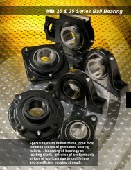
PREVENTIVE MAINTENANCETaper Lock SheavesTo install, insert bushing intosheaves. Match holes (not threads)and slip the entire unit onto shaft.Put screws into holes that arethreaded into the sheave only. Alignsheaves and tighten the screws. Asthe bushing is wedged inward, itcontacts and grips the shaft.10
HOW TO INSTALL SYNCHRONOUS BELTSDRIVE SHUTDOWN & THOROUGH INSPECTIONFollow these steps to install synchronous belt drive systems:1. After power has been locked out and tagged,loosen motor mounting bolts. Move motor until beltis slack and can be removed without prying. Neverpry off a belt!2. Remove old belt and check it for unusual wear.Excessive wear may indicate problems with thedrive design or maintenance program. Refer topages 26-33 for visual aids.3. Select correct replacement belt. Do not crimpbelts during handling or installation.4. Sprockets may be cleaned by wiping with a ragslightly dampened with a light, non-volatile solvent.Soaking or brushing the solvent on the belt is notadvisable. Obviously, sanding or scraping the beltor sprocket with a sharp object to remove greaseor debris is not recommended. <strong>Belt</strong>s must be drybefore using on a drive.5. Inspect sprockets for unusual or excessive wear.Check alignment. Proper alignment is very criticalwith synchronous belt drives. Check other drivecomponents such as bearings and shafts for alignment,lubrication, wear, etc.6. Install new belt over sprockets. Do not pry or useforce.7. Take up center distance on drive until proper tensionis obtained on the tension tester. Rotate driveby hand for a few revolutions and re-check tensionand alignment.9. Secure motor mounting bolts to correct torque. Besure all drive components are secure since anychange in drive centers during operation will resultin poor belt performance.10. Although belts will not require further tensioning,we recommend starting up the drive and observingperformance. Look and listen for unusual noiseor vibration. It's a good idea to shut down themachine and check bearings and motor. If theyfeel hot, belt tension may be too tight or bearingsmay be misaligned or not lubricated correctly.11
BELT IDENTIFICATIONDRIVE SHUTDOWN & THOROUGH INSPECTIONWhen preventive maintenance inspections indicate thatbelts need replacing, it’s important that you install thecorrect belts.<strong>Co</strong>nsequently, it is important that you be able to identifythe various types and sizes of belts available, and thenquickly be able to specify the correct replacement.The information on the following pages will help youbecome familiar with the belt types used in the industry.You’ll also discover that <strong>Gates</strong> makes a belt to fit nearlyany application you can name.V-<strong>Belt</strong>sSuper HC ® V-<strong>Belt</strong>sHi-Power ® II V-<strong>Belt</strong>sDubl V-<strong>Belt</strong>sTri-Power ® V-<strong>Belt</strong>sAA BB CCMetric Power V-<strong>Belt</strong>sDDSPZ/XPZSPA/XPASPB/XPBSPC/XPC12
Multi-Speed <strong>Belt</strong>sTop Width-Sheave AngleBELT IDENTIFICATIONTruflex ® (Light Duty) V-<strong>Belt</strong>sPoweRated ® V-<strong>Belt</strong>sPowerBand ® – Hi-Power II andSuper HC ®Micro-V ® <strong>Belt</strong>sStandard Polyflex ®Polyflex ® JB ®13
BELT IDENTIFICATIONDRIVE SHUTDOWN & THOROUGH INSPECTIONSynchronous <strong>Belt</strong>sAll synchronous belts are identified in a similar manner,in either English or metric units. <strong>Belt</strong>s are measured by:1. Pitch: Distance in inches or millimeters betweentwo adjacent tooth centers as measured on thebelt pitch line.2. Pitch Length: Total length (circumference) in inchesor millimeters as measured along the pitch line. It isequal to the pitch multiplied by the number of teeth inthe belt.3. Width: Denoted in inches or millimeters.Poly Chain ® GT ® 2 PowerGrip HTD ®PowerGrip GT2PowerGrip ® TimingPowerGrip GTTwin Power ® TimingTwin Power ® — PowerGrip GT & GT214
BELT TYPESNarrow Section V-<strong>Belt</strong>sThese high capacity belts are used to substantiallyreduce drive costs and decrease space requirements.This V-belt handles the complete range of drive horsepowerrecommended with three narrow cross sectionsinstead of the five regular cross sections needed forclassical heavy-duty belts. Specified by 3V, 5V or 8Vcross sections. Specify <strong>Gates</strong> Super HC ® V-<strong>Belt</strong>s.Classical Section V-<strong>Belt</strong>sThese are the original belts used in heavy duty applications.They are specified by cross section and standardlength. The size is designated as A, B, C, D or E. Theeasiest way to select a replacement is by finding thebelt number on the worn belt. If not legible, measurethe belts outside circumference with a flexible tape,preferably while it’s still on the drive.Then, order the <strong>Gates</strong> Hi-Power ll V-<strong>Belt</strong> which has thenext shorter standard length. For example: For an “A”section belt with a 28.0” O.C., order an A26 replacementbelt.Banded and Bandless <strong>Belt</strong>sBanded belts, also called wrapped or covered belts,have a fabric cover. Un-notched and generally withconcave sidewalls, they have rounded bottom cornersand arched tops.Bandless belts have no fabric cover They have straight,cut-edge sidewalls and special molded notches. Thesenotches reduce bending stress during operation whichallow them to run smaller diameter sheaves than cancomparable non-notched banded belts.<strong>Gates</strong> offers these two types in both the classical andnarrow sections. In the classical section, <strong>Gates</strong>Tri-Power ® molded notch is available in AX, BX and CXcross sections. Its length is specified by the same standardbelt number as other classical section belts.<strong>Gates</strong> also offers Super HC Molded Notch V-<strong>Belt</strong>s in3VX and 5VX sizes.In both cases, an “X” is used in the belt number to designatea molded notch construction. For example: AnAX26 is a bandless, molded notch classical sectionbelt. A 5VX1400 is a narrow section, bandless, moldednotch belt with a 140” O.C.Note: The revolutionary <strong>Gates</strong> Vextra construction isused in the notched belts.15
BELT TYPESLight Duty <strong>Belt</strong>sThese are used on light duty fractional horsepowerdrives and are designed for use with backside idlers.<strong>Gates</strong> Truflex ® and PoweRated ® V-<strong>Belt</strong>s are offered inthis category and are specified by cross section andoutside circumference. Truflex is recommended for thelower lighter duty range. PoweRated ® , a special beltdesigned for clutching, heavier shock-load and backsideidler drives, is recognized by its green color.Reinforced with an aramid fiber tensile (pound forpound stronger than steel). PoweRated can interchangewith Truflex, but Truflex cannot interchangewith PoweRated.Synchronous <strong>Belt</strong>sThese belts are also known as timing or positive drivebelts and are used where driveN shaft speeds must besynchronized to the rotation of the driveR shafts. Theycan also be used to eliminate noise and maintenanceproblems caused by chain drives.Synchronous belts, such as <strong>Gates</strong> Poly Chain ® GT ® 2,can be used in high horsepower drives... drives wherespace is severely limited... and where there is limitedtake up.Synchronous drives are extremely efficient... as muchas 98% with properly maintained Poly Chain GT2 orPowerGrip GT2 Systems. By contrast, chain drives arein the 91-98% efficiency range, while V-<strong>Belt</strong>s average inthe 93-98% range.Distinctive tooth profiles (shapes) identify synchronousbelts. Various sizes and constructions are available tomeet a wide range of applications. The three importantdimensions of a synchronous belt are pitch, width andpitch length. Tooth profiles must also be identified.<strong>Belt</strong> Pitch - Distance (mm) between two adjacent toothcenters as measured on the belt’s pitch line.<strong>Belt</strong> Pitch Length - Circumference (mm) as measuredalong the pitch line.Width - Top width (mm).Tooth Profile - See page 14 for the easiest way toidentify this.Synchronous belts run on sprockets, which are specifiedby the following:Pitch - Distance between groove centers, measured onthe sprocket pitch circle. The pitch circle coincides withthe pitch line of the mating belt.Number of Sprocket GroovesWidth - Face width.Note: The sprocket’s pitch diameter is always greaterthan its outside diameter.Note: PowerGrip GT2 belts must be used withPowerGrip GT2 sprockets for new designsNote: 8 and 14 mm pitch PowerGrip GT2 belts can beused as replacement belts at the next smaller width forthe following: HTD, Rpp, Rpp+Plus, HTB, HPT, HT100,HT150, ETH, HPR, HPPD, EHT or HTT.Example: 14mm-170mm width – substitute a PowerGripGT2-14mm-115 without any performance loss. Refer topage 22 for crossover information.Note: The 8mm and 14mm PowerGrip GT belts can beused in the PowerGrip GT2, HTD, Rpp, Rpp+Plus, HPT,HPPD and HT sprockets. Refer to page 22 forcrossover information.Note: PowerGrip GT belts can be used as a substitutefor HTD, Rpp, Rpp+Plus, HTB, HPT, HPPD, HT100,HT150, EHT or HPR without a performance loss. Referto page 22 for crossover information.16
BELT TYPESDRIVE SHUTDOWN & THOROUGH INSPECTIONPolyflex ® JB ® <strong>Belt</strong>Here is a unique belt with a distinctive 60° belt angleand ribbed top specifically designed for long life insmall diameter sheave drives. Polyflex JB is ideal forcompact drives, drives with high speed ratios, anddrives requiring especially smooth operation.The “JB” refers to the belt’s configuration. Two or threebelts joined together to provide extra stability andimproved performance. This joined belt style should beused instead of matched single belts whenever possible.You’ll find Polyflex JB <strong>Belt</strong>s in these applications:• Milling, grinding or drilling machines• Lathes• Machine spindle drives• Centrifuges• Blowers• High speed compressorsPolyflex JB <strong>Belt</strong>s are specified byTop Width and Effective LengthMulti-Speed <strong>Belt</strong>s(Variable Speed <strong>Drive</strong>s)Multi-Speed belts have a distinct shape. Multi-Speedbelt top widths are usually greater than their thicknesses.This permits a greater range of speed ratios thanstandard belts. Usually cogged or notched on theunderside, Multi-Speed belts are specified for equipmentwhich require changes in driveN speed duringoperation.Multi-Speed belts are specified by Top Width, OutsideCircumference, and the required Groove Angle. Thegroove angle can be measured from the drive pulleys.Micro-V ® or V-Ribbed <strong>Belt</strong><strong>Gates</strong> Micro-V <strong>Belt</strong>s outperform other V-ribbed beltsbecause the are truncated (shorter). This shorter profilegives the new Micro-V <strong>Belt</strong>s increased flexibility,reduced heat buildup and allows them to operate atextra high speeds on smaller diameter sheaves.Two more advantages of the truncated are: (1) the beltdoes not bottom in the sheave, and (2) the belt can bettertolerate debris in the sheave groove. They are extremelysmooth running and highly resistant to oil, heat and otheradverse conditions.Three cross sections are available for industrial applications:J, L and M.17
BELT STYLESSpliced <strong>Belt</strong>ingUsed on drives with little or no take-up, or as an emergencybelt replacement.<strong>Belt</strong>ing is sold on reels in standard V-<strong>Belt</strong> cross sections.Ends are spliced with fasteners that require specialassembly tools. Always use the correct fastenerswith the correct belt type and cross section.Nu-T-Link*, a new, high performance, spliced belt, isalso available for use as emergency belting, and fordrives where conditions are detrimental to rubber belts.PowerBand ® <strong>Belt</strong>sPowerBand belts were developed by <strong>Gates</strong> for drivessubjected to pulsating loads, shock loads or extremevibrations where single belts could flip over on the pulleys.A high-strength tie band permanently joins two ormore belts to provide lateral rigidity. This keeps the beltsrunning in a straight line in the pulley grooves.PowerBand construction is offered with <strong>Gates</strong>Hi-Power ® II, Super HC ® and Super HC MoldedNotch <strong>Belt</strong>s.The <strong>Gates</strong>Predator V-<strong>Belt</strong> isa multi layeredPowerBand ® constructionthat addsstrength, durability, shear and tear resistance andlateral rigidity to handle the toughest shock-loadedapplications. It is available in Super HC andHi- Power II profiles.Predator V-<strong>Belt</strong>s primary features:• Aramid tensile cords for extraordinary strength, durabilityand virtually zero stretch.• Chloroprene rubber compounds for superb oil andheat resistance.• Specially-treated cover withstands slip and shearforces at peak loads without generating excessiveheat. It also fends off penetration by foreignmaterials.• <strong>Gates</strong> curves that compensate for effects that occurwhen belts bend around a sheave for uniform loadingand maximum life.• Precision-matched to maximize power absorption andbelt life.*Registered Trademark of Fenner-Manheim.18
BELT STYLESDRIVE SHUTDOWN & THOROUGH INSPECTIONDubl-V <strong>Belt</strong>A special version of <strong>Gates</strong> Hi-Power ® II for serpentinedrives where power is transmitted by both the top andbottom of the belt. Dubl-V belts are specified by A, B,or C cross sections, and by Effective Length.Round Endless <strong>Belt</strong>sRecommended for replacing leather belting on serpentineor quarter-turn drives. They are specified byDiameter and Inside Length.If your current drive has leather or round endless belting,you should consider a new drive design. V-beltdrives offer many advantages in performance, even onserpentine or quarter-turn drives.Power Cable ®Recommended for the toughest shock load applications,especially on drives that can’t be shut down forretensioning after initial belt run-in. Reinforced with anaramid fiber tensile (pound for pound stronger thansteel), Power Cable belts last longer and costs lessthan steel cable belts.19
BELT STYLESFlat <strong>Belt</strong>s<strong>Gates</strong> Speed- Flex ® <strong>Belt</strong>s, are designed for high speedapplications such as drill presses, lathes, grinders andother woodworking equipment. <strong>Gates</strong> Powercord ® <strong>Belt</strong>sare designed for general purpose, lower speed applications.Flat belts are specified by belt Width andrequired Inside Diameter.Static <strong>Co</strong>nductive <strong>Belt</strong>sRubber Manufacturers’ Association (RMA) has publishedBulletin IP 3-3 for static conductivity. Static conductivitytesting involves passing an electrical currentof specified voltage through a section of belt and thenmeasuring the belt’s resistance to conduct the current.A resistance reading of six (6) megohms or more constitutesa test failure. Past testing has demonstratedthat six (6) megohms or less is sufficient to preventmeasurable static voltage buildup, thus preventing astatic discharge.A static discharge can interfere with radios and electronicinstruments or controls used in your facility. It canalso cause bearing pitting if the discharge occursthrough the bearing. Static discharge can pose a hazardon drives that operate within potentially explosiveenvironments.V-belts are generally manufactured in accordancewith the RMA bulletin, but you must check the staticconductivity with the manufacturer.PowerGrip ® and Poly Chain ® belts do not meet thestatic conductivity requirements specified in RMABulletin IP-3-3/1995.The RMA bulletin applies to new, clean belts. <strong>Belt</strong>scan collect debris or become worn and damagedand prevent a circuit, thus negating the static conductivityof the belt.When a belt is used in a hazardous environment, werecommend that additional protection be taken toassure no accidental static spark discharges. Theentire system must be properly grounded. A staticconductivebrush or similar device is recommendedto bleed off any static buildup on the belt that mightoccur.20
BELT DRIVE PERFORMANCE & TROUBLESHOOTINGDRIVE SHUTDOWN & THOROUGH INSPECTIONTo provide proper maintenance, you must understandthe nature of the belt drives in your plant. You know theexpected belt service life on each drive, and you areaware of the capabilities and limitations of this equipment.On occasion, however, it is necessary to give somethought to belt service life, especially in these situations:• When belt service life is meeting expectations, butyou would like to reduce existing maintenancecosts and down time.• When belt service life is below the expected performancelevel and the situation must be improved.Upgrade <strong>Drive</strong> PerformanceA belt drive can sometimes be upgraded to improveperformance. The first step is to see if simple improvementscan be made at minimal costs. This involveschecking the drive design for adequate capacity.If further improvement is needed, the next step is toupgrade the drive to a higher performance belt system.Here are examples of minor changes that couldimprove performance.• Increase pulley diameters• Increase the number of belts, or use wider belt• Add vibration dampening to system• Improve guard ventilation to reduce operating temperature• Use at least the correct, minimum recommendedpulley diameters on inside and backside idlers• Use premium belts rather than general purposetypes• Replace pulleys when they are worn• Keep pulleys properly aligned• Place idler on span with lowest tension and asclose to drives as possible• Re-tension newly installed belts after a 4 - 24 hourrun-in period• Review proper belt installation and maintenanceprocedures21
BELT DRIVE PERFORMANCE & TROUBLESHOOTINGDRIVE SHUTDOWN & THOROUGH INSPECTIONThe <strong>Gates</strong> Rubber <strong>Co</strong>mpany is the recognized industryleader in product innovation and belt drive technology.New products and applications are continually madeavailable to <strong>Gates</strong> customers. Here are examples ofadvanced <strong>Gates</strong> belt innovations.Advanced <strong>Gates</strong> <strong>Belt</strong> Innovations• Poly Chain ® GT ® 2 positive drive (synchronous) belts• Power Grip ® GT2• Polyflex ® JB ® belts• Power Cable ® belts• PoweRated ® light-duty V-belts• Nu-T-Link* spliced belting• Super HC ® Molded Notch V-belts• Predator Powerband belts• Vextra technology*Registered Trademark of Fenner-Manheim.Your local <strong>Gates</strong> distributor or representative can workwith you to upgrade your existing drives and reduceyour maintenance and down time costs.Or, you may have a problem or excessive maintenancecosts with a non-belt drive, such as gear or chain.Again, your local <strong>Gates</strong> distributor or representativecan offer you excellent advice as to whether or not abelt drive could solve the problem and reduce yourmaintenance costs.Improving Poor <strong>Drive</strong> PerformanceIf your belt drive system is properly designed, installedand maintained, it will need very little attention.Occasionally, however, a drive can be accidentallydamaged or knocked out of adjustment.Changing operating requirements or environmentalconditions can also create problems.Design Performance Grouping – PowerGrip GTPowerGrip GT – 8 & 14mm <strong>Belt</strong>s can be used to replace other non-<strong>Gates</strong> curvilinear belts in the same width<strong>Co</strong>mpany Product Trade Name Nomenclature <strong>Belt</strong>-Pitch ProfileBando Synchro-Link – HT 1600-8M-20-H 8 & 14mm HTDDodge HT100 1600-8M-20-HT100 8 & 14mm HTDElectron EHT 1600-8M-20 8 & 14mm HTD<strong>Gates</strong> HTD 1600-8M-20 8 & 14mm HTDJason HTB 1600-8M-20 8 & 14mm HTDMBLHTT 1600-8M-20 8 & 14mm HTDOpti <strong>Belt</strong> HTD 1600-8M-20 8 & 14mm HTDBrowning HPT 1610-14M-40 14mm RPPDayco RPP 1610-14M-40 14mm RPPGoodyear HPPD 1610-14M-40 14mm RPPT.B. Woods RPP 1610-14M-40 14mm RPPThermoid Syncho-Curve Timiing 1610-14M-40 14mm RPPDesign Performance Grouping – PowerGrip GT2PowerGrip GT2 – 8 & 14mm <strong>Belt</strong>s can be used to replace other non-<strong>Gates</strong> curvilinear belts in the next smallest width<strong>Co</strong>mpany Product Trade Name Nomenclature <strong>Belt</strong>-Pitch ProfileBando Synchro-Link – HT 1600-8M-20-H 8 & 14mm HTDDodge HT100 1600-8M-20-HT100 8 & 14mm GTElectron EHT 1600-8M-20 8 & 14mm HTD<strong>Gates</strong> HTD 1600-8M-20 8 & 14mm HTDJason HTB 1600-8M-20 8 & 14mm HTDMBLHTT 1600-8M-20 8 & 14mm HTDOpti <strong>Belt</strong> HTD 1600-8M-20 8 & 14mm HTDBrowning HPT 1610-14M-40 14mm RPPDayco RPP 1610-14M-40 14mm RPPGoodyear HPPD 1610-14M-40 14mm RPPT.B. Woods RPP 1610-14M-40 14mm RPPThermoid Syncho-Curve Timing 1610-14M-40 14mm RPPDayco RPP Plus 1610-14M-40 14mm RPPDayco HPR 1610-14M-40 14mm RPPDodge HT150 1610-14M-40-HT-150 8 & 14mm GTT.B. Woods RPP Plus 1610-14M-40 14mm RPPT.B. Woods HPR 1610-14M-40 14mm RPP<strong>Co</strong>mpetitors Width PowerGrip GT2 – Width <strong>Co</strong>mpetitors Width PowerGrip GT2 – Width8mm – Pitch 8mm – Pitch 14mm - Pitch 14mm – Pitch20 20 40 4030 20 55 4050 30 85 5585 50 115 8522
TROUBLESHOOTING GUIDEDRIVE SHUTDOWN & THOROUGH INSPECTIONWhen troubleshooting a drive problem, your goal is toidentify the cause(s), then take appropriate correctiveaction. We have developed a worksheet to help youwith this process. Here is how to use it.1. Describe your drive problem as accurately as possible.Use Step 1 as a guide. Use this step as aguide in the troubleshotting process.2. Go through the list of “<strong>Drive</strong> Symptoms”. Checkthose symptoms you observe and record them, aswell as your observations of anything unusualabout the drive.3. Go through the “Probable Cause and ActionSummary Table”. List the probable cause(s) andcorrective action. Also, review your list of observations.4. Note your completed list of probable cause(s) andcorrective action. Also, review your list of observations.5. Determine if these two lists spotlight a particularproblem source.What to Do When All Else FailsWe’ve covered all of the most common belt drive problemsyou might encounter. However, if the problem stillexists after all of your troubleshooting efforts have beenexhausted, contact your <strong>Gates</strong> distributor. If he cannotsolve the problem for you, he’ll put you in touch with aqualified <strong>Gates</strong> representative.23
TROUBLESHOOTING GUIDEDRIVE SHUTDOWN & THOROUGH INSPECTIONStep 1Describe the problem• What is wrong?• When did it happen?• How often does it happen?• What is the drive application?• Have the machine operations or output changed?• What kind of belt(s) are you using?• What are your expectations for belt performance inthis application?Step 2Identify symptoms and recordobservations of anything unusual.<strong>Drive</strong> SymptomsCheck List(Check those you observe)• Banded (Joined) <strong>Belt</strong> Problems■ Tie-band separation■ Top of tie-band frayed, worn or damaged■ Band comes off drive■ One or more ribs run outside of pulley• V-belt Turns Over or Jumpsoff Sheave■ Single belt■ One or more belts in a set■ Joined or banded belts• <strong>Belt</strong> Stretches Beyond Take-Up■ Single belt■ Multiple belts stretch unequally■ All belts stretch equally• Premature <strong>Belt</strong> Failure■ Broken belt(s)■ <strong>Belt</strong>(s) fail to carry load (slip). No visible reason■ Edge cord failure■ <strong>Belt</strong> delamination or undercord separation• Severe or Abnormal <strong>Belt</strong> Wear■ Wear on belt top surface■ Wear on top corners of belt■ Wear on belt sidewall■ Wear on belt bottom corners■ Wear on bottom surface of belt■ Undercord cracking■ Burn or hardening on bottom or sidewall■ <strong>Belt</strong> surface flaking, sticky or swollen■ <strong>Belt</strong> stretch■ Extensive hardening of belt exterior24
TROUBLESHOOTING GUIDETROUBLESHOOTING GUIDEAll V-<strong>Belt</strong> <strong>Drive</strong>s• <strong>Belt</strong> Noise■ Squeal or “chirp”■ Slapping noise■ Rubbing sound■ Grinding■ Unusually loud drive• Unusual Vibration■ <strong>Belt</strong>s flopping■ Excessive vibration in drive systemAll Synchronous <strong>Belt</strong> <strong>Drive</strong>s• <strong>Belt</strong> Problems■ Unusual noise■ Tension loss■ Excessive belt edge wear■ Tensile break■ Cracking■ Premature tooth wear■ Tooth shear■ <strong>Belt</strong> ratcheting■ Land area worn• Problem With Pulleys■ Broken or damaged■ Severe, rapid groove wear• Problems With <strong>Drive</strong><strong>Co</strong>mponents■ Bent or broken shafts■ Damaged guard• Hot Bearings• Performance Problems■ Incorrect driveN speeds• Sprocket Problems■ Flange failure■ Unusual wear• Problems With Take Up■ Make sure you are using <strong>Gates</strong> belts■ Not all belts are same• Performance Problems■ <strong>Belt</strong> tracking problems■ Excessive temperature: bearings, housings,shafts, etc.■ Shafts out of sync■ Vibration25
PROBLEM/SOLUTION SUMMARY TABLEDRIVE SHUTDOWN & THOROUGH INSPECTIONPremature <strong>Belt</strong> FailureSymptoms• Broken belt(s)Probable Cause1. Under-designed drive2. <strong>Belt</strong> rolled or pried onto sheave3. Object falling into drive4. Severe shock load<strong>Co</strong>rrective Action1. Redesign, using <strong>Gates</strong> manual.2. Use drive take-up wheninstalling.3. Provide adequate guard or driveprotection.4. Redesign to accommodateshock load.• <strong>Belt</strong>s fail to carry load, no visiblereason1. Underdesigned drive2. Damaged tensile member3. Worn sheave grooves4. Center distance movement1. Redesign, using <strong>Gates</strong> manual.2. Follow correct installation procedure.3. Check for groove wear; replaceas needed.4. Check drive for center distancemovement during operation.• Edge cord failure1. Pulley misalignment2. Damaged tensile member1. Check alignment and correct.2. Follow correct installationprocedure.• <strong>Belt</strong> de-lamination or undercordseparation1. Too small sheaves2. Use of too small backside idler1. Check drive design, replace withlarger sheaves.2. Increase backside idler toacceptable diameter.26
PROBLEM/SOLUTION SUMMARY TABLEDRIVE SHUTDOWN & THOROUGH INSPECTIONSevere or Abnormal V-<strong>Belt</strong> WearSymptoms• Wear on top surface of beltProbable Cause1. Rubbing against guard2. Idler malfunction<strong>Co</strong>rrective Action1. Replace or repair guard.2. Replace idler.• Wear on top corner of belt1. <strong>Belt</strong>-to-sheave fit incorrect (belttoo small for groove)1. Use correct belt-to-sheavecombination.• Wear on belt sidewalls1. <strong>Belt</strong> slip2. Misalignment3. Worn sheaves4. Incorrect belt1. Retention until slipping stops.2. Realign sheaves.3. Replace sheaves.4. Replace with correct belt size.• Wear on bottom corner of belt1. <strong>Belt</strong>-to-sheave fit incorrect2. Worn sheaves1. Use correct belt-to-sheave combination.2. Replace sheaves.• Wear on bottom surface of belt1. <strong>Belt</strong> bottoming on sheave groove2. Worn sheaves3. Debris in sheaves1. Use correct belt/sheave match.2. Replace sheaves.3. Clean sheaves.• Undercord cracking1. Sheave diameter too small2. <strong>Belt</strong> slip3. Backside idler too small4. Improper storage1. Use larger diameter sheaves.2. Retention.3. Use larger diameter backsideidler.4. Don’t coil belt too tightly, kink orbend.Avoid heat and direct sunlight.27
PROBLEM/SOLUTION SUMMARY TABLEDRIVE SHUTDOWN & THOROUGH INSPECTIONSevere or Abnormal V-<strong>Belt</strong> Wear–cont.Symptoms• Undercord or sidewall burn orhardeningProbable Cause1. <strong>Belt</strong> slipping2. Worn sheaves3. Underdesigned drive4. Shaft movement<strong>Co</strong>rrective Action1. Retension until slipping stops.2. Replace sheaves.3. Refer to <strong>Gates</strong> drive manual.4. Check for center distancechanges.• <strong>Belt</strong> surface hard or stiff1. Hot drive environment1. Improve ventilation to drive.• <strong>Belt</strong> surface flaking, sticky orswollen1. Oil or chemical contamination1. Do not use belt dressing.Eliminate sources of oil, greaseor chemical contamination.V-<strong>Belt</strong>s Turn Over or <strong>Co</strong>me Off <strong>Drive</strong>Symptoms• Involves single or multiple beltsProbable Cause1. Shock loading or vibration2. Foreign material in grooves3. Misaligned sheaves4. Worn sheave grooves5. Damaged tensile member6. Incorrectly placed flat idler7. Mismatched belt set8. Poor drive design<strong>Co</strong>rrective Action1. Check drive design. Use <strong>Gates</strong>PowerBand ® belts or PowerCable ® belts.2. Shield grooves and drive.3. Realign the sheaves.4. Replace sheaves.5. Use correct installation and beltstorage procedure.6. Carefully align flat idler on slackside of drive as close as possibleto driveR sheaves.7. Replace with new set of matchedbelts.Do not mix old and newbelts.8. Check for center distance stabilityand vibration dampening.28
PROBLEM/SOLUTION SUMMARY TABLEDRIVE SHUTDOWN & THOROUGH INSPECTION<strong>Belt</strong> Stretches Beyond Available Take-UpSymptoms• Multiple belts stretch unequally• Single belt, or where all beltsstretch evenly<strong>Belt</strong> NoiseSymptoms• <strong>Belt</strong> squeals or chirps• Slapping Sound• Rubbing sound• Grinding sound• Unusually loud driveUnusual VibrationSymptoms• <strong>Belt</strong>s flopping• Unusual or excessive vibrationProbable Cause1. Misaligned drive2. Debris in sheaves3. Broken tensile member or corddamaged4. Mismatched belt set1. Insufficient take-up allowance2. Grossly overloaded or underdesigned drive3. Broken tensile membersProbable Cause1. <strong>Belt</strong> slip2. <strong>Co</strong>ntamination1. Loose belts2. Mismatched set3. Misalignment1. Guard interference1. Damaged bearings1. Incorrect belt2. Incorrect Tension3. Worn sheaves4. Debris in sheavesProbable Cause1. Loose belts (under tensioned)2. Mismatched belts3. Pulley misalignment1. Incorrect belt2. Poor machine or equipmentdesign3. Pulley out of round4. Loose drive components29<strong>Co</strong>rrective Action1. Realign and retension drive.2. Clean sheaves.3. Replace all belts, install properly.4. Install matched belt set.1. Check take-up. Use allowancespecified in <strong>Gates</strong> design manuals.2. Redesign drive.3. Replace belt, install properly.<strong>Co</strong>rrective Action1. Retension.2. Clean belts and sheaves.1. Retension.2. Install matched belt set.3. Realign pulleys so all belts shareload equally.1. Repair, replace or redesign guard.1. Replace, align & lubricate.1. Use correct belt size. Use correctbelt tooth profile for sprocketson synchronous drive.2. Check tension and adjust3. Replace sheaves4. Clean sheaves, improve shielding,remove rust, paint, orremove dirt from grooves.<strong>Co</strong>rrective Action1. Retension.2. Install new matched set.3. Align pulley1. Use correct belt cross section inpulley. Use correct tooth profileand pitch in sprocket.2. Check structure and brackets foradequate strength.3. Replace with non-defective pulley.4. Check machine components andguards, motor mounts, motorpads, bushings, brackets andframework for stability adequatedesign strength, proper maintenanceand proper installation.
PROBLEM/SOLUTION SUMMARY TABLEDRIVE SHUTDOWN & THOROUGH INSPECTIONProblems With SheavesSymptoms• Broken or damaged sheave• Severe Groove WearProbable Cause1. Incorrect sheave installation2. Foreign objects falling into drive3. Excessive rim speeds4. Incorrect belt installation1. Excessive belt tension2. Sand, debris or contamination3. Wrong belt<strong>Co</strong>rrective Action1. Do not tighten bushing bolts beyondrecommended torque values.2. Use adequate drive guard.3. Keep pulley rim speeds belowmaximum recommended value.4. Do not pry belts onto pulleys.1. Retension, check drive design.2. Clean and shield drive as well aspossible.3. Make sure belt and sheave combinationis correct.Problem With Other <strong>Drive</strong> <strong>Co</strong>mponentsSymptoms• Bent or broken shaftHot BearingsSymptoms• <strong>Drive</strong> needs overtensioning• Sheaves too small• Poor bearing condition• Sheaves too far out on shaft• <strong>Belt</strong> slippagePerformance ProblemsSymptoms• Incorrect driveN speedProbable Cause1. Extreme belt overtension2. Overdesigned drive*3. Accidental damage4. Machine design error5. Accidental damage to guard orpoor guard design6. Pulley mounted too far awayfrom outboard bearingProbable Cause1. Worn grooves - belts bottomingand won’t transmit power untilovertensioned*2. Improper tension1. Motor manufacturer’s sheavediameter recommendation notfollowed1. Bearing underdesigned2. Bearing not properly maintained1. Error or obstruction problem1. <strong>Drive</strong> undertensionedProbable Cause1. Design error2. <strong>Belt</strong> slip<strong>Co</strong>rrective Action1. Retension2. Check drive design, may need touse smaller or fewer belts.3. Redesign drive guard.4. Check machine design.5. Repair, redesign for durability.6. Move pulley closer to bearing.<strong>Co</strong>rrective Action1. Replace sheaves. Tension driveproperly.2. Retension.1. Redesign using drive manual.1. Check bearing design.2. Align and lubricate bearing.1. Place sheaves as close as possibleto bearings. Remove obstructions1. Retension.<strong>Co</strong>rrective Action1. Use correct driveR/driveN sheavesize for desired speed ratio.2. Retension driveR.Use synchronous belt.* Using too many belts, or belts that are too large, can severely stress motor or driveN shafts. This can happen when load requirements arereduced on a drive, but the belts are not redesigned accordingly. This can also happen when a drive is greatly overdesigned. Forces createdfrom belt tensioning are too great for the shafts.30
PROBLEM/SOLUTION SUMMARY TABLEDRIVE SHUTDOWN & THOROUGH INSPECTIONProblems With Banded (Joined) <strong>Belt</strong>sSymptoms• Tie band separationProbable Cause1. Worn sheaves2. Improper groove spacing<strong>Co</strong>rrective Action1. Replace sheaves.2. Use standard groove sheaves.• Top of tie band frayed or worn1. Interference with guard2. Backside idler malfunction ordamaged1. Check guard.2. Replace or repair backside idler• PowerBand ® belt comes off driverepeatedly• One or more “ribs” runs out ofpulley1. Debris in sheaves2. Misalignment1. Misalignment2. Undertensioned1. Clean grooves. Use single beltsto prevent debris from beingtrapped in grooves.2. Realign drive.1. Realign drive.2. Retension.Problems With Synchronous <strong>Belt</strong>sSymptoms• Unusual noiseProbable Cause1. Misaligned drive2. Too low or high tension3. Backside idler4. Worn sprocket5. Bent guide flange6. <strong>Belt</strong> speed too high7. Incorrect belt profile for sprocket(i.e. HTD, GT ® , etc.)8. Subminimal diameter9. Excess load<strong>Co</strong>rrective Action1. <strong>Co</strong>rrect alignment.2. Adjust to recommended value3. Use inside idler.4. Replace.5. Replace.6. Redesign drive.7. Use proper belt/sprocket combination.8. Redesign drive using largerdiameters.9. Redesign drive for increasedcapacity.31
PROBLEM/SOLUTION SUMMARY TABLEDRIVE SHUTDOWN & THOROUGH INSPECTIONTension LossExcessive <strong>Belt</strong> Edge WearTensile Break1. Weak support structure2. Excessive sprocket wear3. Fixed (non-adjustable) centers4. Excessive debris5. Excessive load6. Subminimal diameter7. <strong>Belt</strong>, sprocket or shafts runningtoo hot8. Unusual belt degradation1. Damage due to handling2. Flange damage3. <strong>Belt</strong> too wide4. <strong>Belt</strong> tension too low5. Rough flange surface finish6. Improper tracking7. <strong>Belt</strong> hitting drive guard orbracketry8. Misalignment1. Excessive shock load2. Subminimal diameter3. Improper belt handling and storageprior to installation (crimping)4. Debris or foreign object in drive5. Extreme sprocket run-out1. Reinforce structure.2. Use alternate sprocket material.3. Use inside idler for belt adjustment.4. Remove debris, check guard.5. Redesign drive for increasedcapacity.6. Redesign drive using largerdiameters.7. Check for conductive heat transferfrom prime mover.8. Reduce ambient drive temperatureto 185°F maximum.1. Follow proper handling instructions.2. Repair flange or replace sprocket.3. Use proper width sprocket.4. Adjust tension to recommendedvalue.5. Replace or repair flange (to eliminateabrasive surface).6. <strong>Co</strong>rrect alignment.7. Remove obstruction or useinside idler.8. Realign drive1. Redesign drive for increasedcapacity.2. Redesign drive using largerdiameters.3. Follow proper storage and handlingprocedures.4. Remove objects and checkguard.5. Replace sprocket.<strong>Belt</strong> CrackingPremature Tooth Wear1. Subminimal diameter2. Backside idler3. Extreme low temperature at start-up.4. Extended exposure to harshchemicals5. <strong>Co</strong>cked bushing/sprocketassembly1. Too low or high belt tension2. <strong>Belt</strong> running partly off unflangedsprocket3. Misaligned drive4. Incorrect belt profile for sprocket(i.e. HTD, GT ® , etc)5. Worn sprocket6. Rough sprocket teeth1. Redesign drive using largerdiameter.2. Use inside idler or increasediameter of backside idler.3. Pre-heat drive environment.4. Protect drive.5. Install bushing per instructions.1. Adjust to recommended value.2. <strong>Co</strong>rrect alignment.3. <strong>Co</strong>rrect alignment.4. Use proper belt/sprocket combination.5. Replace.6. Replace sprocket32
PROBLEM/SOLUTION SUMMARY TABLEDRIVE SHUTDOWN & THOROUGH INSPECTIONPremature Tooth Wear–cont.Tooth Shear7. Damaged sprocket8. Sprocket not to dimensionalspecification9. <strong>Belt</strong> hitting drive bracketry orother structure10.Excessive load11.Insufficient hardness of sprocketmaterial12.Excessive debris13.<strong>Co</strong>cked bushing/sprocketassembly1. Excessive shock loads2. Less than 6 teeth-in-mesh3. Extreme sprocket run-out4. Worn sprocket5. Backside idler6. Incorrect belt profile for thesprocket (i.e. HTD, GT ® , etc.)7. Misaligned drive8. <strong>Belt</strong> undertensioned7. Replace.8. Replace.9. Remove obstruction or use idler10.Redesign drive for increasedcapacity11.Use a more wear-resistantsprocket12.Remove debris, check guard.13.Install bushing per instructions.1. Redesign drive for increasedcapacity.2. Redesign drive.3. Replace sprocket.4. Replace.5. Use inside idler6. Use proper belt/sprocket combination.7. Realign.8. Adjust tension to recommendedvalue.Flange Failure 1. <strong>Belt</strong> forcing flange off 1. <strong>Co</strong>rrect alignment or properlysecure flange to sprocket.Unusual Sprocket Wear1. Sprocket has too little wearresistance (i.e. plastic, aluminum,soft metals)2. Misaligned drive3. Excessive debris4. Excessive load5. belt tension too low or high6. Incorrect belt profile (i.e. HTD,GT, etc.)1. Use alternate sprocket material.2. <strong>Co</strong>rrect alignment.3. Remove debris, check guard.4. Redesign drive for increasedcapacity.5. Adjust tension to recommendedvalue.6. Use proper belt/sprocket combination.<strong>Belt</strong> TrackingExcessive Temperature(<strong>Belt</strong>, Bearing, Housing,Shafts, etc.)Shafts Out of SyncVibration1. <strong>Belt</strong> running partly off unflangedsprocket2. Centers exceed 8 times smallsprocket diameter and bothsprockets are flanged.3. Excessive belt edge wear1. Misaligned drive2. Too low or high belt tension3. Incorrect belt profile (i.e. HTD,GT, etc.)1. Design error2. Incorrect belt1. Incorrect belt profile for thesprocket (i.e. HTD, GT, etc.)2. Too low or high belt tension3. Bushing or key loose1. <strong>Co</strong>rrect alignment.2. <strong>Co</strong>rrect parallel alignment to setbelt to track on both sprockets.3. <strong>Co</strong>rrect alignment.1. <strong>Co</strong>rrect alignment.2. Adjust tension to recommendedvalue.3. Use proper belt/sprocket combination.1. Use correct sprocket sizes.2. Use correct belt with correcttooth profile for grooves.1. Use proper belt/sprocket combination.2. Adjust tension to recommendedvalue.3. Check and reinstall per instructions.33
TROUBLESHOOTING TOOLSDRIVE SHUTDOWN & THOROUGH INSPECTIONYou are faced with a problem drive and must determinethe cause. The tools available to help you troubleshootrange from the surprisingly simple to complicated.Following is a list of tools you can use to effectivelydiagnose a problem. While <strong>Gates</strong> does not sell most ofthe items discussed in this section, unless noted, theitems are readily available from industrial instrumentationoutlets throughout the United States.Eyes, Ears, Nose & HandsWhen troubleshooting a belt drive problem, stand backand observe the drive while it is in operation and atrest. Do you smell warm rubber? Can you see anythingunusual about the way the belt travels around thedrive? Is the drive frame flexing under load? Do youhear chirping, squealing or grinding noises? Is there anaccumulation of fabric dust beneath the drive whichmight interfere with the belts?Squirt Bottle With Soapy WaterWhen a belt drive is excessively noisy, the belt is oftenincorrectly blamed. It is easy to eliminate the belt as theproblem by spraying it with soapy water while it is running.If the noise goes away, or decreases, then thebelt is part of the problem. If you still hear the samenoise, the problem is likely due to other drive components.Ball Of StringVariation in drive center distance, often caused byweak supporting structure, can cause problems fromvibration to short belt life. To determine if center distancevariation exists, turn off the drive and tightly tie apiece of string from the driveR to the driveN shaft.Startup the drive and note if the string stretches almost tothe point of breaking, or goes slack. If either is thecase, the problem could be center distance variation. Itis particularly important to observe the string right atdrive start up when the loads are highest. String canalso be used to check pulley alignment.<strong>Belt</strong> & Sheave Groove GaugesIf you suspect a belt-to-sheave groove mismatch,English and metric belt and sheave groove gauges canbe used to check dimensions. These also are handy foridentifying abelt cross sectionfor replacementsand forcheckingsheave groovesfor wear.These gaugesare availablefrom your beltsupplier Forprice information,contactyour <strong>Gates</strong>distributor.English Gauge:Form #13998Metric Gauge:Form #13998-MLong Straight EdgeWhile V-<strong>Belt</strong>s can be somewhat forgiving of misalignment,this condition can still affect V-<strong>Belt</strong> performance.Even slight misalignment can cause major problems ona synchronous drive.Use a long straight edge, made ofwood, metal or any rigid material, to quickly checkdrive alignment. Simply lay the straight edge across thepulley faces and note the points of contact (or lack ofcontact).Design Flex ® and Design View ®<strong>Gates</strong> design suite of engineering programs includeinteractive support software and a user friendly interfacefor rapid data retrieval and smooth design work.NOTE: In some cases redesign of the drive is necessary.<strong>Gates</strong> <strong>Drive</strong> Design software provides a quick,accurate and flexible method of correctly redesigningproblem drives.34
TROUBLESHOOTING TOOLSACEFBDG<strong>Belt</strong> Tension TestersImproper belt tension, either toohigh or too low, can cause beltdrive problems. An “experienced”thumb may be okay for ordinarydrives, but for critical drives,<strong>Gates</strong> recommends using atension gauge. Proper tension andinstallation can extend belt life andreduce costly downtime.Several types of tension gaugesare available.A. “Double Barrel”Tension Tester(Product No. 7401-0075)Maximum deflection force: 66lbs. For use with all multipleV-<strong>Belt</strong> and large synchronousdrives, including PowerBand ®and Poly Chain ® GT ® belt drives.*A 5-Barrel Tension Tester is alsoavailable. <strong>Co</strong>ntact your <strong>Gates</strong>representative for details.B. Tension Tester(Pencil Type)(Product No. 7401-0076)Maximum deflection force: 30lbs. For use with all small V-<strong>Belt</strong>and synchronous drives, includingPowerBand and Poly ChainGT belt drives.The pencil type tension testersare recommended for use with:• Super HC V-<strong>Belt</strong>s• Hi Power II V-<strong>Belt</strong>s• PowerBand <strong>Belt</strong>s• Poly Chain GT2 <strong>Belt</strong>s• PowerGrip GT2 <strong>Belt</strong>sC. Krikit Gauge(Product No. 7401-0071)For use with:•Automotive V-<strong>Belt</strong>sD. Sonic Tension MeterNow!- More compact and easy to use.For extremely accurate belt tensionmeasuring, the <strong>Gates</strong> SonicTension Meter is an electronicdevice that measures the naturalfrequency of a free stationary beltspan and instantly computes thestatic belt tension based upon thebelt span length, belt width andbelt type.Features:• Uses sound waves instead offorce/deflection.• Results are repeatable with anyoperator.• Portable, lightweight and easy to use.• Fast. Calculates tension in seconds.• Can be used in almost any environment.• Model 505C runs on two AAAbatteries.• Model 305FD runs on four AAAbatteries.• Model 305FD connects to a computerfor data downloading.35D. Model 505C - Product No.7420-0201E. Model 305FD - ProductNo. 7420-0203Accessories:F. Flexible Sensor -Product No. 7420-0204(Optional with 505C)G. Optional Inductive Sensor- Product No. 7420-0212Both Models:For use with these belts:All synchronous beltsMicro-V® beltsPolyflex® belts
TROUBLESHOOTING TOOLSTROUBLESHOOTING TOOLSTension GaugeImproper belt tension,either too high or too low,can cause belt driveproblems. Several typesof tension gauges areavailable; see page 35.An inexpensive penciltype is adequate formost situations. Seeyour local <strong>Gates</strong> distributorfor price andavailability.Vibrotach TachometerThis tool can be used to isolate theforcing frequency behind vibrationproblems. It is a small, hand-helddevice which can be butted upagainst the vibrating equipment. Athin metal reed protrudes from theend, the length of which can bevaried. As you vary the length, thereed will vibrate wildly at somepoint. The tachometer scale thengives you the forcing rpm or frequency.Once the system frequenciesare identified, it is easy totrace and correct the source of theproblem.Available from:Martin Engineering <strong>Co</strong>.U.S. route 34Neponset, IL 613451-800-544-2947Dial IndicatorImproperly mounted sheaves or outof-roundpulleys are sometimes theroot of vibration or more severeproblems. This device can be usedto measure side-to-side sheave wobbleor diameter variation by holdingit up to the sheave sidewall or top ofthe belt inside the pulley groove,respectively. IMPORTANT: Alwaysturn off the machine before using thedial indicator. Rotate the drive byhand to make your measurements.Clamp-On AmmeterIf belts are failing prematurely, it’spossible the driveN load wasunderestimated when the drive wasdesigned. Use the ammeter tocheck the actual load being deliveredby an electric motor. Theclamp-on style allows you to do thissafely, without baring wires or worryingabout electrical connections.This tool also can be used to troubleshootvibration problems if theyare caused by electrical sourcessuch as arcing switches, powersurges or electrical connections.Needle PyrometerThe pyrometer allows you to accuratelymeasure internal and externalbelt temperatures.Strobe TachometerYou cannot always see what is happeningto a drive while it is in operation.This instrument allows you tostop the action to get a better ideaof the dynamic forces affecting thedrive. The strobe tachometer isbest used after initial diagnosis ofthe problem because it helps pinpointthe cause. It will help youidentify such things as single ordual mode belt span vibration andframe flexure.DotLine Laser Tool• <strong>Co</strong>mpact design• Includes an adjustable pivotingmounting arm• Laser projects either a dot or aline• Laser line is very easy to read ontargets• Adjustable targets for customsheave/sprocket edge thicknessavailable• Includes a hard foam filled plasticcarrying case36
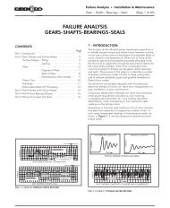
TECHNICAL INFORMATIONTable No. 1<strong>Belt</strong> Section, SheaveDiameters and StandardGroove Angles*Table No. 2Maximum AllowableOutside DiametersFor Cast Iron Pulleys37
TECHNICAL INFORMATIONDRIVE SHUTDOWN & THOROUGH INSPECTIONThe National Electric ManufacturersAssociation (NEMA) publishes recommendationsfor the minimumdiameter of sheaves to be used onGeneral Purpose electric motors.Purpose of the recommendations isto prevent the use of too smallsheaves, which can result in shaftor bearing damage because beltpull goes up as sheave diametergoes down.The NEMA Standard MG-1-14.42,November 1978 shows minimumrecommended sheave diametersas a function of frame number. Thetable below lists the NEMA frameassignments and minimum diameterrecommendations according tothe 1964 rerating program.Electric Motor Frames Assignmentsand Minimum V-<strong>Belt</strong> Sheave DiametersTable No. 3AFor other than the General Purpose AC motors (for example, DC motors,Definite Purpose motors, motors with special bearings or motors that arelarger than those covered by the NEMA standard), consult the motor manufacturerfor minimum sheave diameter recommendations. It is helpful to themanufacturer to include details of the application with your inquiry.38
TECHNICAL INFORMATIONMinimum Recommended Sprocket Outside Diameters forGeneral Purpose Electric Motors Synchronous <strong>Belt</strong>sData in the white area are from NEMA Standard MG-1-14-42, June 1972. Figures in black area are from MG-1-43, January 1968. The gray area is a composite ofelectric motor manufacturer data. They are generallyconservative and specific motors and bearings maypermit the use of a smaller motor sprocket. <strong>Co</strong>nsult themotor manufacturer.NOTE: For a given horsepower and speed, the totalbelt pull is related to the motor sprocket size. As thesize decreases, the total belt pull increases. Therefore,to limit the resultant load on motor and shaft bearings,NEMA lists minimum sprocket sizes for the variousmotors. The sprocket on the motor (<strong>Drive</strong>R sprocket)should be at least this large.Table No. 3B*These RPM are for 50 cycle electric motors.# Use 8.6 for Frame Number 444 T only.39
TECHNICAL INFORMATIONTECHNICAL TROUBLESHOOTING INFORMATION TOOLSMinimum RecommendedSheave Diameter By <strong>Belt</strong>Cross SectionMinimum RecommendedSprocket SizesTable No. 4BTable No. 4A40
Minimum RecommendedIdler DiametersTECHNICAL INFORMATIONTROUBLESHOOTING TECHNICAL INFORMATION TOOLSTable No. 5Minimum Center DistanceAllowances for <strong>Belt</strong>Installation and TakeupTable No. 641
Minimum Center DistanceAllowances for <strong>Belt</strong>Installation and TakeupTECHNICAL INFORMATIONTECHNICAL INFORMATIONTable No. 742
TECHNICAL INFORMATIONTECHNICAL INFORMATIONPoly Chain ® GT2 ® Installation& Tensioning AllowancesCenter Distance Allowance ForInstallation and TensioningTable No. 8Additional Center DistanceAllowance For InstallationOver Flanged Sprocket*(Add to Installation Allowance inAbove Table)43
TECHNICAL INFORMATIONTECHNICAL INFORMATIONTable No. 9Power Grip GT2 ® CenterDistance Allowance ForInstallation and TensioningAdditional Center Distanceallowance For InstallationOver Flanged Sprockets*(Add to Installation Allowance inAbove Table)44
TECHNICAL INFORMATIONDRIVE SHUTDOWN & THOROUGH INSPECTIONTable No. 10Power Grip ® Timing <strong>Belt</strong>sCenter Distance Allowancefor Installation andTensioningAdditional Center DistanceAllowance for InstallationOver Flanged Pulleys*(Add to Installation Allowance inAbove Table)Table No. 11Estimating <strong>Belt</strong> Length from<strong>Drive</strong> Dimensions(2 Pulleys)45
WORKSHEETHigh Speed <strong>Drive</strong> Survey and Energy Savings WorksheetCUSTOMER INFORMATIONDistributor ____________________________________________________________________________________________Customer ______________________________________________________________________________________________DRIVE INFORMATIONI.D. of <strong>Drive</strong> (location, number, etc.) ______________________________________________________________________Description of <strong>Drive</strong>N Equipment________________________________________________________________________Manufacturer of <strong>Drive</strong>N Equipment ______________________________________________________________________Horsepower Rating of Motor _______________ <strong>Drive</strong>N HP Load (Peak) _________________ (Normal) ______________Motor Frame Size _______________ Motor Shaft Dia. _______________ <strong>Drive</strong>N Shaft Dia. ___________________Speed:<strong>Drive</strong>R RPM _______________ ____________RPM Measured with <strong>Co</strong>ntact or Strobe Tachometer ■ Yes ■ No<strong>Drive</strong>N RPM _______________ ____________RPM Measured with <strong>Co</strong>ntact or Strobe Tachometer ■ Yes ■ NoSpeed Ratio _______________ Speed Up _______________________ or Speed Down ___________________Center Distance: Minimum _______________ Nominal ____________________ Maximum ________________________Existing <strong>Drive</strong> <strong>Co</strong>mponents: <strong>Drive</strong>R _______________________________ <strong>Drive</strong>N _______________________________<strong>Belt</strong>s ________________________________________ <strong>Belt</strong> Manufacturer _____________________________________Ambient <strong>Co</strong>nditions:Temperature _________________ Moisture _____________________ Oil, etc. _______________________________Abrasives __________________________________________________ Shock Load ___________________________Static <strong>Co</strong>nductivity Required? ■ Yes ■ NoMaximum Sprocket Diameter (OD) and Width Limitations (for guard clearance):<strong>Drive</strong>R: Max. OD __________ Max. Width ___________ <strong>Drive</strong>N: Max. OD ___________ Max. Width ____________Guard Description __________________________________________________________________________________Motor Mount:Double Screw Base? ■ Yes ■ No Motor Mounted on Sheet Metal? ■ Yes ■ NoAdequate Structure? ■ Yes ■ No Floating/Pivot Motor Base? ■ Yes ■ NoStart Up Load:%Motor Rating at Start Up __________ AC Inverter? ■ Yes ■ No Soft Start? ■ Yes ■ NoDuty Cycle:Number of Starts/Stops _________________________ times per _______________________ (hour, day, week, etc.)ENERGY SAVINGS INFORMATIONEnergy <strong>Co</strong>st per KW-Hour ______________________________________________________________________________Hours of Operation: ______ Hours per Day ______ Days per Week ______ Weeks per Year47
WORKSHEETLow Speed <strong>Drive</strong> Design Information SheetFor <strong>Drive</strong> Selections with Shaft Speeds Less Than 500 rpm<strong>Drive</strong> Layout(check one)Distributor: __________________________________________________________________________Customer: __________________________________________________________________________<strong>Drive</strong> Identification (location, number, etc.) ______________________________________________<strong>Drive</strong>R Information:Motor Nameplate DataRated Horsepower__________ Rated RPM __________ Efficiency ___________Rated Voltage __________ Rated Amps __________ Rated Torque __________Motor Reducer<strong>Belt</strong> <strong>Drive</strong> DrevenActual Motor Load ______________Motor Type: AC Three-Phase ■ AC Single-Phase ■ DC (Direct Current) ■Output Speed: <strong>Co</strong>nstant ■ Variable ■Measured Motor DataVoltage: Phase 1___________ Phase 2___________ Phase 3___________Amps: Phase 1___________ Phase 2___________ Phase 3___________Reducer Information:Reducer Type: Helical ■ Planetary ■ Cycloidal ■ Worm ■ <strong>Co</strong>mbination Type ■ Other ■Reducer Efficiency ________ Output RPM________ Reducer Ration________Rated Input HP/Torque ____________Rated Output HP/Torque ____________Existing <strong>Drive</strong> Information:<strong>Drive</strong> Type: Chain ■ V-<strong>Belt</strong> ■ Synchronous <strong>Belt</strong> ■If chain, Type; 2/#60, #80, etc. ________________ Lubed ■Current <strong>Drive</strong> Service Life ________________Unlubed ■<strong>Belt</strong> <strong>Drive</strong> onReducer Output Shaft<strong>Drive</strong>R Sprocket/Sheave ________(teeth/OD)<strong>Drive</strong>N Sprocket/Sheave ________(teeth/OD)<strong>Drive</strong>R Shaft Diameter________<strong>Drive</strong>N Shaft Diameter________Center Distance:Minimum____________ Nominal____________ Maximum____________Type of Center Distance Adjustment:_____________________________________Idler used: Yes ■ No ■ Inside ■ Backside ■Motor <strong>Belt</strong> <strong>Drive</strong>Reducer <strong>Drive</strong>n<strong>Drive</strong>N Information:Type of Equipment: ____________ Actual Horsepower Required ____________Required Operating RPM ____________ Required Speed Ration ____________Hours/Day __________ Days/Week __________ Weeks/Year __________Shock Load: Light ■ Moderate ■ Severe ■Start Up Load: % Overload____________Starting Torque ____________Special Requirements:Space Limitations:Maximum <strong>Drive</strong>R Dia.________________ Maximum <strong>Drive</strong>N Dia.______________Maximum <strong>Drive</strong>R Width _____________Maximum <strong>Drive</strong>N Width ____________Environmental <strong>Co</strong>nditions:Temperature Range____________ <strong>Belt</strong> <strong>Co</strong>nductivity Required ■Oil Mist ■ Oil Splash ■ Moisture ■ Abrasives ■<strong>Belt</strong> <strong>Drive</strong> onReducer Input Shaft<strong>Drive</strong> Sketch:48