1513.02 Switch, Pad-Mounted, Live-Front 15kV, 600 Amp
1513.02 Switch, Pad-Mounted, Live-Front 15kV, 600 Amp
1513.02 Switch, Pad-Mounted, Live-Front 15kV, 600 Amp

Create successful ePaper yourself
Turn your PDF publications into a flip-book with our unique Google optimized e-Paper software.
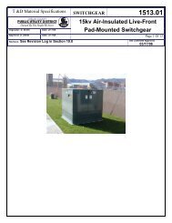
Material Specifications SWITCHGEAR <strong>1513.02</strong><strong>15kV</strong> <strong>600</strong><strong>Amp</strong> Air-Insulated <strong>Live</strong>-<strong>Front</strong><strong>Pad</strong>-<strong>Mounted</strong> Automatic Transfer <strong>Switch</strong>gearOrginator: D. Smith Date: 7/20/06With Supervisory ControlApproval: C. Bowman Date: 7/25/06 Page 1 Of 19Revision: See Revision Log in Section 22.0Std Committee Approval:Approved
Material Specifications SWITCHGEAR <strong>1513.02</strong><strong>15kV</strong> <strong>600</strong><strong>Amp</strong> Air-Insulated <strong>Live</strong>-<strong>Front</strong><strong>Pad</strong>-<strong>Mounted</strong> Automatic Transfer <strong>Switch</strong>gearOrginator: D. Smith Date: 7/20/06With Supervisory ControlApproval: C. Bowman Date: 7/25/06 Page 2 Of 19Revision: See Revision Log in Section 22.0Std Committee Approval:ApprovedTable Of Contents1 Scope....................................................................................................................................................... 32 General.................................................................................................................................................... 33 Reference Standards................................................................................................................................34 Connection Diagrams and Stock Numbers (Figure 1)............................................................................ 45 Ratings .................................................................................................................................................... 56 Enclosure................................................................................................................................................. 57 Grounding Provisions ............................................................................................................................. 88 Buses....................................................................................................................................................... 89 Cable Terminal <strong>Pad</strong>s............................................................................................................................... 810 Interrupter <strong>Switch</strong>es................................................................................................................................911 Fuse Mountings..................................................................................................................................... 1012 Fuse Handling Tool............................................................................................................................... 1013 Stored-Energy Operators ...................................................................................................................... 1014 Automatic Source-Transfer Control ..................................................................................................... 1215 Remote Supervisory Control & Indication .......................................................................................... 1516 Labeling ................................................................................................................................................ 1617 Instruction Manual................................................................................................................................ 1718 Certification .......................................................................................................................................... 1719 Packaging.............................................................................................................................................. 1720 Data to be Submitted with Bid.............................................................................................................. 1821 Data to be Furnished by Successful Bidder .......................................................................................... 1822 Specifications Revisions Log................................................................................................................ 19
Material Specifications SWITCHGEAR <strong>1513.02</strong><strong>15kV</strong> <strong>600</strong><strong>Amp</strong> Air-Insulated <strong>Live</strong>-<strong>Front</strong><strong>Pad</strong>-<strong>Mounted</strong> Automatic Transfer <strong>Switch</strong>gearOrginator: D. Smith Date: 7/20/06With Supervisory ControlApproval: C. Bowman Date: 7/25/06 Page 3 Of 19Revision: See Revision Log in Section 22.0Std Committee Approval:Approved1 Scope1.1 This specification covers the requirements for furnishing and delivering free-standing, selfcontained,cabinet enclosed <strong>15kV</strong> rated air-insulated live-front pad-mounted switchgear with <strong>600</strong>amp interrupter switches and/or 200 amp fuses with integral load interrupters configured as shownin Figure 1. In addition Automatic Source-Transfer Control & Remote Supervisory Control &Indication are provided.1.2 This switchgear is intended for use in 60 hertz, three-phase, 12470 volt grounded-WYEunderground distribution systems.1.3 This switchgear will be used for sectionalizing and protecting underground distribution expressfeeders, sub-loops, and laterals as well as switching and protecting transformers.1.4 This switchgear shall be designed for outdoor installation and operation. It shall be designed formounting on a concrete pad or Fiberglass Ground Sleeve.2 General2.1 The manufacturer shall be responsible for ensuring compatibility among all components of theswitchgear.2.2 The manufacturer shall be solely responsible for the performance of the basic switch componentsas well as the complete integrated assembly as rated.2.3 Upon the District's request, the manufacturer shall provide sufficient notice to allow the District orits representatives to inspect the switchgear during its manufacture and to witness any or all testsperformed on it.2.4 The manufacturer shall furnish, upon request, certified tests establishing the electrical ratings ofthe switchgear, including ratings of the basic switches and fuse components.2.5 The manufacturer shall provide product information for the pad-mounted switchgear with theinitial bid or as changes are made for, but not limited to, the following:2.5.1 Internal and external dimensions2.5.2 Electrical specifications2.5.3 Weight of unit2.5.4 Method of latching and stops on doors3 Reference StandardsExcept as modified by this specification, the switchgear furnished shall meet the requirements of the latestrevisions of all applicable ANSI, IEEE and NEMA standards in addition to the standards listed below:
Material Specifications SWITCHGEAR <strong>1513.02</strong><strong>15kV</strong> <strong>600</strong><strong>Amp</strong> Air-Insulated <strong>Live</strong>-<strong>Front</strong><strong>Pad</strong>-<strong>Mounted</strong> Automatic Transfer <strong>Switch</strong>gearOrginator: D. Smith Date: 7/20/06With Supervisory ControlApproval: C. Bowman Date: 7/25/06 Page 8 Of 19Revision: See Revision Log in Section 22.0Std Committee Approval:Approved3.0 mils. Paint and primer shall be lead free. A certified test abstract to indicatecompliance with these requirements shall be furnished upon request.6.8.2 The topcoat of the finish shall be dark green Munsell No. 7GY 3.29/1.5.6.8.3 A resilient closed-cell material, such as PVC gasket, shall be applied to the entireunderside of the enclosure bottom flange to protect the finish on this surface fromscratching during handling and installation. This material shall isolate the bottom flangefrom the alkalinity of a concrete foundation to help protect against corrosive attack.7 Grounding Provisions7.1 Grounding <strong>Pad</strong>s7.1.1 A ground connection pad shall be provided in each compartment of the pad-mountedgear. The pads shall be welded to the interior of the enclosure near the cable entrances.7.1.2 The pads shall be of unpainted copper-faced steel, unpainted stainless steel or unpaintedgalvanized steel. The pads shall be a minimum of 2 inches x 3-1/2 inches with two 1/2-13UNC tapped holes, a minimum 7/16 inch deep, spaced 1-3/4 inches center-to-center.7.1.3 The grounding pads shall be capable of carrying the fault duty of the switchgear.7.2 Grounding Studs8 Buses7.2.1 Each switch terminal, fuse terminal and compartment ground terminal shall have agrounding stud for attaching working grounds equipped with duckbill type clamps.7.2.2 The grounding studs shall be of galvanized steel.7.2.3 The compartment grounding studs shall be a minimum of 10 inches long.7.2.4 The grounding studs shall be located such that the working ground clamps may be easilyapplied or removed with a hotstick.7.2.5 The grounding studs shall be capable of carrying the fault duty of the switchgear.8.1 All buses shall be of copper or aluminum.8.2 All joints shall have suitable hardware and treatment to prevent harmful oxidation and loss ofoptimum contact pressure.8.3 Bus and interconnections shall withstand the stresses associated with short circuits up through themaximum rating of the switchgear.9 Cable Terminal <strong>Pad</strong>s9.1 All cable terminal pads shall be of tinned or silver-plated copper.
Material Specifications SWITCHGEAR <strong>1513.02</strong><strong>15kV</strong> <strong>600</strong><strong>Amp</strong> Air-Insulated <strong>Live</strong>-<strong>Front</strong><strong>Pad</strong>-<strong>Mounted</strong> Automatic Transfer <strong>Switch</strong>gearOrginator: D. Smith Date: 7/20/06With Supervisory ControlApproval: C. Bowman Date: 7/25/06 Page 10 Of 19Revision: See Revision Log in Section 22.0Std Committee Approval:Approved10.8 Ground studs shall be provided at all switch terminals. Ground studs shall also be provided on theground pad in each interrupter switch compartment. The momentary rating of the ground studsshall equal or exceed the short-circuit ratings of the pad-mounted gear.10.9 Bearings shall be maintenance-free or sealed type, with all-temperature lubricants, and shall becapable of free-operation through a specified temperature range.11 Fuse Mountings11.1 Each fuse compartment shall be equipped with mountings to accommodate three S&C SML-4Zpower fuseholders designed for S&C SM-4 power fuses.11.2 Three S&C SML-4Z power fuseholders will provided for each fuse compartment.11.3 All power fuse mountings are to have a built-in load-break device in the contact assembly toprovide live switching ability using only a standard hotstick with station prong or grappler,without the necessity of opening the line switches to isolate and replace a single blown fuse unit.11.4 <strong>Live</strong>-switching shall be accomplished by a firm steady opening pull on the fuse pull ring with ahook stick. No separate load-interrupting tool shall be required.11.5 Circuit interruption shall take place completely within the integral load interrupter with noexternal arc or flame.11.6 The integral load-interrupter and the fuse shall be provided with separate fault-closing contactsand current-carrying contacts. The fuse hinge shall be self-guiding and, together with the faultclosingcontacts, shall guide the fuse into the current carrying contacts during closing operations.Circuit-closing inrush currents and fault currents shall be picked up by the fault-closing contacts,not by the current-carrying contacts or interrupting contacts.11.7 A storage rack shall be provided in each fuse compartment to accommodate up to thee S&C SM-4fuse refill units.12 Fuse Handling Tool12.1 A fuse handling tool recommended for use by the fuse manufacturer shall be identified.13 Stored-Energy Operators13.1 Stored-energy operators shall be provided to operate the high-voltage source interrupter switchesthey shall be motor charged with solenoid trip-open and solenoid trip-closed operation.13.2 Stored-energy operators shall be equipped with an integral quick-make quick-break mechanisminstalled by the switch manufacturer, which shall store sufficient mechanical energy to open orclose the associated interrupter switch. The quick-make quick-break mechanism shall swiftly andpositively open and close the source interrupter switch independent of the speed of the chargingmotor or manual handle.
Material Specifications SWITCHGEAR <strong>1513.02</strong><strong>15kV</strong> <strong>600</strong><strong>Amp</strong> Air-Insulated <strong>Live</strong>-<strong>Front</strong><strong>Pad</strong>-<strong>Mounted</strong> Automatic Transfer <strong>Switch</strong>gearOrginator: D. Smith Date: 7/20/06With Supervisory ControlApproval: C. Bowman Date: 7/25/06 Page 11 Of 19Revision: See Revision Log in Section 22.0Std Committee Approval:Approved13.3 Stored-energy operators shall be equipped with tripping solenoids to release the stored energy toopen or close the associated source interrupter switch in response to a control signal.13.4 Stored-energy operators shall be equipped with a charging motor that shall charge the quick-makequick-break mechanism after each trip operation when voltage is present on the associated source.13.5 Pushbuttons shall be provided to permit local electrical trip-open and trip-closed operation.13.6 Local electrical operation shall be prevented when the source-transfer control is in the automaticmode. Stored-energy operators shall be provided with an operation selector that shall have thefollowing three positions:13.6.1 An operating position—when in this position, permits mechanical or electrical opening orclosing of the source interrupter switch.13.6.2 A lock position—when padlocked in this position, prevents all mechanical and electricaloperation.13.6.3 A charging position—when in this position, permits manual charging of the quick-makequick-break mechanism while prohibiting mechanical and electrical operation.13.7 Stored-energy operators shall be provided with a charging shaft and a removable manual charginghandle to allow manual charging of the quick-make quick-break mechanism in the event controlpower is lost. The manual charging shaft shall be accessible only when the operation selector is inthe “charging” position.13.8 Stored-energy operator shall be equipped with provisions for local mechanical trip-open and tripclosedoperation in the event control power is lost.13.9 Stored-energy operators shall be located in a grounded, steel-enclosed low-voltage controlcompartment. The control compartment shall provide complete isolation from high voltage to helpprotect operating personnel.13.10 Stored-energy operators shall be equipped with indicators to show whether the quick-make quickbreakmechanism is charged or discharged; whether the associated source interrupter switch is inthe open or closed position; and whether the stored-energy operator is in the switch-open orswitch-closed position.13.11 Each stored-energy operator shall be equipped with an operation counter.13.12 Stored-energy operators shall be provided with a decoupling feature to permit decoupling of thestored-energy operator from the associated source interrupter switch for testing and exercising ofthe stored-energy operator and source-transfer control without opening or closing the interrupterswitch and without exposure to high voltage. A tool shall not be required for decoupling orcoupling the switch and switch operator. An indicator shall be provided to show whether theoperator is coupled or decoupled. When the stored-energy operator is decoupled, the associatedsource interrupter switch shall be locked in the position it was in at the time of decoupling. It shall
Material Specifications SWITCHGEAR <strong>1513.02</strong><strong>15kV</strong> <strong>600</strong><strong>Amp</strong> Air-Insulated <strong>Live</strong>-<strong>Front</strong><strong>Pad</strong>-<strong>Mounted</strong> Automatic Transfer <strong>Switch</strong>gearOrginator: D. Smith Date: 7/20/06With Supervisory ControlApproval: C. Bowman Date: 7/25/06 Page 13 Of 19Revision: See Revision Log in Section 22.0Std Committee Approval:Approvedsequence voltage to detect any unbalance present as a result of an open phase condition.Automatic switching shall occur when the system unbalance exceeds a predeterminedunbalance-detect voltage for a period of time sufficient to confirm that the condition isnot transient.14.1.2.2 When normal phase voltages return to the preferred source, the control shall initiateretransfer to the preferred source as described above.14.2 Control Features14.2.1 The operating characteristics of the source-transfer control and its voltage-, current-, andtime-related operating parameters shall be field programmable and entered into thecontrol by means of a keypad. To simplify entry of this information, a menu arrangementshall be utilized including keys dedicated to the operating characteristics and to each ofthe operating parameters. Entry of an access code shall be necessary before any operatingcharacteristic or operating parameter can be changed.14.2.2 All operating characteristics and operating parameters shall be available for review on aliquid-crystal display with backlighting.14.2.3 Light-emitting diode lamps shall be furnished for indicating the presence of acceptablevoltage on each high-voltage source.14.2.4 A light-emitting diode lamp shall be furnished for indicating that both stored-energyoperators are coupled to their respective interrupter switches and in the correct positions,the control is in the automatic mode, the operation selector for each stored-energyoperator is in the operating position, and all control circuitry is properly connected forautomatic transfer. The display, when not being used to show menu information, shallshow messages explaining why this lamp is not lighted.14.2.5 A selector switch shall be furnished for choosing manual or automatic operating mode. Inthe manual mode, local electrical trip-open and trip-closed operation by means ofpushbuttons shall be enabled while automatic switching shall be inhibited.14.2.6 Test keys shall be furnished for simulating loss of voltage on each of the two sources, aswell as for checking the functioning of the lamps, display, and keypad.14.2.7 The control shall include built-in diagnostics for analyzing system events. The deviceshall automatically record system status and source-transfer control status every time acontrol operation occurs. All such operations shall be indicated by the illumination of alight-emitting diode lamp and shall be available for display by means of a dedicated eventkey.14.2.8 The present source voltage and current inputs, and the present status of discrete inputs toand outputs from the control shall be available for display by means of a dedicatedexamine key.
Material Specifications SWITCHGEAR <strong>1513.02</strong><strong>15kV</strong> <strong>600</strong><strong>Amp</strong> Air-Insulated <strong>Live</strong>-<strong>Front</strong><strong>Pad</strong>-<strong>Mounted</strong> Automatic Transfer <strong>Switch</strong>gearOrginator: D. Smith Date: 7/20/06With Supervisory ControlApproval: C. Bowman Date: 7/25/06 Page 14 Of 19Revision: See Revision Log in Section 22.0Std Committee Approval:Approved14.2.9 The control shall have the capability to automatically calibrate to a known voltage oneach source. This capability shall be keypad selectable.14.3 Construction Features14.3.1 The source-transfer control shall use an advanced microprocessor and other solid-stateelectronic components to provide the superior reliability for use in power equipment. Allcomponents shall be soldered on printed circuit boards to minimize the number ofinterconnections for increased reliability.14.3.2 All interconnecting-cable connector pins and receptacle contacts shall be gold-overnickelplated to minimize contact pressure.14.3.3 The surge withstand capability of the control shall be verified by subjecting the device toboth the ANSI Surge Withstand Capability Test (ANSI Standard C37.90.1) and to a 5-kV, 3.75-joule capacitive-discharge test. For the capacitive-discharge test, a suitablecapacitor shall be charged to 5 kV, and shall then be used to discharge 3.75 joules intoeach input circuit and each output circuit of the device.14.3.4 To identify and eliminate components that might be prone to early failure, the controlshall be subjected to a dielectric test, a functional check, and a 72-hour screening testfollowed by a second functional check. For the screening test, the device shall beenergized at rated control voltage while subjected to a maximum-design operatingtemperature of +70ºC for 24 hours, followed by 48 hours during which the temperature iscycled repeatedly between –40ºC and +70ºC.14.3.5 The control shall be located in the grounded, steel-enclosed low-voltage compartmentwith the stored-energy operators. The control compartment shall provide isolation fromhigh voltage.14.4 Voltage Sensing and Control Power14.4.1 Voltage sensing and control power shall be provided by three capacitively coupledvoltage sensors on the line side of each source interrupter switch.14.4.2 To maximize usable cable-training space within the pad-mounted gear, the voltagesensors shall directly replace the lower apparatus insulators of the source interrupterswitches. Furthermore, the voltage sensors shall be constant-current-output devices thatdo not require primary fuses.14.4.3 The output of the voltage sensors shall be directly proportional to line-to-ground voltageand shall have relay accuracy over an ambient temperature range of –40ºF to +160ºF.14.4.4 Each voltage sensor shall be equipped with a secondary-side protective device to preventdamage to the voltage sensor in the event that the secondary circuit is inadvertentlyopened or the burden is removed.
Material Specifications SWITCHGEAR <strong>1513.02</strong><strong>15kV</strong> <strong>600</strong><strong>Amp</strong> Air-Insulated <strong>Live</strong>-<strong>Front</strong><strong>Pad</strong>-<strong>Mounted</strong> Automatic Transfer <strong>Switch</strong>gearOrginator: D. Smith Date: 7/20/06With Supervisory ControlApproval: C. Bowman Date: 7/25/06 Page 15 Of 19Revision: See Revision Log in Section 22.0Std Committee Approval:Approved14.5 Additional Features:14.5.1 An overcurrent-lockout feature shall be provided to prevent an automatic transferoperation that would close a source interrupter switch into a fault. The feature shallinclude a light-emitting diode lamp for indicating when a lockout condition has occurred,a reset key for manually resetting the lockout condition, and three current sensors foreach source. Provisions shall be furnished for manually resetting the overcurrent-lockoutfeature from a remote location. Test keys shall be provided for simulating an overcurrentcondition on each source.14.5.2 Remote-indication provisions shall be provided to permit remote monitoring of thepresence or absence of preferred- and alternate-source voltage; the operating mode of thesource-transfer control (i.e., automatic or manual); and the status of the indicating lampsovercurrent lockout.14.5.3 A test panel shall be provided to permit the use of an external, adjustable three-phasesource to verify, through independent measurement, the response of the control to lossof-source,phase-unbalance, and (where applicable) overcurrent-lockout conditions.14.5.4 A communications card shall be provided to permit local loading, to a user-furnishedpersonal computer, of system events recorded by the source-transfer control; operatingcharacteristics and voltage-, current-, and time-related operating parameters programmedin the control; discrete inputs and outputs from the control; and messages explaining whythe indicating lamp furnished in is not lighted. The communications card shall also permitlocal downloading of the user’s standard operating parameters from the personalcomputer to the control.14.5.5 A maintenance cable shall be provided for connecting the optional source-transfer controlcommunications card to a user-furnished personal computer having a (25-pin, 9-pin)serial communication port.15 Remote Supervisory Control & Indication15.1.1 A GE IBOX RTU shall be provided and installed and to support the following functions.15.1.1.1 The RTU shall support a DNP 3.0 Ethernet PPP Protocol.15.1.1.2 Connection shall be a TCP/IP RJ45 Ethernet connector.15.1.2 Supervisory control provisions shall be provided to permit switch operation from aremote location.15.1.2.1 Control Functions• Auto/Manual• Ability to Open/Close Each <strong>Switch</strong>• Ability to reset the Overcurrent Lockout
Material Specifications SWITCHGEAR <strong>1513.02</strong><strong>15kV</strong> <strong>600</strong><strong>Amp</strong> Air-Insulated <strong>Live</strong>-<strong>Front</strong><strong>Pad</strong>-<strong>Mounted</strong> Automatic Transfer <strong>Switch</strong>gearOrginator: D. Smith Date: 7/20/06With Supervisory ControlApproval: C. Bowman Date: 7/25/06 Page 16 Of 19Revision: See Revision Log in Section 22.0Std Committee Approval:Approved16 Labeling15.1.2.2 Status Functions via dry contacts the following16.1 Hazard-Alerting Signs• Indicate Position of Local “Auto/Manual” <strong>Switch</strong>• Indicate Position of Remote “Auto/Manual” <strong>Switch</strong>• Source Indication – Primary Source / Alternate Source• “AUTO TRANSFER READY” – Yes/No16.1.1 All external doors shall be provided with “Warning—Keep Out—Hazardous VoltageInside—Can Shock, Burn, or Cause Death” signs.16.1.2 The inside of each door shall be provided with a “Danger—Hazardous Voltage—Failureto Follow These Instructions Will Likely Cause Shock, Burns, or Death” sign. The textshall further indicate that operating personnel must know and obey the employer’s workrules, know the hazards involved, and use proper protective equipment and tools to workon this equipment.16.1.3 Interrupter switch compartments shall be provided with “Danger” signs indicating that“<strong>Switch</strong>es May Be Energized by Backfeed.”16.1.4 Fuse compartments shall be provided with “Danger” signs indicating that “Fuses May BeEnergized by Backfeed.”16.1.5 Barriers used to prevent access to energized live parts shall be provided with “Danger—Keep Away—Hazardous Voltage—Will Shock, Burn, or Cause Death” signs.16.2 Nameplate16.2.1 The outside of each door, or set of double doors, of the switchgear shall be provided witha durable corrosion-resistant nameplate indicating:·16.2.1.1 Name of manufacturer16.2.1.2 Date of manufacture16.2.1.3 Model No.16.2.1.4 Catalog No.16.2.1.5 Serial No.16.3 Ratings Label16.3.1 The inside of each door, or set of double doors, shall be provided with a ratings label.16.3.2 This label shall include the ratings required in section 5.0 of this specification.16.4 Connection Diagram
Material Specifications SWITCHGEAR <strong>1513.02</strong><strong>15kV</strong> <strong>600</strong><strong>Amp</strong> Air-Insulated <strong>Live</strong>-<strong>Front</strong><strong>Pad</strong>-<strong>Mounted</strong> Automatic Transfer <strong>Switch</strong>gearOrginator: D. Smith Date: 7/20/06With Supervisory ControlApproval: C. Bowman Date: 7/25/06 Page 17 Of 19Revision: See Revision Log in Section 22.0Std Committee Approval:Approved16.4.1 The inside of each door, or set of double doors, and the inside of each switch operatinghub access cover shall be provided with a three-line connection diagram of theswitchgear.16.4.2 The diagram shall show the interrupter switches, fuses with integral load interrupters andbus.16.5 Compartment and Phase Identification16.5.1 The number of each compartment shall be clearly labeled with a decal on the inside of theswitchgear cabinet. The preferred location for each decal is on the face of the cabinetdirectly above each compartment.16.5.2 Each switch and fuse position phase shall be labeled with a decal on the inside of theswitchgear cabinet. Phase identification labels shall be located on the face of the cabinetdirectly above each phase position.17 Instruction ManualOne instruction manual covering installation, operation and maintenance of the equipment shall beprovided with each switchgear cabinet. This manual shall be packaged in a weatherproof bag orenvelope and secured on the inside of the door of compartment no. 1.18 Certification18.1 Upon the District's request, the manufacturer shall provide certified test reports verifying that theequipment meets or exceeds the electrical ratings, tamper resistance and finish required by thisspecification.19 Packaging19.1 Each switchgear shall be completely assembled and packaged in accordance with goodcommercial practice to ensure safe delivery without damage to the finish or any other part of theunit.19.2 Provisions shall be made to protect switchgear shipped on flatbed trucks from contamination ofthe cabinet exterior and interior from rocks, dirt, insects and other foreign materials encounteredin shipment.19.3 Each switchgear shall be shipped on a nonreturnable wood pallet designed for handling with aforklift. Pallets shall have a minimum of 3-1/2 inches of vertical clearance for the forks. Palletsshall be of adequate strength to withstand normal shipping and handling of the switch.19.4 To reduce shipping costs, switchgear may be doubled stacked. If this shipping method isproposed, a detail sketch shall be provided and approved by the District prior to shipment.19.5 <strong>Switch</strong>gear shall be shipped so that they may be removed from the truck or trailer by forklift.
Material Specifications SWITCHGEAR <strong>1513.02</strong><strong>15kV</strong> <strong>600</strong><strong>Amp</strong> Air-Insulated <strong>Live</strong>-<strong>Front</strong><strong>Pad</strong>-<strong>Mounted</strong> Automatic Transfer <strong>Switch</strong>gearOrginator: D. Smith Date: 7/20/06With Supervisory ControlApproval: C. Bowman Date: 7/25/06 Page 18 Of 19Revision: See Revision Log in Section 22.0Std Committee Approval:Approved19.6 No material or other switchgear shall be stacked or carried on top of the switchgear.20 Data to be Submitted with Bid20.1 Each bidder shall submit with its proposal the data listed below. The bidder shall submit adescription of any changes, additions, or exceptions to this specification it proposes, together withthe reasons for the departure. Product evaluation and conformance to specification will bedetermined on the basis of the information submitted. The drawings and data furnished must besufficient in detail and clarity to enable making a complete and positive check with the technicalprovisions of this specification.20.1.1 Outline drawings with overall dimensions including those dimensions described inSections 5.120.1.2 Statement of type of stainless steel to be used.20.1.3 Total weight of complete switchgear assembly.20.1.4 Electrical schematics.20.1.5 Indicate construction and testing compliance per latest revision of ANSI C57.12.28.20.1.6 One copy of an instruction book covering installation, operation, and maintenance of theequipment.21 Data to be Furnished by Successful Bidder21.1 The successful bidder shall supply:21.1.1 Outline drawings with overall dimensions; see Sections 5.1, 15.5, and 15.6, dimensionrequirements.21.1.2 One copy of an instruction book covering installation, operation, and maintenance of theequipment shall be packaged in a water resistant envelope and placed inside each switch.21.1.3 Time-current curves of all fuses and protective relays.21.1.4 One certified copy of all standard tests except as noted below.21.1.5 One certified copy of the enclosure coating system performance tests required by ANSIC57.12.28 only when requested.21.1.6 One certified copy of the enclosure security performance tests required by ANSIC57.12.28 only when requested.
Material Specifications SWITCHGEAR <strong>1513.02</strong><strong>15kV</strong> <strong>600</strong><strong>Amp</strong> Air-Insulated <strong>Live</strong>-<strong>Front</strong><strong>Pad</strong>-<strong>Mounted</strong> Automatic Transfer <strong>Switch</strong>gearOrginator: D. Smith Date: 7/20/06With Supervisory ControlApproval: C. Bowman Date: 7/25/06 Page 19 Of 19Revision: See Revision Log in Section 22.0Std Committee Approval:Approved22 Specifications Revisions Log# Date Section Description1 7/24/06 14 & 15 Modified Spec 1513_02 to 1513_03 PM with Transfer SW & Supervisory Control2 9/5/06 All Revised per review from S&C and Federal Pacific.3 9/15/06 15 Modified Protocol required45678