- LFI type CLFI-<st<strong>ro</strong>ng>02</st<strong>ro</strong>ng> manufactured by Common S.A. II 2G EEx ia IICT6.- LFK type CLFK-<st<strong>ro</strong>ng>02</st<strong>ro</strong>ng> manufactured by Common S.A. II 2G EEx ia IICT6.Permitted parameters of the intrinsically safe supply circuits (U i ,I i , P i ), maximuminductance and internal capacitance (L i , C i )HF LFI LFKU i = 16 V DC U i = 15,5 V DC U i = 15,5 V DCI i = 25 mA I i = 52 mA I i = 52 mAP i = 64 mW P i = 169 mW P i = 169 mWL i = 50 μH L i ≈ 40 μH L i ≈ 0C i = 30 nF C i = 28 nF C i ≈ 0Rated operation parameters of applied pulse transmitters:reed contactCLFK-<st<strong>ro</strong>ng>02</st<strong>ro</strong>ng>:rated voltageU n = 5÷15,5 V DC,closed contact resistance R z = 500Ω ÷ 2 kΩ ,open contact resistance R o > 100 MΩ ,maximum switching frequency f p = 500 Hz .inductive CLFI-<st<strong>ro</strong>ng>02</st<strong>ro</strong>ng> NJ0,8-5GM-Nrated voltage U n = 5÷15,5 V U n = 5÷16 V,non active transmitter current I L < 1,2 mA , I L < 1,2 mA,active transmitter current I H > 2,1 mA , I H > 2,1 mA,load resistance R n < 1 kΩ , R n < 1 kΩ,maximum switching frequency f p = 200 Hz, f p = 5 kHz.Depending on the transmitter state, (active or non active), a voltage d<strong>ro</strong>p on the 1 kΩ resisto<strong>ro</strong>ccurs. For the above mentioned transmitter current values (according to PN EN 60947-5-6:20<st<strong>ro</strong>ng>02</st<strong>ro</strong>ng>) the input voltage values may be as follows:- non active state U L < 1,2 V,- active state U H > 2,1 V.Electrical outputs f<strong>ro</strong>m HF transmitters installed in the gas meter bodyHigh frequency transmitters may be installed in the gas meter body, over the turbine wheel o<strong>ro</strong>ver the reference wheel which number of cogs corresponds to the number of turbine wheelvanes. The modulating element of the HF transmitter magnetic field is either the turbine wheelor the reference wheel. The transmitter is installed in the tap shown in Fig. 3. The tap isp<strong>ro</strong>vided with M16 x 1,5 thread (Fig. 4).INSTALLATION OF THE HF TRANSMITER IN THE <st<strong>ro</strong>ng>GAS</st<strong>ro</strong>ng> METER BODY REQUIRES HIGHACCURACY. ALSO SPECIAL ELECTRONIC CONTROL DEVICES SHOULD BE USED. THEREFOREIT MAY ONLY BE PERFORMED BY THE MANUFACTURER OR BY THE AUTHORISEDREPRESENTATIVE.The <st<strong>ro</strong>ng>CGT</st<strong>ro</strong>ng>-<st<strong>ro</strong>ng>02</st<strong>ro</strong>ng> Turbine Gas Meters may be equipped with maximum 4 p<strong>ro</strong>ximity inductive HFtransmitters:- two HF transmitter over the turbine wheel,11
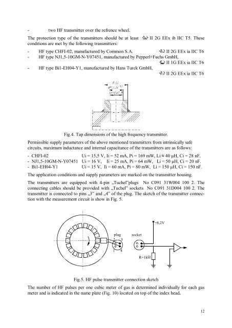
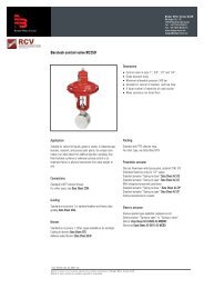
- two HF transmitter over the refrence wheel.The p<strong>ro</strong>tection type of the transmitters should be at leastconditions are met by the following transmitters:II 2G EEx ib IIC T5. These- HF type CHFI-<st<strong>ro</strong>ng>02</st<strong>ro</strong>ng>, manufactured by Common S.A. II 2G EEx ia IIC T6- HF type NJ1,5-10GM-N-Y07451, manufactured by Pepperl+Fuchs GmbH,II 1G EEx ia IIC T6- HF type Bi1-EH04-Y1, manufactured by Hans Turck GmbH,II 2G EEx ia IIC T6Fig.4. Tap dimensions of the high frequency transmitter.Permissible supply parameters of the above mentioned transmitters f<strong>ro</strong>m intrinsically safecircuits, maximum inductance and internal capacitance of the transmitters are as follows:- CHFI-<st<strong>ro</strong>ng>02</st<strong>ro</strong>ng> Ui = 15,5 V, Ii = 52 mA, Pi = 169 mW, Li ≈ 40 μH, Ci = 28 nF.- NJ1,5-10GM-N-Y07451 Ui = 16 V, Ii = 25 mA, Pi = 64 mW, Li = 50 μH, Ci = 20 nF.- Bi1-EH04-Y1 Ui = 15 V, Ii = 60 mA, Pi = 80 mW, Li = 150 μH, Ci = 150 nF.The application conditions and supply parameters are marked on the transmitter housing.The transmitters are equipped with 4-pin „Tuchel”plugs No C091 31W004 100 2. Theconnecting cables should be p<strong>ro</strong>vided with „Tuchel” sockets No C091 31D004 100 2. Thetransmitter is connected to pins „3” and „4” of the plug. The sketch of the transmitter connectionwith the measurement circuit is show in Fig. 5.+8,2Vplug2 3socket1 4R=1k ΩFig.5. HF pulse transmitter connection sketchThe number of HF pulses per one cubic meter of gas is determined individually for each gasmeter and is indicated in the name plate (Fig. 10) located on top of the index head.12