Download (9.51 MB) - Sussex Plumbing Supplies
Download (9.51 MB) - Sussex Plumbing Supplies
Download (9.51 MB) - Sussex Plumbing Supplies

You also want an ePaper? Increase the reach of your titles
YUMPU automatically turns print PDFs into web optimized ePapers that Google loves.
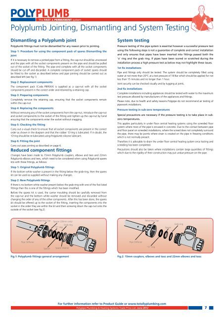
The FAST & PERMANENT systemPolyplumb Jointing, Dismantling and System TestingDismantling a Polyplumb jointPolyplumb fittings must not be dismantled for any reason prior to jointing.Step 1: Procedure for using the component pack of spares Dismantling thejointand the pipe with all the socket components present on the pipe end should be pulledout of the socket of the fitting. The pipe end complete with all the socket componentsshould be cut off and discarded. A complete component pack of socket spares shoulddescribed left (see fig.1)Step 2: Replacement componentsThe component pack (Code: PB95XX) is supplied as a cap-nut with all the socketcomponents present in the correct order and retained by a retaining cap.Step 3: Preparing componentsCompletely remove the retaining cap, ensuring that the socket components remainwithin the cap-nut.Step 4: Replacing the componentsWithout removing any of the socket components from the cap-nut, introduce the cap-nutand socket components to the socket of the fitting and tighten up the cap-nut by handensuring that the components enter the socket without snagging.Step 5: Checking the fittingCarry out a visual check to ensure that all socket components are present in the correctorder as shown in the diagram and that the rubber ’O’ring is lubricated. If in doubt, the‘O’ring should be re-lubricated using Polyplumb silicone lubricant.Step 6: Fitting the jointReduced component fittingsChanges have been made to 15mm Polyplumb couplers, elbows and tees and 22mmPolyplumb elbows and tees, which need to be considered when using Polyplumb spareskits with these fittings, as follows:System testingPressure testing of the pipe system is essential however a successful pressure testusing the following steps is not a guarantee of complete and correct installationand only ensures that pipes have been inserted into fittings passed both the‘o’ ring and the grab ring. If pipes have been scored or scratched during theinstallation process a high pressure test as below may not highlight these issues.1st fix installationsPipe and fittings only should be tested. The system should be completely filled usingwater at not more than 20°C at a test pressure of 18 Bar which should be applied for notless than 15 minutes and no longer than 1 hour.2nd fix installationsComplete installations including appliances should be tested with water to the maximumtest pressure allowed by manufacturers of the appliances and fittings.Please note, due to health and safety reasons Polypipe do not recommend air testing ofpipework installations.Pressure testing in sub-zero temperaturesSpecial precautions are necessary if the pressure testing is to take place in subzerotemperatures.This applies particularly in under floor central heating systems using the screeded floorsystem where most of the pipe is encased in concrete. Due to the contact between pipeand floor panel on screeded installations, where the screed does not completely surroundthe pipe, there may be points where strain is created on the pipe in freezing conditionswhich is not normally present.Therefore it is advisable to drain the under floor central heating system once testing andscreeding has been completed.Precautions should also be taken where installations contain large quantities of fittingswhich due to the rigidity of their construction may put undue pressure on the pipe.Step 1: Original Polyplumb fittingsIf the bottom white washer is present in the fitting below the grab-ring, then the spareskit can be used as supplied without making any changes.Step 2: New Polyplumb fittingsIf there is no bottom white washer present below the grab-ring with one of the five listedfittings then this is one of the fittings which has been modified.Before the spares kit is used, the carrier moulding should be carefully removed fromthe cap-nut and the bottom white washer should be removed and discarded withoutchanging the order of any of the other components. After this has been done, the spareskit should be offered up to the socket of the fitting, inserting the components into thesocket in the order they are within the kit and then screwing down the cap-nut onto theoutside of the socket (see fig.2).Retaining CapSpacer (28mm only)Grab ring“O” ringRetaining CapSpacerGrab ringPipe StiffenerPipe StiffenerSpacerSpacer Washer“O” ringFig.1: Polyplumb fittings general arrangementFig.2: 15mm couplers, elbows and tees and 22mm elbows and teesFor further information refer to Product Guide or www.totallyplumbing.comPolypipe <strong>Plumbing</strong> & Heating Systems Trade Price List: June 20127