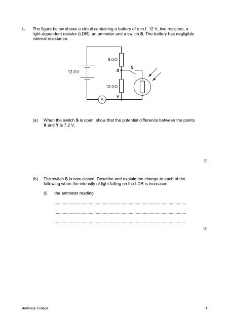
1. The figure below shows a circuit containing a battery of e.m.f. 12 V ...
1. The figure below shows a circuit containing a battery of e.m.f. 12 V ...
1. The figure below shows a circuit containing a battery of e.m.f. 12 V ...

You also want an ePaper? Increase the reach of your titles
YUMPU automatically turns print PDFs into web optimized ePapers that Google loves.
(b) (i) Use Fig. 2 to determine the maximum possible current that can be drawnfrom the cell.current = .............................. A[1](ii)Calculate the internal resistance r <strong>of</strong> the cell.r = .............................. Ω[2](iii)Suggest why it may not be advisable to maintain the current determined in(b)(i) for a long time.................................................................................................................................................................................................................................[1][Total 5 marks]Ambrose College 3
3. <strong>The</strong> following <strong>figure</strong> <strong>shows</strong> a potential divider <strong>circuit</strong> designed as a touch-sensor.VfingerX Y 168 kΩ5.0 V<strong>The</strong> <strong>battery</strong> has negligible internal resistance and the voltmeter has infinite resistance.(a)Explain why the voltmeter reading is zero when there is nothing connectedbetween the contacts X and Y...................................................................................................................................................................................................................................................[1](b)When the finger makes contact between X and Y, the voltmeter reading changesfrom 0 V to 3.4 V because <strong>of</strong> the electrical resistance <strong>of</strong> the skin. Use thisinformation to calculate the electrical resistance <strong>of</strong> the skin between the twocontacts.resistance = .................................. kΩ[3][Total 4 marks]4. A convenient unit <strong>of</strong> energy is the kilowatt hour (kW h).(a)Define the kilowatt hour...................................................................................................................................................................................................................................................[1]Ambrose College 4
(b)A <strong>12</strong>0 W filament lamp transforms 5.8 kW h. Calculate the time in seconds forwhich the lamp is operated.time = .............................. s[2][Total 3 marks]5. (a) (i) Define electrical resistivity.................................................................................................................................................................................................................................................................................................................................................................................................................................................................[2](ii)Explain why the resistivity rather than the resistance <strong>of</strong> a material is givenin tables <strong>of</strong> properties <strong>of</strong> materials.................................................................................................................................................................................................................................................................................................................................................[1]Ambrose College 5
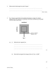
(b)lA<strong>The</strong> diagram above <strong>shows</strong> a copper rod <strong>of</strong> length l = 0.080m, having a crosssectionalarea A = 3.0 × 10 –4 m 2 .<strong>The</strong> resistivity <strong>of</strong> copper is <strong>1.</strong>7 × 10 –8 Ω m.Calculate the resistance between the ends <strong>of</strong> the copper rod.resistance = ........................ Ω[2][Total 5 marks]6. (a) A rechargeable <strong>battery</strong> is put on charge for 4.0 hours with a constant current <strong>of</strong>50 mA from a 6.0 V supply. Calculate(i)the charge which flows through the <strong>battery</strong> in this timecharge = ..................................................... C[3](ii)the energy which has been provided from the supply.energy = ...................................................... J[2]Ambrose College 6
(b)In what form does a <strong>battery</strong> store energy?.............................................. energy[1](c)<strong>The</strong> charged <strong>battery</strong> has an e.m.f <strong>of</strong> 4.5 V and is connected to a 48 Ω resistor.<strong>The</strong> potential difference across the resistor is found to be 4.0 V. <strong>The</strong> current isconstant during the 45 minutes the <strong>battery</strong> discharges. Calculate(i)the internal resistance <strong>of</strong> the <strong>battery</strong> when in useinternal resistance = ..................................................... Ω[2](ii)the energy supplied to the 48 Ω resistor in this timeenergy = ...................................................... J[3](iii)the fraction <strong>of</strong> the initial energy (a)(ii) which the energy in (c)(ii) represents.fraction = ......................................................[1]Ambrose College 7
(d)Explain why the value <strong>of</strong> the internal resistance calculated in (c)(i) is only reliableto 1 significant <strong>figure</strong>.........................................................................................................................[1][Total 13 marks]7. <strong>The</strong> I/V characteristic <strong>of</strong> a filament lamp is shown in Fig. <strong>1.</strong>6I/A5432100<strong>12</strong> 3 4 5 6 7 8V/VFig. 1(i)On Fig. 1, mark a point on the graph, and label it with the letter M, where theresistance <strong>of</strong> the filament lamp is maximum.[1](ii) Calculate the power dissipated by the lamp when operating at 6.0 V.power = ........................... W[3]Ambrose College 8
(iii)Fig. 2 <strong>shows</strong> the same filament lamp and a resistor <strong>of</strong> resistance <strong>1.</strong>2 Ωconnected in series with a <strong>battery</strong>.2.0A4.5Vrlamp<strong>1.</strong>2ΩVFig. 2<strong>The</strong> <strong>battery</strong> has e.m.f. 4.5 V and internal resistance r. <strong>The</strong> voltmeter has veryhigh resistance. <strong>The</strong> current in the <strong>circuit</strong> is 2.0 A.1 Show, with the help <strong>of</strong> Fig. 1, that the voltmeter reading is 3.4 V.[3]2 Calculate the internal resistance r <strong>of</strong> the <strong>battery</strong>.resistance = .............................. Ω[2][Total 9 marks]Ambrose College 9
8. (i) Use energy considerations to distinguish between potential difference (p.d.) andelectromotive force (e.m.f.).....................................................................................................................................................................................................................................................................................................................................................................................................................................................................................................[2](ii)Here is a list <strong>of</strong> possible units for e.m.f. or p.d.J s –1 J A –1 J C –1State which one is a correct unit: ....................................................................[1][Total 3 marks]9. (a) <strong>The</strong> diagram <strong>below</strong> <strong>shows</strong> how the resistance <strong>of</strong> a thermistor varies withtemperature.500400resistance / Ω30020010000 20 40 60 80 100temperature / ºC(i)Describe qualitatively how the resistance <strong>of</strong> the thermistor changes as thetemperature rises.................................................................................................................[1]Ambrose College 10
(ii) <strong>The</strong> change in resistance between 80 °C and 90 °C is about 15 Ω.State the change in resistance between 30 °C and 40 °C.................................................................................................................[1](iii)Describe, giving a reason, how the sensitivity <strong>of</strong> temperature measurementusing this <strong>circuit</strong> changes over the range <strong>of</strong> temperatures shown on thediagram.................................................................................................................................................................................................................................................................................................................................................[2](b)Fig. 1 <strong>shows</strong> how the resistance <strong>of</strong> a thermistor varies with temperature.500400resistance / Ω30020010000 20 40 60 80 100temperature / ºCFig. 1Ambrose College 11
Fig. 2 <strong>below</strong> <strong>shows</strong> a temperature sensing potential divider <strong>circuit</strong> where thisthermistor may be connected, between terminals A and B, in series with aresistor.A6.0 V d.c.Bresistor(i)Fig. 2Draw the <strong>circuit</strong> symbol for a thermistor on Fig. 2 in the space betweenterminals A and B.[1](ii)A voltmeter is to be connected to the <strong>circuit</strong> to indicate an increasing p.d.when the thermistor detects an increasing temperature. On Fig. 2, draw the<strong>circuit</strong> connections for a voltmeter to measure a p.d. that rises withincreasing temperature.[1](iii)<strong>The</strong> value <strong>of</strong> the resistor in Fig. 2 is 200 Ω. <strong>The</strong> thermistor is at 65 °C. Usedata from Fig. 1 to show that the current in the <strong>circuit</strong> is about 0.02 A.[3](iv)Calculate the p.d. across the 200 Ω resistor at 65 °C.p.d. across resistor = .................. V[1][Total 10 marks]Ambrose College <strong>12</strong>
10. State Ohm’s law in words.......................................................................................................................................................................................................................................................................................................................................................................................................[Total 2 marks]Ambrose College 13