TEMPERATURE AND HUMIDITY CONTROLLER FOR TWO ... - Coster
TEMPERATURE AND HUMIDITY CONTROLLER FOR TWO ... - Coster
TEMPERATURE AND HUMIDITY CONTROLLER FOR TWO ... - Coster

Create successful ePaper yourself
Turn your PDF publications into a flip-book with our unique Google optimized e-Paper software.
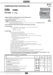
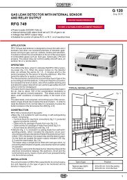
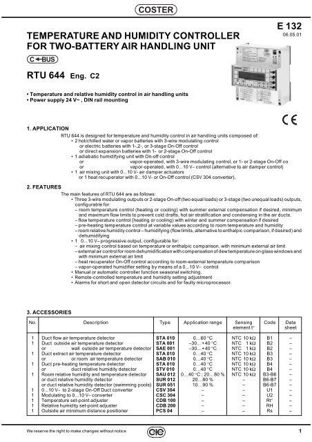
COSTERE 132 - RTU 644 C2 Eng. 06.05.01<strong>TEMPERATURE</strong> <strong>AND</strong> <strong>HUMIDITY</strong> <strong>CONTROLLER</strong><strong>FOR</strong> <strong>TWO</strong>-BATTERY AIR H<strong>AND</strong>LING UNITCBUSE 13206.05.01RTU 644 Eng. C2• Temperature and relative humidity control in air handling units• Power supply 24 V~ , DIN rail mounting1. APPLICATIONRTU 644 is designed for temperature and humidity control in air handling units composed of:• 2 hot/chilled water or vapor batteries with 3-wire modulating controlor electric batteries with 1-,2-, or 3-stage On-Off controlor direct expansion batteries with 1- or 2-stage On-Off control• 1 adiabatic humidifying unit with On-off controlorvapor-operated, with 3-wire modulating control, or 1- or 2-stage On-Off coorvapor-operated, with 0...10 V– control (alternative to air damper control)• 1 air mixing unit with 0...10 V- air damper actuatorsor 1 heat recuperator with 0...10 V- or On-Off control (CSV 304 converter).2. FEATURESThe main features of RTU 644 are as follows:• Three 3-wire modulating outputs or 2-stage On-off (two equal loads) or 3-stage (two unequal loads) outputs,configurable for:– room temperature control (heating or cooling) with summer external compensation if desired, minimumand maximum flow limits to prevent cold drafts, hot air stratification and condensing in the air ducts.– flow temperature control (heating or cooling) with winter and summer compensation if desired– pre-heating temperature control at variable values according to room temperature and humidity– room relative humidity control – humidifying (flow limits, alternative to enthalpic comparison, if desired) anddehumidifying• 1 0...10 V– progressive output, configurable for:– air mixing control based on temperature or enthalpic comparison, with minimum external air limit– external air control for room dehumidification with compensation of dew temperature on glass windows andwith minimum external air limit– heat recuperator On-Off control according to room-external temperature comparison– vapor-operated humidifier setting by means of a 0...10 V– control• Manual or automatic controller function seasonal switching.• Remote-controlled temperature and humidity setting adjustment• Alarms for short and open detector circuits and for faulty microprocessor.3. ACCESSORIESNo. Description Type Application range Sensing Code Dataelement t°sheet1 Duct flow air temperature detector STA 010 0…60 °C NTC 10 kΩ B1 –1 Duct outside air temperature detector STA 001 –30…+40 °C NTC 1 kΩ B2 –or wall outside air temperature detector SAE 001 –30…+40 °C NTC 1 kΩ B2 –1 Duct extract air temperature detector STA 010 0…40 °C NTC 10 kΩ B3 –or or room air temperature detector SAB 010 0…40 °C NTC 10 kΩ B3 –1 Duct pre-heating temperature detector STA 010 0…40 °C NTC 10 kΩ B4 –or duct relative humidity detector STV 010 0…40 °C NTC 10 kΩ B4 –1 Room relative humidity and temperature detector SAU 012 0…40 °C ; 20…80 % NTC 10 kΩ B3-B6 –or duct relative humidity detector SUR 012 20…80 % – B6-B7 –or duct relative humidity detector (swimming pools) SUR 051 10…90 % – B6-B7 –1 0...10 V– to 2-stage On-Off Duct converter CSV 304 – – U1 –1 Modulating to 0...10 V– converter CSC 304 – – U2 –1 Temperature set-point adjuster CDB 100 – – Rt° –1 Relative humidity set-point adjuster CDB 200 – – RH –1 Outside air minimum distance positioner PCS 04 – – Rs –We reserve the right to make changes without notice1
E 132 - RTU 644 C2 Eng. 06.05.01COSTER4.TECHNICAL DATA (default values in bold print)• Electrical dataPower supply 24 V ~ ± 10%Frequency50 … 60 HzConsumption5 VAProtectionIP40RadiodisturbancesVDE0875/0871Vibration test with 2g (DIN 40 046)Voltage-free output contacts:maximum switching voltage 250 V ~maximum switching current5 (1) AConstruction standardsCEIData storage period5 yearsSoftwareClass A• Mechanical dataCaseDIN 6E moduleMountingon DIN 35 railMaterials:baseNYLONcoverABSRoom temperature:operation 0 … 45 °Cstorage – 25 … + 60 °CRoom Humidity Class F DIN 40040Dimensions 105 x 115 x 71.5Weight0.6 kg• Adjustment rangeHeating (or cooling) temperatures:desired room temp. (B3 o B1+B3) 0…20 (25)…40 °Cdesired flow temp. (B1) 0…20 (25)…60 °Cmin. flow limit (B1+B3) 1…18 (8)…60 °Cmax. flow limit (B1+B3) 1…50 (25)…60 °Croom heating flow limit (B1+B3) 0…40 °Croom cooling flow limit (B1+B3) 0…40 °Coutside default temp. (B1+B2) –30…–10 (35)…40 °Cflow default temp. (B1+B2) 1…50 (10)…60 °Csummer compensation Te–Ta (B2+B3) 0…6…20 °CPreheating or dewpoint temperature (B4) :min. limit 0…10…40 °Cadjustment – 9.5…0…+9.5 °CHeat pump min. outside temp. –30…0…40 °CTemp. proportional band (base value):Heating (room) (B3 o B1+B3)Heating (flow) (B1)±1…±2 …± 40 °C±1…±10…±40 °CVarious temp. proportional band multipliers:Heating flow (B1+B3) Pb room x 0.5…5…20Cooling temperaturesPb heat x 0.5…20Preheating (B4) Pb heat disch x 0.5…1…20Dewpoint (B4) Pb room heat x 0.5…1…20Air dampers (B2+B3) Pb room heat x 0.5…1…20Aux. heating (B3) Pb room heat x 0.5…1…20Aux. heating (B1 or B1+B3) Pb flow disch x 0.5…1…20Temp. integral time 0…10…255 min.Room or flow relative humidity (B6) :humidification 0…50…99 %dehumidification 0…60…99 %Humidity proportional band ±0.5…±6 …± 40 %Humidity integral time 0…10…255 min.Flow humidity limits:min. 1…99 %max. 1…99 %influence 1…5…30 %Y1, Y2, Y3 output control : – modulating– 2 stages– 3 stagesYs output control 0…10 V–Valve stroke time (modulating)Season switching:30…120…630 s– manual (display)– external control– auto based on outside temp.– auto based on room temp.Season switching outside temperatures:winter 0…20…40 °Csummer 0…25…40 °CSeason switching delay based on outside temp.:wintersummer1…24…60 hrs1…4…60 hrsWarning:In case of static, the equipment’s output controls may changesettings; original settings will be subsequently restoredautomatically.5. OVERALL DIMENSIONS 6. FACIA3211 2COSTERAIR TREATMENT<strong>CONTROLLER</strong>DTU 644+11543545–1 21 21 2°c!ESC1053550.5 21OUTPUT Y1OUTPUT Y2OUTPUT Y3OUTPUT Ys4 5 6 7 8 9 3ALARM1 – Electronic component protection cover2 – Support base with transformer, relays and terminal boards3 – Screws for securing cover to base4 – DIN rail securing elements5 – DIN rail release lever1 - Alphanumeric display2 - + and – operating keys3 - ← and → operating keys4 - Y1 output LED5 - Y2 output LED6 - Y3 output LED7 - Ys output LED8 - Measurement alarm LED9 - Microprocessor malfunction LED2We reserve the right to make changes without notice
COSTERE 132 - RTU 644 C2 Eng. 06.05.017. WIRING DIAGRAMSY1Y324 V ~24 0Y27.1 3-Wire Modulating Valve ControlM2.6.8.10Y.. : MODULAT I NGRun t ime : xxxsB1 – Flow air temp. detectorB2 – Outside temp. detectorB3 – Outside temp. detectorB4 – Preheating or dewpoint temp. detectorB6 – Room humidity or extract air or flow air detectorB7 – Outside humidity (enthalpy) or flow limit Detectorcs – Season switch (eliminate D-E1 link)Win = winter Sum = summerY1-2-3 – 3-wire modulating controlsYs – Air dampers or recuperator or vapor humidifier0...10V– controlRt° – Temp. set-point adjusterRH – Humidity set-point adjusterRs – Minimum outside air remote positioner2Op1Co3Cl1 2 3 4B1 M B2 B3 M B4 B5TTB1 B2T2OpB3 B4 Rt°3ClRs2Op11TWin 0 Sum3 2 13 2 124 0 Y1CoCo5 6 7 24 24 0 0 8 9 10 11 12 13 14DTU 644M B6 B7 G B8 E1 E2 DYs 0C CH H1 2 3 1 2 3B6 B7 RH csYs3Cl7.2 Electric Battery or Electric Humidifier ControlLNY1.e1º 2º1 2 3 4LNY2.e1º 2º11 12 13 14N1º 2ºY3.eL5 6 7 8 9 102 equal loadsM2.6.8.10Y.. : 2 STAGES2 unequal loads7.3 Direct Expansion Battery ControlY1.cY2.c1º 2º1º 2ºM2.6.8.10Y.. : 2 STAGES1 2 3 411 12 13 14M2.6.8.10Y.. : 3 STAGES7.4 Adiabatic Humidifier Of-Off ControlN LY3.aM2.10Y3 : 2 STAGES5 6 77.5 Vapor Humidifier Control (0…10 V–)24 V ~24 024 24 0 0M2.12Ys -Con t ro l :HUMI D I F I CAT I ON24 V–U224 012 11 130YY24 V–240YY3.p5 6 7 8 9 100YsY1-2.c – Direct expansion batteries (refrigeratorsor heat pumps)Y1-2.e – Electric batteriesY3.a – Adiabatic humidifier (pump or electromagneticvalve)Y3.e – Electric battery or electric vapor humidifierY3.p - Ys.p – 0…10 V– control vapor humidifierU2 – Modulating signal converter to 0…10 V–Y 0Ys.pM2.10Y3 : MODULAT I NGRun t ime : xxxs7.6 Use of D-E1-E2 Outputs – ExamplesE1 E2DAlways On (as supplied)Possible Season switching (M2. 2) modes:No ss ; Winter; Summer; Based on Outside Temp.;Based on Room Temp.; Based on SeasonsE1 E2c1DAlways On (as supplied)Possible Season switching (M2. 2) modes:No ss ; Winter; Summer; Based on Outside Temp.;Based on Room Temp.; Based on SeasonsE1 E2 DWin SumSsSs Win = On – WinterSs Sum = On – SummerSeason switching (M2. 2) must be:through ss controlE1 E2 DWin Sumcsc1Ss Win and c1 closed = On - Winter;Ss Sum and c1 open = On – SummerSeason switching (M2. 2) must be:through ss controlss – Control through manual or centralized season switch or throughDTU 614-type controller.c1 – on-off contact through timeswitch or through manual controlor through fan relayWe reserve the right to make changes without notice3
E 132 - RTU 644 C2 Eng. 06.05.01COSTER8. WIRINGProceed as follows:•Separate the base from the cover• Install the base onto the DIN rail and check that it is properly anchored by the securing elements (5.4)• Perform the wiring connections as illustrated in the diagram, in compliance with applicable regulations and using:– 1.5 sq. mm 2 cables of supply voltage and relay control outputs– 1 sq. mm 2 cables for the detectors and remote control– 1 sq. mm 2 cables for the C-Bus. See sheet T 021 for length limits• Apply power (24 V~) and make sure voltage properly reaches terminals 24 and 0.• Remove power, re-install the cover onto the base/terminal board, and fasten it with the 4 screws included in thepackage (5.3).It is recommended not to insert more than two cables in a single controller terminal. Use external terminals if necessary.9. WHERE TO PLACE DEVICES9.1 ControllerThe controller should be placed in a dry environment, in compliance with acceptable environment conditions asdescribed under “Technical Data”. If located in environments classified as “hazardous” it should be installed withinswitchboards built in accordance with applicable regulations depending on hazard class. The controller may beinstalled on the board’s bottom on a DIN rail, or in DIN modular boards9.2 Flow temperature detector B1B1 must be installed downstream with respect to the flow fan.9.3 Outside temperature detector B2STA 001 : It may be used in systems with constant outside air inflow. It must be installed upstream with respect to theoutside air dampers near the air intake.SAE 001 : It should be used in systems where outside air flow is not constant. It must be installed outside thebuilding, on the north or northwest side, at a height of at least 3 m. above the ground, protected from sunshine andaway from windows, doors, chimneys or other direct thermal interference.9.4 Room temperature or extract air detector B3 or room temperature and humidity detector B3 + B6SAB 010 or SAU 012 environment : It must be installed in a spot that reflects the average temperature and/orhumidity of a significant room (e.g. living room) at a height of 1.5...1.6 m. above the floor, on an inside wall away fromwindows, doors and sources of heat (no alcoves, scaffolds or hangings).STA 010 extract air: It should be installed upstream with respect to the extract fan.9.5 Duct mounting humidity detector B6Extract air: It must be installed upstream with respect to the extract fan.Discharge air: It should be installed downstream with respect to the discharge fan.9.6 Preheating or swimming pool dew point temperature detector B4Preheating: It must be installed downstream with respect to the humidifying unit, preferably downstream of the dropseparator.Dew point: It should be installed next to windows facing north.9.7 Outside duct mounting or flow limit humidity detector B7Outside : It must be installed upstream with respect to outside air dampers, close to the air intake.Flow limit: It must be installed downstream with respect to the discharge fan.4We reserve the right to make changes without notice
COSTERE 132 - RTU 644 C2 Eng. 06.05.0110. <strong>TEMPERATURE</strong> <strong>AND</strong> <strong>HUMIDITY</strong> CONTROL – EXAMPLES10.1 Room temperature and humidity controlB2T+B3TB6HB3 B6THRt° RHB2 – Flow temp. detectorB3 – Room or extract temp. detectorB6 – Room or extract humidity detectorRt° – Temperature set point adjuster (optional)RH – Humidity set point adjuster (optional)M2.1De tector l ayout– 2 3 – 5 6 – 8B1 M B2 B3 M B4 B5TB2TB3DTU 644Rt°M B6 B7 G B83 2 1HB6RHDTU 64410.2 Room temperature and humidity control with flow temperature and humidity limitsB2T+B3TB1TB6HB7HDTU 644B3B6THRt° RHB1 – Flow temp. detectorB2 – Outside temp. detector (for compensation only)B3 – Room or extract temperature detectorB6 – Room or extract humidity detectorB7 – Flow humidity detector (alternative to outside humidity detector)Rt° – Temperature set point adjuster (optional)RH – Humidity set point adjuster (optional)M2.1De tector l ayout1 2 3 – 5 6 7 8B1 M B2 B3 M B4 B5TB1TB2TB3DTU 644Rt°M B63 3 2 1 2 1H HB6 B7B7 G B8RH10.3 Flow temperature and room or flow humidity controlB6B6H T HB1 – Flow temp. detectorB2 – Outside temperature detector (for compensation only)B6 – Room or extract humidity detectorRt° – Temperature set point adjuster (optional)RH – Humidity set point adjuster (optional)DTU 644B1 M B2 B3 M B4 B5M B6 B7 G B8B2T+B1TB6HRt° RHM2.1De tector l ayout1 2 – – 5 6 – 8TT3 2 1HB1B2Rt°B6RHDTU 644We reserve the right to make changes without notice5
E 132 - RTU 644 C2 Eng. 06.05.01COSTER11. USE OF YS OUTPUT– EXAMPLES11.1 Enthalpic comparison air damper optimizationB2 B7THYs+B3 B6DTU 64411.2 Temperature comparison air damper optimizationYsTB3THRsRsB2 – Outside temp. detectorB3 – Room or extract temp. detectorB6 – Room or extract humidity detectorB7 – Outside humidity detector (alternative to flow)Ys – Progressive air damper controlRs – Outside air min. distance positioner (optional)M2.1Detector l ayout– 2 3 – – 6 7 –M2.12Ys - Con t r o l :DAMP. ENTHALPYM2.5Use de t ec t o r B7OUTSIDE <strong>HUMIDITY</strong>B2 – Outside temp. detectorB3 – Room or extract temp. detectorYs – Progressive air damper controlRs – Outside air min. distance positioner (optional)B1 M B2 B3 M B4 B5TB2TB3M B624 V ~24 024 24 0 0DTU 644B7 GB8 E1 E23 3 2 1 2 124H H 1 2 3 1B6 B7Rs Ys24 V ~24 024 24 0 0DTU 644D Ys 0C C02Y13B2T+M2.1Detec tor l ayout– 2 3 – – – – –M2.12Ys - Con t r o l :DAMP. T EMPERATUREB1 M B2 B3 M B4 B5M B6B7 GB8 E1 E2D Ys 0C CTT1 2 324102Y13DTU 644B2B3RsYs11.3 Heat recuperator On-Off controlB3TYs MB2 – Outside temp. detectorB3 – Room or extract temp. detectorYs – RecuperatorU1 – 0…10 V– into On-Off signal converter24 V ~24 024 24 0 0DTU 644B2T+M2.1De tector l ayout– 2 3 – – – – –M2.12Ys - Con t r o l :RECUPERATORB1 M B2 B3 M B4 B5M B6B7 GB8 E1 E2D Ys 0C CU1TTU124102Y13DTU 644B2B311.4 – Outside air control for room dehumidification (swimming pools) with dew point control (optional)– 1 Heating modulating batteryYs+B3 B6TB1THRsRt° RH B4TB1 – Flow temp. detectorB3 – Room or extract temp. detectorB4 – Dew point temp. detector (optional)B6 – Room or extract humidity detectorRt° – Temperature set point adjuster (optional)RH – Humidity set point adjuster (optional)Rs – Outside air min. distance positioner (optional)Y1 – Heating modulating controlYs – Progressive air damper control (dehumidification)Y12Op1Co3Cl24 V ~24 01 2 3 4 5 6 7 24 24 0 0 8 9 10 11 12 13 14DTU 644Y1B1 M B2 B3 M B4 B5M B6 B7 GB8 E1 E2DYs 0C CDTU 644M2.1Detector l ayout1 – 3 4 5 6 – 8M2.4Use de t ec t o r B4DEW PO I NTM2.6Y1 : MODULATI NGRun t ime : xxxsY1 :M2.7HEAT INGM2.12Ys -Con t ro l :DEHUMI D I F I CAT I ONTB1TTB3 B4 Rt°3 2 1Y1H1 2 3 3B6 RHRs Ys2410211.5 – Vapor humidifying unit control 0…10 V–+B7B6HRHB6 – Room or extract humidity detectorB7 – Flow humidity detector (optional)RH – Humidity set point adjuster (optional)Ys – Progressive humidifier controlB1 M B2 B3 M B4 B5M B624 V ~24 024 24 0 0DTU 644B7 GB8 E1 E2D Ys 0C CYsHDTU 6443 3 2 1 2 1H HB6 B7RH0YYsM2.1De t ec t o r l ayou t– – – – – 6 7 8M2.5Use de t ec t o r B7FLOW HUM . L I M I TM2.12Ys -Con t ro l :HUMI D I F I CAT I ON6We reserve the right to make changes without notice
COSTERE 132 - RTU 644 C2 Eng. 06.05.0112. USE OF Y1, Y2, Y3 OUTPUT– EXAMPLES12.1 – 1 Preheating modulating battery– 1 Post-heating modulating battery– 1 Humidifying On-Off unitY1NL24 V ~24 0Y2B2TY1+Y3B4TM2.1M2.2De t ec t o r s Layou t Season Swi tch ing1 2 3 4 5 6 – 8 NOY2+B3 B6TB1THDTU 644Rt° RHM2.4Use de t ec t o r B4PREHEAT I NGB1 – Flow temp. detectorB2 – Outside temp. detector (for compensation)B3 – Room or extract temp. detectorB4 – Preheating temperature detectorB6 – Room or extract humidity detectorRt° – Temperature set point adjuster (optional)RH – Humidity set point adjuster (optional)Y1 – Preheating modulating controlY2 – Post-heating modulating controlY3 – Humidifier On-Off control2 1 32 1 3Op Co ClOp Co ClY31 2 3 4 5 6 7 24 24 0 0 8 9 10 11 12 13 14DTU 644B1 M B2 B3 M B4 B5 M B6 B7 G B8 E1 E2 D Ys 0C CTT3 2 1T THB1 B2 B3 B4 Rt° B6 RHM2.6M2.7M2.8M2.9M2.10M2.11Y1 : MODULAT I NGRun t ime : xxxsY1 : PREHEAT I NGY2 : MODULATI NGRun t ime : xxxsY2 :HEAT INGY3 : 2 STAGESY3 :HUMI DI F .12.2 – 1 Winter preheating, summer cooling/dehumidifying modulating battery– 1 Post-heating modulating battery– 1 Humidifying On-Off unitY1NL24 V ~24 0Y2B2TY1+–Y3B4TM2.1M2.2De t ec t o r s Layou t Season Swi tch ing1 2 3 4 5 6 – 8 XXXXXXXXXY2+B3 B6TB1THDTU 644Rt° RHM2.4Use de t ec t o r B4PREHEAT I NGB1 – Flow temperature detectorB2 – Outside temp. detector (for compensation)B3 – Room or extract temp. detectorB4 – Preheating temperature detectorB6 – Room or extract humidity detectorRt° – Temperature set point adjuster (optional)RH – Humidity set point adjuster (optional)Y1 – Winter preheating summer cooling/dehumidifyingmodulating controlY2 – Post-heating modulating controlY3 – Humidifier On-Off control2 1 32 1 3Op Co ClOp Co ClY31 2 3 4 5 6 7 24 24 0 0 8 9 10 11 12 13 14DTU 644B1 M B2 B3 M B4 B5 M B6 B7 G B8 E1 E2 D Ys 0C CTT3 2 1T THB1 B2 B3 B4 Rt° B6 RHM2.6M2.7M2.8M2.9M2.10M2.11Y1 : MODULAT I NGRun t ime :xxxsY1 -Wi n : PREHEAT .Y1 - Sum: COOL+DHUY2 : MODULATI NGRun t ime : xxxsY2 -Wi n :HEAT I NGY2 -Sum:HEAT I NGY3 : 2 STAGESY3-Win:HUMIDIF.Y3 -Sum:OFF12.3 – 1 Heating modulating battery– 1 Cooling modulating battery– 1 Humidifying On-Off unitY1Y324 V ~24 0Y2B2TY1+Y2–M2.1M2.2De t ec t o r s Layou t Season Swi tch ing1 2 3 – 5 6 – 8 NOY3B3 B6TB1THDTU 644Rt° RHM2.3Output 8-9-10:CONTROLB1 – Flow temp. detectorB2 – Outside temp. detector (for compensation)B3 – Room or extract temp. detectorB6 – Room or extract humidity detectorRt° – Temperature set point adjuster (optional)RH – Humidity set point adjuster (optional)Y1 – Heating modulating controlY2 – Cooling modulating controlY3 – Humidifier modulating control2Op1Co3Cl1 2 3 4B1 M B2 B3 M B4 B5TT TB1 B2 B32 1 32 1 3Op Co ClOp Co Cl5 6 7 24 24 0 0 8 9 10 11 12 13 14DTU 644M B6 B7 G B8 E1 E2 D Ys 0C C3 2 1HRt°B6RHM2.6M2.7M2.8M2.9M2.10M2.11Y1 : MODULAT I NGRun t ime :xxxsY1 :HEAT INGY2 : MODULAT I NGRun t ime :xxxsY2 : COOL I NGY3 : MODULAT I NGRun t ime :xxxsY3 :HUMI DI F .We reserve the right to make changes without notice7
E 132 - RTU 644 C2 Eng. 06.05.01COSTER12.4 – 1 Heating modulating battery– 1 Cooling direct expansion On-Off battery– 1 Humidifying On-Off unitY1NL24 V ~24 0Y2B2TY1+Y2–Y3B3 B6T HB1TRt° RHB1 – Flow temp. detectorB2 – Outside temp. detector (for compensation)B3 – Room or extract temp. detectorB6 – Room or extract humidity detectorRt° – Temperature set point adjuster (optional)RH – Humidity set point adjuster (optional)Y1 – Heating modulating controlY2 – Cooling On-Off controlY3 – Humidifier On-Off control2Op1Co3Cl1 2 3 4Y3B1 M B2 B3 M B4 B55 6 7 24 24 0 0 8 9 10M B6DTU 644B7 GB8 E1 E2D1º 2º11 12 13 14Ys 0C CM2.1De t ec t o r Layou t1 2 3 – 5 6 – 8DTU 644M2.2Season Swi t ch i ngNOTB1TB2TB3Rt°3 2 1HB6RHM2.6M2.7M2.8M2.9M2.10M2.11Y1 : MODULAT I NGRun t ime :xxxsY1 :HEAT INGY2 : 2 STAGESY2 : COOL I NGY3 : 2 STAGESY3 :HUMIDI F .12.5 – 1 Summer cooling/dehumidifying direct expansion On-Off battery– 1 Heating On-Off battery– 1 Humidifying On-Off unitB2TY1–Y2Y3B3 B6TB1THRt° RHB1 – Flow temp. detectorB2 – Outside temp. detector (for compensation)B3 – Room or extract temp. detectorB6 – Room or extract humidity detectorRt° – Temperature set point adjuster (optional)RH – Humidity set point adjuster (optional)Y1 – Summer cooling/dehumidifying On/Off controlY2 – Heating On-Off controlY3 – Humidifier On-Off controlY11º 2º1 2 3 4NY3B1 M B2 B3 M B4 B5LM B624 V ~24 05 6 7 24 24 0 0 8 9 10DTU 644B7 GB8 E1 E2DY21º 2º11 12 13 14Ys 0C CM2.1De t ec t o r Layou t1 2 3 – 5 6 – 8DTU 644M2.2Season Swi t ch i ngXXXXXXXXXTB1TB2TB3Rt°3 2 1HB6RHM2.6Y1 : 2 STAGESM2.7Y1 -Wi n :OFFY1 - Sum: COOL+DHUM2.8Y2 : 2 STAGESM2.9Y2 -Wi n :HEAT I NGY2 - Sum:HEAT I NGM2.10Y3 : 2 STAGESM2.11Y3 -Wi n : HUMI D I F .Y3 -Sum:OFF12.6 – 1 Winter heating, summer cooling/dehumidifying modulating battery– 1 Summer post-heating On-Off battery– 1 Humidifying On-Off unitY1NL24 V ~24 0Y2B2T+–Y1 Y3 Y2B3 B6T HB1TRt° RHB1 – Flow temp. detectorB2 – Outside temp. detector (for compensation)B3 – Room or extract temp. detectorB6 – Room or extract humidity detectorRt° – Temperature set point adjuster (optional)RH – Humidity set point adjuster (optional)Y1 – Winter heating, summer cooling/dehumidifyingmodulating controlY2 – Summer post-heating On-Off controlY3 – Humidifier On-Off control2Op1Co3Cl1 2 3 4Y3B1 M B2 B3 M B4 B55 6 7 24 24 0 0 8 9 10M B6DTU 644B7 GB8 E1 E2D1º 2º11 12 13 14Ys 0C CM2.1De t ec t o r Layou t1 2 3 – 5 6 – 8DTU 644M2.2Season Swi t ch i ngXXXXXXXXXTB1TB2TB3Rt°3 2 1HB6RHM2.6M2.7M2.8M2.9M2.10M2.11Y1 : MODULAT I NGRun t ime : x xxsY1 -Wi n :HEAT INGY1 - Sum: COOL+DHUY2 : 2 STAGESY2 -Wi n :OFFY2 - Sum:HEAT I NGY3 : 2 STAGESY3 -Wi n : HUMI D I F .Y3 -Sum:OFF8We reserve the right to make changes without notice
COSTERE 132 - RTU 644 C2 Eng. 06.05.0112.7 – 1 Winter heating, summer cooling/dehumidifying modulating battery with heat pump season switching– 1 Summer post-heating On-Off battery– 1 Humidifying On-Off unitY1NL24 V ~24 0Y2B2TY1+–Y3Y2B3 B6T HB1TRt° RHB1 – Flow temp. detectorB2 – Outside temp. detector (for compensation)B3 – Room or extract temp. detectorB6 – Room or extract humidity detectorRt° – Temperature set point adjuster (optional)RH – Humidity set point adjuster (optional)Y1 – Winter heating, summer cooling/dehumidifyingmodulating controlY2 – Summer post-heating On-Off controlY3 – Humidifier On-Off controlYcs – Heat pump season control2Op1Co3Cl1 2 3 4Y3B1 M B2 B3 M B4 B55 6 7 24 24 0 0 8 9 10M B6DTU 644B7 GSumWinCoB8 E1 E2YcsD1º 2º11 12 13 14Ys 0C CYcsDTU 644TB1TB2TB3Rt°3 2 1HB6RHM2.1M2.2M2.3De t ec t o r s Layou t1 2 3 – 5 6 – 8Season Swi tch ingXXXXXXXXXOutput 8-9-10:CONTROL SEASONM2.6M2.7M2.8M2.9M2.11Y1 : MODULAT I NGRun t ime :xxxsY1 -Wi n :HEAT INGY1 - Sum: COOL+DHUY2 : 2 STAGESY2 -Wi n :OFFY2 -Sum:HEAT I NGY3-Win:HUMIDIF.Y3 -Sum:OFF12.8 – 1 Winter heating, summer cooling/dehumidifying direct expansion On/Off battery with heat pump season switching– 1 Summer post-heating On-Off battery– 1 Humidifying On-Off unitB2TY1+–YcsY3Y2B3 B6TB1THRt° RHB1 – Flow temp. detectorB2 – Outside temp. detector (for compensation)B3 – Room or extract temp. detectorB6 – Room or extract humidity detectorRt° – Temperature set point adjuster (optional)RH – Humidity set point adjuster (optional)Y1 – Winter heating,summercooling/dehumidifyingOn/Off controlY2 – Summer post-heating On-Off controlY3 – Humidifier On-Off controlYcs – Heat pump season control1ºStY1YcsCoWinSum2ºSt1 2 3 4NB1 M B2 B3 M B4 B5Y3L24 V ~24 05 6 7 24 24 0 0 8 9 10M B6DTU 644B7 GB8 E1 E2DY21º 2º11 12 13 14Ys 0C CM2.1De t ec t o r s Layou t1 2 3 – 5 6 – 8DTU 644M2.2Season Swi tch ingXXXXXXXXXM2.3Output 8-9-10:CONTROL SEASONTB1TB2TB3Rt°3 2 1HB6RHM2.6M2.7M2.8M2.9M2.11Y1 : 2 STAGESY1 -Wi n :HEAT INGY1 - Sum: COOL+DHUY2 : 2 STAGESY2 -Wi n :OFFY2 -Sum:HEAT I NGY3-Win:HUMIDIF.Y3 -Sum:OFF12.9 – 1 Winter preheating, summer cooling/dehumidifying modulating battery– 1 Winter post-heating On-Off battery– 1 Summer post-heating On-Off battery– 1 Humidifying On-Off unitY1Y324 V ~24 0Y2B2TY1+–B4TY2+Y3B3TB1THRt°B1 – Flow temp. detectorB2 – Outside temp. detector (for compensation)B3 – Room or extract temp. detectorB4 – Preheating temperature detectorRt° – Temperature set point adjuster (optional)Y1 – Winter preheating,summercooling/dehumidifyingmodulating controlY2 – Winter post-heating modulating controlY3 – Summer post-heating On/Off control2Op1Co3Cl1 2 3 41º 2ºB1 M B2 B3 M B4 B55 6 7 24 24 0 0 8 9 10DTU 64411 12 13 14M B6 B7 G B8 E1 E2 D Ys 0C C2Op1Co3ClDTU 644TTTTM2.1De t ec t o r s Layou t1 2 3 – 5 6 – 8M2.2Season Swi tch ingXXXXXXXXXM2.3Output 8-9-10:CONTROLM2.4Use de t ec t o r B4PREHEAT I NGB1B2B3 B4 Rt°M2.6Y1 : MODULAT I NGRun t ime :xxxsM2.7Y1 -Wi n : PREHEAT .Y1 - Sum: COOL+DHUM2.8Y2 : MODULAT I NGRun t ime :xxxsM2.9Y2 -Wi n :HEAT INGY2 -Sum:OFFM2.10Y3 : 2 STAGESM2.11Y3 -Wi n :OFFY3 -Sum:HEAT INGWe reserve the right to make changes without notice9
E 132 - RTU 644 C2 Eng. 06.05.01COSTER13. 3 OR 4 BATTERY SYSTEM CONTROL– EXAMPLES13.1 – 1 Winter preheating modulating battery– 1 Summer cooling/dehumidifying modulating battery– 1 Winter and summer post-heating modulating battery– 1 Humidifying On-Off unit with humidostatB2TY1+ –B4 +B7TTY2MuY3B6 B3H TB1TMvRt°➚RH➚B1 – Flow temp. detectorB2 – Outside temp. detector (for compensation)B3 – Room or extract temp. detectorB4 – Preheating temperature detectorB6 – Room or extract humidity detectorF – Battery frost protection thermostatY1 – Winter preheating modulating controlY2 – Summer cooling/dehumidifying modulating controlY3 – Post-heating modulating controlRt° – Temperature set point adjuster (optional)RH – Dehumidification set point adjuster (optional)DTU 644DTU 614Y1Y324 V ~24 0Y2M2.1De t ec t o r Layou t1 2 3 4 5 6 – 8M2.6Y1 : MODULAT I NGRun t ime : x xxsM2.8Y2 : MODULAT I NGRun t ime : x xxsM2.10Y3 : MODULAT I NGRun t ime :xxxsM2.2Season Swi tch ingFR CONTROL s sM2.7Y1 -Wi n : PREHEAT .Y1 -Sum:OFFM2.9Y2 -Wi n :OFFY2 - Sum: COOL+DHUM2.11Y3 -Wi n :HEAT I NGY3 -Sum:HEAT I NGM2.3Ou t pu t 8 - 9 - 1 0 :CONTROL2 1 3 2 1 32 1 3Op Co Cl Op Co ClOp Co ClF1 2 3 4 5 6 7 24 24 0 0 8 9 10 11 12 13 14DTU 644B1 M B2 B3 M B4 B5 M B6 B7 G B8 E1 E2 D Ys 0C C0TT3 2 1Win SumT THB1 B2 B3 B4 Rt° B6 RH cs13.2 – 1 Winter preheating modulating battery– 1 Summer cooling/dehumidifying modulating battery– 1 Winter and summer post-heating modulating battery– 1 Humidifying On-Off unitB2TYFT+ –B4 +TY1Y3Y2B6 B3H TB1 Rt° RHTDTU 644➚➚B1 – Flow temp. detectorB2 – Outside temp. detector (for compensation)B3 – Room or extract temp. detectorB4 – Preheating temperature detectorB6 – Room or extract humidity detectorF – Battery frost protection thermostatY – Winter preheating modulating controlY1 – Summer cooling/dehumidifying modulating controlY2 – Post-heating modulating controlY3 – Humidifier On-Off controlRt° – Temperature set point adjuster (optional)RH – Dehumidification set point adjuster (optional)DTF 314Y1NL24 V ~24 0Y224 V ~24 0 YM2.1De t ec t o r Layou t1 2 3 – 5 6 – 8M2.6Y1 : MODULAT I NGRun t ime :xxxsM2.8Y2 : MODULAT I NGRun t ime :xxxsM2.11Y3 -Wi n :HUMID I F .Y3 -Sum:OFFM2.2Season Swi tch ingFR CONTROL s sM2.7Y1 -Wi n :OFFY1 - Sum: COOL+DHUM2.9Y2 -Wi n :HEAT I NGY2 -Sum:HEAT I NGM2.3Ou t pu t 8 - 9 - 1 0 :CONTROL2Op1CoTB1 B23Cl1 2 3 4B1 M B2 B3 M B4 B5TTB3Y32 1 3Op Co Cl5 6 7 24 24 0 0 8 9 10 11 12 13 14DTU 644M B6 B7 G B8 E1 E2 D Ys 0C C03 2 1Win SumHRt°B6RHcsF2 1 3Op Co Cl1 2 24 0 3 4DTF 314B1 M B2 B3 F1 F2 0C CTB410We reserve the right to make changes without notice
COSTERE 132 - RTU 644 C2 Eng. 06.05.0113.3 – 1 Winter preheating modulating battery with frost protection control– 1 Summer cooling/dehumidifying modulating battery– 1 Winter and summer post-heating modulating battery– 1 Humidifying On-Off unitB2TY1+ –B4 +B7TTY2MuY3B6 B3H TB1TMvDTU 644Rt°➚RH➚B1 – Flow temp. detectorB2 – Outside temp. detector (for compensation)B3 – Room or extract temp. detectorB4 – Preheating temperature detectorB6 – Room or extract humidity detectorB7 – Battery frost protection detectorMv – Fan On-Off controlY1 – Winter preheating modulating controlY2 – Summer cooling/dehumidifying modulating controlY3 – Post-heating modulating controlMu – Humidifier On-Off controlRt° – Temperature set point adjuster (optional)RH – Dehumidification set point adjuster (optional)DTU 614M2.1De t ec t o r s Layou t1 2 3 4 5 6 – –M2.2Season Swi tch ingFR CONTROL s sM2.3Output 8-9-10:CONTROLM2.4Use de t ec t o r B4PREHEAT I NGM2.6Y1 : MODULAT I NGRun t ime :xxxsM2.7Y1 -Wi n : PREHEAT .Y1 -Sum:OFFY1Y324 V ~24 02 1 3 2 1 32 1 3Op Co ClOp CoOp Co ClCl1 2 3 4 5 6 7 24 24 0 0 8 9 10 11 12 13 14DTU 644B1 M B2 B3 M B4 B5 M B6 B7 G B8 E1 E2 D Ys 0C CTTMv3 2 1T THB1 B2 B3 B4 Rt° B6Y21 2 3 424 V ~24 05 6 7 24 24 0 0 8 9 10DTU 614B1 M B2 B3 M B4 B5 M B6 B7 G B8TB7RHNMuE1 E20WincsLSumDNMvL11 12 13 14Ys 0C CM3.1Detectors Layout– – – – – 6 7 8M3.2Season Swi t ch i ngXXXXXXXXXM3.4Y : MODULAT I NGRun t ime :xxxsM3.5Y -Wi n:FROSTPROTY -Sum:OFFM2.8Y2 : MODULAT I NGRun t ime :xxxsM2.9Y2 -Wi n :OFFY2 - Sum: COOL+DHUM2.10Y3 :MODULATI NGRun t ime :xxxsM2.11Y3 -Wi n :HEAT I NGY3 -Sum:HEAT I NG13.4 – 1 Winter preheating modulating battery with frost protection control– 1 Summer cooling/dehumidifying modulating battery– 1 Winter post-heating modulating battery– 1 Summer post-heating On-Off battery– 1 Humidifying On-Off unitB2TY+ – B4 +B7TTY2 MuY1.invY3.estB6 B3H TB1TMvDTU 614RH➚Rt°➚DTU 644B1 – Flow temp. detectorB2 – Outside temp. detector (for compensation)B3 – Room or extract temp. detectorB4 – Preheating temperature detectorB6 – Room or extract humidity detectorB7 – Battery frost protection detectorMu – Humidifier On-Off controlMv – Fan On-Off controlY – Winter preheating modulating controlY1Win – Winter post-heating modulating controlY2 – Summer cooling/dehumidifying modulating controlY3Sum – Summer post-heating On-Off controlRt° – Temperature set point adjuster (optional)RH – Dehumidification set point adjuster (optional)M2.1De t ec t o r s Layou t1 2 3 – 5 6 – –M2.2Season Swi tch ingDA COM<strong>AND</strong>O c sM2.3Output 8-9-10:CONTROLM2.6Y1 : MODULAT I NGRun t ime :xxxsM2.7Y1 -Wi n :HEAT INGY1 -Sum:OFFM2.8Y2 : MODULAT I NGRun t ime :xxxs1º 2º2 1 32 1 3Op Co ClOp Co Cl1 2 3 4 5 6 7 24 24 0 0 8 9 10 11 12 13 14DTU 644B1 M B2 B3 M B4 B5 M B6 B7 G B8 E1 E2 D Ys 0C CTMv3 2 1T THB1B2M2.9Y1.winB3Y2 -Wi n :OFFY2 - Sum: COOL+DHURt°B624 V ~24 V ~24 0Y2Y3.sumY24 0M2.10Y3 : 2 STAGESM2.11Y3 -Wi n :OFFY3 -Sum:HEAT ING2 1Op Co3Cl1 2 3 4B1 M B2 B3 M B4 B5 M B6 B7 G B8 E1 E2 DTB45 6 7 24 24 0 0 8 9 10DTU 614TB7NRHMuInvL0csEstNMvL11 12 13 14Ys 0C CM3.1Detectors Layout– – – 4 – – – 8M3.2Season Swi t ch i ngXXXXXXXXXM3.3Use de t ec t o r B4PREHEAT I NGM3.4Y : MODULAT I NGRun t ime : x xxsM3.5Y -Wi n : PREHEAT .Y -Sum:OFFWe reserve the right to make changes without notice11
E 132 - RTU 644 C2 Eng. 06.05.01COSTER13.5 – 1 Winter preheating modulating battery with frost protection control and summer cooling/dehumidifyingmodulating battery– 1 Winter post-heating modulating battery– 1 Summer post-heating On-Off battery– 1 Humidifying On-Off unitB2TY1+–TB7MuB4T+Y2.invY3.estMvB6HB1TB3TDTU 614RH➚Rt°➚DTU 644B1 – Flow temp. detectorB2 – Outside temp. detector (for compensation)B3 – Room or extract temp. detectorB4 – Preheating temperature detectorB6 – Room or extract humidity detectorB7 – Battery frost protection detectorMu – Comando On-Off umidificatoreMv – Fan On-Off controlY – Winter preheating modulating controlY1Win – Winter post-heating modulating controlY2 – Summer cooling/dehumidifying modulating controlY3Sum – Summer post-heating On-Off controlRt° – Temperature set point adjuster (optional)RH – Dehumidification set point adjuster (optional)M2.1Detectors Layout1 2 3 – 5 6 – –M2.2Season Swi t ch i ngDA COM<strong>AND</strong>O c sM2.3Output 8-9-10:CONTROLM2.4Use de t ec t o r B4PREHEAT I NGM2.6Y1 : MODULAT I NGRun t ime : x xxsM2.7Y124 V ~24 0Y3.sumY2.win1º 2º2 1 32 1 3Op Co ClOp Co Cl1 2 3 4 5 6 7 24 24 0 0 8 9 10 11 12 13 14DTU 644B1 M B2 B3 M B4 B5 M B6 B7 G B8 E1 E2 D Ys 0C CTT3 2 1MvT THB1 B2 B3 B4 Rt° B61 2 3 424 V ~24 05 6 7 24 24 0 0 8 9 10DTU 614B1 M B2 B3 M B4 B5 M B6 B7 G B8 E1 E2 DTB7RHNMuInvL0csEstNMpLNMvL11 12 13 14Ys 0C CM3.1Detec tor Layout– – – – – – 7 8M3.2Season Swi tch ingXXXXXXXXXM3.4Y : MODULAT I NGRun t ime : x xxsM3.5Y -Wi n:FROSTPROTY -Sum:OFFY1 -Wi n : PREHEAT .Y1 - Sum: COOL+DHUM2.8Y2 : MODULAT I NGRun t ime : x xxsM2.9Y2 -Wi n :HEAT INGY2 -Sum:OFFM2.10Y3 : 2 STAGESM2.11Y3 -Wi n :OFFY3 -Sum:HEAT ING12We reserve the right to make changes without notice
COSTERE 132 - RTU 644 C2 Eng. 06.05.0114. OPERATIONM2.1De t ec t o r Layou t– – – – – – – –M2...Y.. : HEAT INGY.. -Wi n :Y.. - Sum:HEAT INGCOOL I NGDTU 644 is a microprocessor-operated digital controller for temperature and relative humiditycontrol in air handling units composed of:– 2 units with 3-wire or 1, 2 or 3-stage On-Off modulating control. The units can have the followingfunctions:Preheating; Heating; Auxiliary heating; Cooling and dehumidification;– 1 adiabatic humidification On-Off unitorvapor humidification unit with 3-wire modulating controlorvapor humidification unit with 0...10 V- control (alternative to airmixing or heat recuperatingunit)– 1 air mixing or heat recuperating unit with 0...10 V- (alternative to vapor humidifier)To adjust the controller to system requirements, proceed as follows:– configure system according to connected detectors and controls– assign control outputs Y1, Y2 and Y3 the action they are to perform also according to seasonswitching, if applicable.15. <strong>TEMPERATURE</strong> CONTROLTemperature control can operate in alternative to:M2.1De t ec t o r Layou t– – 3 – – – – –De t ec t o r Layou t1 – – – – – – –De t ec t o r Layou t1 – 3 – – – – –• Room or extract air detector B3 only:Fixed point room Heating and Cooling temperature control• Discharge air detector B1 only:Fixed point flow Heating and Cooling temperature control• Room or extract air detector B3 and discharge air detector B1 :Flow Heating and Cooling temperature control according to room temperature deviation15.1 Desired temperaturesDesired temperatures for heating and coolingM0.3Can be set in and if B3 or B1 and B3 connectedHea t . T . RoomDes i r . : 20 . 0c ±0.0or in and if only B1connectedHeat .T. FlowDes i r . : 20 . 0c ±0.0M0.5Coo l . T . RoomDes i r . : 25 . 0c±0.0Cool .T. FlowDes i r . : 25 . 0c±0.0M2.1De t ec t o r Layou t– – – – 5 – – –If the set point adjuster Rt° is connected, these values can be changed remotely.The value of the change is displayed , in ± °C, next to the set values.15.2 Proportional band and Integral TimeM1.1Temper . RoomProp band: ± 2.0cM1.2Temper . RoomInteg t ime: 10mM2.19Pb F l ow =Pb Room x 5 . 0M2.20Pb Coo l i ng =Pb Hea t i ng x 0 . 5M2.21Pb Pr ehea t i ng =Pb Hea tRoom x1 . 0Pb Dew po i n t =Pb Hea t F l ow x1 . 0Basic temperature control parameters, Proportional Band and Integral Time, apply to heatingcontrol (Room: if B3 only or B1 + B3 are connected, or Flow: if B1 only is connected) and can bechanged in the ADJUSTMENT menu.The Proportional Band parameter (in ± °C) is used for other temperature settings through modifiablemultipliers that adapt it to the different types of controls (Cooling; Preheating; Auxiliary heating;Dew point; Air Damper).Examples of PB multipliers withM1.1Temper . RoomProp.Band: 2 .0cPb Flow (heating) = PB Room (heating) x 5.0 (= ±10 °C)Pb Cooling (room) = PB heating (room) x 0.5 (= ±1 °C)Pb Cooling (flow) = PB heating (flow) x 0.5 (= ±5 °C)Pb Preheating = PB flow heating x 1.0 (= ±10 °C)Pb Dew point = PB room heating x 1.0 (= ±2 °C)We reserve the right to make changes without notice13
E 132 - RTU 644 C2 Eng. 06.05.01COSTERM2.19Pb Dampe r s =Pb Hea tRoom x1 . 0dt Recuperator =Pb Hea tRoom x1 . 0M2.20Pb Aux hea t i ng =Pb Hea tRoom x1 . 0Pb Aux hea t i ng=Pb Hea t F l ow x1 . 0Pb Air damper = PB room heating x 1.0 (= ±2 °C)dt recuperator = PB room heating x 1.0 (= 2 °C)With B3 only :Pb auxiliary heating = PB Room Heatingx 1,0 (= ±2 °C)With B1 and B3 :Pb Auxiliary Heating = Pb Flow Heating x 1.0 (= ±10 °C)M1.3F l ow Temperat u r eIntegr.Time: 10mWhen detectors B1 and B3, are connected, the flow temperature (B1) Integral Time parameter isdisplayed on a display page to allow for changes to be made separately from the room temperatureparameter.15.3 Control through room detector (B3) only or discharge air detector (B1) onlyM0.3M0.5The controller compares the values Hea t . T . Room and Coo l . T . Room if B3 is usedDes i r . : 20 . 0c ±0.0Hea t . T . F l owDes i r . : 20 . 0c ±0.0Des i r . : 25 . 0c±0.0Hea t . T . F l owDes i r . : 25 . 0c±0.0or and if B1 is usedQPbHeaPbCooagainst the temperature measured by detector B1 or B3, andcalculates the load values for Heating QHea and for CoolingQCoo according to the deviation measured.100%50%QHeaQCoo15.4 Control through room detector (B3) and discharge air detector (B1)The controller compares the valuesM0.3Hea t . T . RoomDes i r . : 20 . 0c ±0.0andM0.50%Coo l . T . RoomDes i r . : 25 . 0c±0.0–T°HeaT°Coo+ t°M1.4Heat ing FlowMin:18c Max:50cagainst the temperature measured by detector B3, and calculates the load values for desired flowtemperatures for Heating T°fHea and for Cooling T°fCoo according to the deviation measured andvalues set:• Min : – – c Max : – – c = Heating flow temp. minand max values determine the PbHeaproportional band’s range.The minimum value T°fminHea helps eliminateannoying cold drafts in the room. To preventheating and cooling simultaneousness, theminimum value T°fminHea is always 3°C lowerthan Cooling flow temperature T°fCoo.T°fT°fmaxHeaT°fLimHea = t°r + ∆t°heaT°fHeaT°fmaxCooT°fminRisT°fCooPbHeaPbCooT°fLimCoo = t°r – ∆t°cooM1.6Cool ing FlowMin: 8c Max:25c• Min : – – c Max : – – c = Cooling flow temp. minand max values determine the PbCooproportional band’s range.T°fminCoo–T°rHea T°rCoo + t°rT°fminHea = T°fCoo – 3 °CThe controller compares desired flow temperatures forHeating T°fHea and for Cooling T°fCoo and for CoolingT°fCoo against the temperature measured by the dischargeair detector B1and derives the load values for Heating Qheaand for Cooling Qcoo according to the deviations detected.Q PbfHea PbfCoo100%50%0%QHeaQCoo–T°fHeaT°fCoo+ t°fM1.5Hea t i ngL imi t MaxFlow–Room :+10cTo prevent hot air stratification during the Heating stageit is possible to prevent the heating flow temp. T°fHea fromexceeding actual room temperature by more than a certain value.M1.7Coo l i ngL imi t MaxRoom–F l ow : – 7cTo prevent condensation in the air duct during the Cooling stage it is possible to prevent thecooling flow temp. T°fCoo from dropping below actual room temperature by more than a certainvalue.14We reserve the right to make changes without notice
COSTERE 132 - RTU 644 C2 Eng. 06.05.0115.5 Operating modesM0.2Cu r r en t mode :ON Wi n t e rThe controller can operate in the following modes:– ON Winter; OFF Winter– ON Summer; OFF Summer– ON ; OFFdepending on :– current season according to setting inSeason Swi t ch i ng(see paragraph 24)M2.2XXXXXXXXX– status of season switching ss e/o and/or the control c1 (terminals D-E1-E2)Examples :• WithSeason Swi tch ingis :Cu r r en t mode :– when contact c1 (D-E1) is closedNOM2.2ONM0.2Cu r r en t mode :OFF– when contact c1 (D-E1) is open• WithSeasonWI NTERM2.2Swi tch ingorororSeason Swi tch ingFR OUTS I DE T .Season Swi tch ingFR ROOM T .Season Swi tch ingFR SEASONSmode is:and outside temp. imposes winter operating modeand room temp. imposes winter operating modeand season periods impose winter operating modeM0.2Cu r r en t mode :ON Wi n t e r– when contact c1 (D-E1) is closedCu r r en t mode :OFF Wi n t e r– when contact c1 (D-E1) is open• WithM2.2Season Swi tch ingSUMMERSeason Swi tch ingFR OUTS I DE T .or and outside temp. imposes summer operating modeororSeason Swi tch ingFR ROOM T .Season Swi tch ingFR SEASONSand room temp. imposes summer operating modeand season periods impose summer operating mode• With• WithM2.2mode is:Season Swi tch ingFR CONTROL s sM2.2mode is:Season Swi tch ingFR CONTROL s sM0.2Cu r r en t mode :ON SummerCu r r en t mode :OFF Summe rwith contact ss in winter (D-E1 closed)M0.2Cu r r en t mode :ON Wi n t e rCu r r en t mode :OFF Wi n t e r– when contact c1 (D-E1) is closed– when contact c1 (D-E1) is open– when contact c1 (D-E1) is closed– when contact c1 (D-E1) is openwith contact ss in summer (D-E2 closed)mode is:M0.2Cu r r en t mode :ON SummerCu r r en t mode :OFF Summer– when contact c1 (D-E2) is closed– when contact c1 (D-E2) is openWe reserve the right to make changes without notice15
E 132 - RTU 644 C2 Eng. 06.05.01COSTER16. OUTSIDE COMPENSATION OF <strong>TEMPERATURE</strong>Compensation functions are only enabled if the outside detector B2 is connected. Such functionscan be as follows:• Compensation of desired flow Heating and Coolingtemperatures;• Summer compensation of desired room or flow Coolingtemperatures;M0.4Flow Heat T.Compens a t . : ±00.0M0.6Flow Heat T.Compensa t . : ±00 .0M0.6Coo l . T . F l owCompens a t . : ±00.0M0.6Coo l . T . F l owCompens a t . : ±00.016.1 Compensation of desired flow Heating and Cooling temperaturesM2.1De t ec t o r s Layou t1 2 – – – – – –This function can be only used if detectors B1 and B2 are connected, and Detector B3 is notconnected. It is useful when the primary air system, in addition to ensuring air circulation, is alsointended to make up for ambient dispersion.Desired flow Heating temperatureM0.3Flow Heat T.Des i r . : 20 . 0c±0.0M1.8Coo l i ng Comp . : NOOpt :–10c Fpt :50cThe controller increases desired temp. when outside temperature drops,according to settings• Heating Comp. :NO = function disabledYES = function enabled• Opt : xx c = default outside temp. : winter• Fpt : xx c = default flow temp. : winterM0.5T°mHea+T°mpT°mHea––T°ep+T°mHeat°eDesired flow Cooling temperatureCoo l . T . F l owDes i r . : 25 . 0c±0.0The controller decreases desired temp. when outside temperature increases, according to settings:M1.9Coo l i ng Comp . : NOOp t : +3 5 c Fp t : 1 0 c• Heating Comp. :NO =function disabledYES = function enabled• Opt : xx c = default outside temp. : summer• Fpt : xx c = default flow temp. : summerT°mCoo+T°mCooT°mp16.2 Summer compensation of desired room Cooling temperature––T°mCoo+T°ept°eM2.1De t ec t o r s Layou t1 2 3 – – – – –M1.10Summer Compen :NODi f f .O. -R. -T: 6cThis function can be only used if detectors B2 and B3 or B1, B2 and B3 are connected. It is useful toprevent excessive temp. differences between room and outside.The controller maintains temp. at a constant leveluntil outside temp. exceeds the value T°Coo+ ∆t°, when this occurs T°Coo is increased by 1°C pereach °C increase in outside temp.• Heating Comp :• Diff. O.- R. -T:M0.5Coo l . T . RoomDes i r . : 25 . 0c±0.0NO = function disabledYES = function enabledxx c = maximum allowed difference betweenoutside and room temp.T°Coo+T°Coo1°C∆t° 1°C––T°Coo+t°e16We reserve the right to make changes without notice
COSTERE 132 - RTU 644 C2 Eng. 06.05.0117. RELATIVE <strong>HUMIDITY</strong> CONTROLM2.1De t ec t o r s Layou t– – – – – 6 – 8M1.11Re l a t i veHumi d i t yProp Band: ± 6.0%M1.12Re l a t i veHumi d i t yIntegr .Time: 10mThe function is only enabled if detector B6 is connected.Desired Humidification and Dehumidificationvalues can be set as shownIf set point adjuster R%, is connected, such values can be changed remotely.The value of the change is displayed in ±% next to the set values.The controller compares the desired values against relative humidity as measured by detector B6,and calculates the load values for Humidification Qhumi and for Dehumidification Qdehu accordingto deviations detected:• Prop. Band:• Integral Time:M0.7HumidificationDes i r . : 50 . 0%±0.0and± x x . x % = Humidity proportional bandin ±%.x x m = Humidity integral time inminutesM2.3Output 8-9-10:CONTROLIf the humidification control output isintended to be modulating, it should be set as shown:M0.9DehumidificationDes i r . : 60 . 0%±0.0Q100%50%0%QHumiPbUPbUQDehu– +H%Humid H%Dehum h%17.1 Flow humidification limitsM2.5Ut i l i zzo SondaB7L I M . UMI D I TA ' M<strong>AND</strong>M1.13Flow humidi tyMin: 1% Max:99%M1.14Flow humidi tyI nf l uence : 5%When humidity is controlled through detector B6 (room or extract air duct), if detector B7 is not beingused for enthalpic-comparison air damper control, such detector can be employed as Humidificationflow limit.• Min : – – %Max : – – % = Min. and max value of Humidification flow humidityWhen the value of flow humidity exceeds one of the limit values, the desired Humidification value isincreased or decreased by the set Influence value, for each deviation %.The adjustment value is displayed inM0.8Humi d i f i ca t i onCompensa t . : ±0017.2 Cooling – Dehumidification priorityWhen a single output is concurrently serving for Cooling and Dehumidification functions (COOL +DEHU mode), the controller compares the two load values and operates according to the higherone.We reserve the right to make changes without notice17
E 132 - RTU 644 C2 Eng. 06.05.01COSTER18. PREHEATING OR DEW POINT CONTROLM2.1De t ec t o r s Layou t– – – 4 – – – –M2.4Use de t ec t o r B4PREHEAT I NGUse de t ec t o r B4DEWPOI NTThe function is only enabled if detector B4 is connected.It can be used for the following purposes:• PREHEATING = preheater battery unit control accordingto humidification condensation temperature throughduct mounting detector B4, installed downstream ofthe humidification unit.• DEW POINT= Dehumification value compensation tolimit dew buildup on swimming pool windows – detectorB4 should be placed so that it adheres to the glass18.1 Preheating temperature controlIf detector B3 or detectors B1 and B3 are connected, theM2.4Use de t ec t o r B4PREHEAT I NGcontroller calculates preheating temp. T°pre according tothe following:– Condensation curve calculated on the basis of roomtemp.( t°r) and room humidity ( h%a) actual values– Minimum valueM0.11Preheat ing T.Mi nimum : 10 . 0cM0.12Preheat ing T.– Manual adjustment in Calc. :16.0c±0.0 if applicableT°preT°dp30°25°20°15°10°T°min5°20% 30% 40% 50% 60% 70% 80% 90% h%rQPre100%50%0%35°Pbpret°r– T°pre +30°25°20°15°10°6°t°rt°preThe controller calculates the dew point temp. T°dp accordingM0.11to the following:– Minimum valuePreheat ing T.Mi nimum : 10 . 0cM0.12– Manual adjustment in if applicableThe controller compares preheating temp. T°pre with the temp. measured by detector B4, andcalculates the load value for Preheating Qpre according to deviation detected.18.2 Swimming pool windows dew point temperature controlPreheat ing T.Calc. :16.0c±0.0M2.4Use de t ec t o r B4DEWPOI NTThe controller calculates the dew point temp. T°dp according to the following:– Condensation curve calculated on the basis of roomtemp.(t°r) and room humidity (h%a) actual values– Minimum valueM0.11Dewpoint T.Minimum : 10.0cM0.12Dewpoint T.Calc. :16.0c±0.0– Manual adjustment in if appliableThe controller compares dew point temp. T°dp with the temp. measured bydetector B4, and calculates the reduction of the value requested forDehumidification H%Dehu according to deviation detected.H%Deum100%H%Deum0%Bprv– + t°dpT°dpM0.10DehumidificationCompens a t . : ±0 .019. SPECIAL CONTROL19.1 Auxiliary heater battery unit controlQAux100%PbAuxPbHeaM2.7.9.11Y.. -Wi n : AUX . HEA .Y.. - Sum: AUX . HEA .If the system includes an auxiliary heater battery unit to supplementthe Heating load, one of the outputs Y1, Y2 or Y3 can be assignedthe AUX. HEA. function.Load Qaux cascades from load Qhea.50%0%QHea– + t°T°Hea19.2 Heat pump controlM2.7.9Y.. -Wi n :HT . P .HEAY.. - Sum: COOL I NGIf the Air Handling Unit is composed of a direct-exchange, one ofthe outputs Y1 or Y2 can be assigned the HT.P.HEA. winter function.QH.pmp100%50%1°CQHeaM1.19Minim.Outs ide T.Hea t Pump : ––cLoad QH.pmp replicates load Qhea exactly, the only differencebeing that when outside temp. drops below the value T°omin, loadQH.pmp is cancelled.0%100% 50% 0%QHea– T°omin+ t°o18We reserve the right to make changes without notice
20.OUTPUTS Y1, Y2, Y3COSTEROutputs Y1, Y2 and Y3 can be configured as:E 132 - RTU 644 C2 Eng. 06.05.01Y100%• Y.. - MODULATING = modulating control for 3-wire valves or 3-wire signal converters into 0…10 V – orstep controllers.50%0%Y0% 50% 100% QM2.6.8.10Y.. - MODULAT I NGRun t ime :120s2 STAGES = 2-stage On-Off control (1 ; 1+2) for solenoidvalves, pumps, humidifiers, burners,refrigerators, 2 equal-load electricbatteries, etc.On2 nd StOffOn1 st StOff0% 50% 100% QYOn3 STAGES = 2-stage On-Off control (1 ; 2; 1+2) for2 unequal-load electric batteries.2 nd StOffOn1 st StOff0% 1/3 2/3 100% Q• Stroke time: xxx s = valve actuator stroke time. It only appears if control is MODULATING.M2.7Y1 : HEAT INGY1 -Wi n : HEAT INGY1 -Sum: HEAT INGM2.9Y2 : COOL I NGY2 -Wi n : COOL I NGY2 - Sum: COOL I NGM2.11Y3 : HUMI D I F .Y3-Win: HUMIDIF.Y3 - Sum: OFFEach output can be assigned a different action (load). E.g.: Y1: Heating.If Season Switching is enabled in M2.2 a different action can be assigned for each season.E.g.: Y1 – Win: Heating; Y1 – Sum: Cooling.• Y1 - .....: PREHEAT. = PreheatingHEATING = HeatingAUX. HEAT = Heating through auxiliary batteryHT.P.HEA. = Heating through heat pumpCOOLING = CoolingCOOL+DEHU = Cooling and dehumidificationOFF = Not used in current season• Y2 - .....: PREHEAT. = PreheatingHEATING = HeatingAUX HEAT = Heating through auxiliary batteryHT.P.HEA. = Heating through heat pumpCOOLING = CoolingCOOL+DEHU = Cooling and dehumidificationOFF = Not used in current season• Y3 - .....: HUMIDIF.HEATINGAUX HEATOFFIfM2.3Output 8-9-10CONTROL SEASON= Humidification= Heating= Cooling and dehumidification= Not used in current seasonoutput 5-6-7 can be used for 1-stage On-Off humidification control,and output 8-9-10 for Season Control.21. OUTPUT YsOutput Ys with 0...10V– control signal can be used for:• AIR DAMPER TEMP. = Temp. comparison air damper controlAIR DAMPER ENTHALPY = Enthalpic comparison air damper control .HUMIDIFICATION = 0…10 V– vapor humidifier control.DEHUMIDIFICATION = Air damper control for room dehumidification (swimming pool)RECUPERATOR = Heat recuperator control21.1 Air damper control through temperature comparisonM2.12Ys - Contr o l :DAMP. <strong>TEMPERATURE</strong>M2.1De t ec t o r Layou t– 2 3 – – – – –Whenever actual outside temperature t°r exceeds the targetT°rHea value, the controller starts the progressive openingof outside air through the PI feature.Whenever actual outside temperature t°r exceeds the targetT°rCoo value, and outside temperature t°o exceeds actualroom temperature t°r, the controller shuts outside air throughthe On-Off control.Ys10 VYsminMsR0 VQHeaPbs Pbs 1°CQCoot°o < t°rt°o = t°rMsR– T°rHeaT°rCoo + t°a– T°fmin+ t°mWe reserve the right to make changes without notice19
E 132 - RTU 644 C2 Eng. 06.05.01COSTER21.2 Air damper control through enthalpic comparisonM2.12Ys -Cont ro l :DAMP. ENTALPHY21.3 0…10 V– vapor humidifier controlDetectors Layout– 2 3 – – 6 7 –Whenever actual outside temperature t°r exceeds the targetT°rHea value, the controller starts the progressive openingof outside air through the PI feature.Whenever actual outside temperature t°r exceeds the targetT°rCoo value, and outside enthalpy t°o exceeds actual roomenthalpy t°r, the controller shuts outside air through the On-Off control.M2.1M2.1De t ec t or s Layou t– – – – – 6 – –M2.5Use de t ec t o r B7OUTSIDE <strong>HUMIDITY</strong>Ys10 VYsmin0 V–QHeaMsRT°rHeaPbs– T°fminYsPbsQCoohe < haT°rCoo5KJ/KgMsRhe = ha++t°rt°fM2.12Ys -Cont ro l :HUMI D I F I CAT I ONThe controller transforms the Humidification load signal QHumi into the Ysoutput 0...10V- signal to control vapor humidifiers.21.4 Air damper control for room dehumidification (swimming pools)M2.1De t ec t o r s Layou t– – – – – 6 – –10 V.5 V.0 V.Ys0% 50% 100% QHumiM2.12Ys -Cont ro l :DEHUMI D I F I CAT I ONThe controller transforms the Dehumidification load signal QDehu into theYs output 0...10V– signal to control air dampers and use outside air todehumidify the room.10 V.5 V.21.5 Heat recuperator controlM2.1Detectors Layout– 2 3 – – – – –0 V.0% 50% 100% QDehuM2.12Ys -Cont ro l :RECUPERATORThe recuperator is off (Ys signal = 0 V–) when:–The outside temperature value t°o is comprised betweenT°rhea and T°rCoo.The recuperator is on (Ys signal = 10 V-) when:– The outside temperature value t°o is lower than actualroom temperature T°r and lower than the target T°rHeavalue.– The outside temperature value t°o is higher than actualroom temperature T°r and higher than the target T°rCoovalue.Ys100t°o = t°rdtrec dtrect°o < t°r– T°rHeadtrec dtrect°o > t°rt°o = t°rT°rCoo + t°o21.6 Minimum flow temperature limitA signal converter is required to transform the 0...10V– signal into an On-Off control.In the cases shown:M2.12Ys -Con t ro l :DAMP. <strong>TEMPERATURE</strong>M2.12Ys -Con t r o l :DAMP. ENTALPHYWhen actual flow temperature t°f drops below the minimum flow value T°fminthe controller shuts outside air with a modulating action.M1.4Heat ing. FlowMin:18c Max :50c21.7 Minimum outside airM1.15Ys -Out s i de a i rMinimum : xxx%In the cases shown:M2.12Ys -Con t ro l :DAMP. <strong>TEMPERATURE</strong>M2.12Ys -Con t ro l :DAMP. ENTALPHYYs -Con t ro l :DEHUMI D I F I CAT I ONThe minimum amount of outside air required to ensure air circulation can be controlled in twodifferent ways:– directly through the controller display, or– using a minimum air positioner Rs directly connected to the air damper actuator.M2.1221.8 Rapid functionM2.12M2.12M2.12In the cases shown:Ys -Con t ro l :DAMP. <strong>TEMPERATURE</strong>Ys -Con t r o l :DAMP. ENTALPHYYs -Con t ro l :DEHUMI D I F I CAT I ONM1.16Ys -Rap i dFunc t i onStar t : YESIf the Rapid Function is enabled, when the controller is switched on (E1-D or E2-D closed) the airdampers remain shut 0% until room temp. returns within the T°rHea and T°rCoo target value range.Rapid Function deletes the valueM1.15Ys -Ou t s i de a i rMi nimum : xxx%mabut not the setting for the minimumpositioner Rs.20We reserve the right to make changes without notice
COSTERE 132 - RTU 644 C2 Eng. 06.05.0122. SEASON SWITCHINGThe controller switches the action of outputs Y1, Y2, Y3the position of the season control Ysc depending on selection:M2.3Output 8-9-10CONTROL SEASONit also switchesM2.2Season Swi tchingNO• Season switching : NO ;WINTER ;SUMMER ;HROUGH ss CONTROL;AUTOM. BASED ON OUTSIDE TEMP.AUTOM. BASED ON SEASON;• Without season switching :– the action of outputs Y1, Y2, Y3 are according to setting inY.. -M2.7.9.11:XXXXXXXX– output D-E1 can be used for Remote Control On – Off:with D-E1 closed: outputs Y1, Y2, Y3 and Ys controllingwith D-E1 open: outputs Y1, Y2, Y3 and Ys closingM2.2Season Swi tchingWINTERM2.2Season Swi tchingSUMMERM2.2Season Swi tchingFR . CONTROLS s sM2.2Season Swi tchingFR . OUTS I DE T .• Manual season switching through display:Winter : –the action of outputs Y1, Y2, Y3 are according to setting in– season control Ycs is on Winter : 10-9 = closed ; 10-8 = open.Summer :– the action of outputs Y1, Y2, Y3 are according to setting in– season control Ysc is on Summer: 10-9 = closed; 10-8 = open.• Season switching according to position of season switch ss (D-E1-E2).– with D-E1 closed and D-E2 open: action of outputs Y1, Y2, Y3 and season control Ysc inWinter– with D-E1 open and D-E2 closed: action of outputs Y1, Y2, Y3 and season control Ysc inSummer• Automatic season switching according to outside temp. (only if B2 is connected).When outside temp. remains lower thanOu tWi n t e r T . : 20cDe l ay : 24h r sFor a period exceedingThe controller switches the action of outputs Y1, Y2, Y3 and season control Ysc to WinterM1.17M2.7.9.11Y.. -Wi n :XXXXXXXXY.. -Sum:M2.7.9.11Y.. -Wi n :Y.. - Sum:XXXXXXXXWhen outside temp. remains lower thanOu tWi n t e r T . : 25cDe l ay : 4h r sFor a period exceedingThe controller switches the action of outputs Y1, Y2, Y3 and season control Ysc to SummerM1.18M2.2Season Swi tchingFR . ROOM T .• Automatic season switching according to room temp. (only if B3 is connected).When Heating load value Qhea is higher than 0% and theCooling load value Qcoo is 0%, the season control Yscswitches to Winter.810Ysc9WinWhen Heating load value Qhea is 0% and the Cooling loadvalue Qcoo is higher than 0%, the season control Yscswitches to Summer.8 9Sum10100%QHea0%QCoo0% 100%Q22.1 Season controlM2.3Ou t pu t 8 - 9 - 1 0CONTROL SEASONIf output 8-9-10 is not to be used for Y3 modulating or 2 nd stage control, it can be used as SeasonControl, which replicates the season Switching position.– Winter : 10-8 = open ; 10-9 = closed.– Summer : 10-8 = closed ; 10-9 = open.We reserve the right to make changes without notice21
E 132 - RTU 644 C2 Eng. 06.05.01COSTER23. COMPLEMENTARY FUNCTIONS23.1 PasswordM2.17Passwo r d cho i ce----Access Keynumber----Password selection and enabling. The command disables the use of keys + and –, so that datacannot be modified. Enter the number (1900... 1999) using the + and – keys. To delete passwordpress + and – simultaneously until the dashes reappear.If the + or – key is pressed when the password is enabled, the display will show a request to enter thepassword. The + and – keys can only be used after entering the proper password. If no key ispressed in the next 15 minutes, the password will be automatically re-enabled.23.2 Site nameM2.18Si te Name----------Site name as it appears on the first display page.Each dash can be replaced with a letter (A...Z) or a number (0...9), using the + and – keys. The →key is used to position the cursor.23.3 Display of values and operating dataThe controller displays all values measured by the detectors as well as all data that help understandthe system’s operating status:M0.1Site------------Rt :20.0c H%:50%M0.13Ca l cu l a t ed F l owHea t i ng T . : 22 . 0cM0.14Ca l cu l a t ed F l owCoo l i ng T . : 35 . 0cM0.15Ac t ua l F l owTemperat . : 20 . 0c• Actual room temperature – Rt (if B3 is connected) or flow temperature – Ft (if only B1 isconnected).• Actual humidity (if B6 is connected)• Calculated flow temperature based on Heating setting (if B3 and B1 are connected).• Calculated flow temperature based on Cooling setting (if B3 and B1 are connected).• Actual temperature measured by detector B3 (only if B3 and B1 are connected).M0.16Ou t s i deT . : – 2 . 0 cFlowHumidit: 50%M0.17Room h : 65Kj/KgOu t h : 6 5Kj/KgM0.18Des.Prheat:15.0cAc t . Pr hea t : 15 . 0cDes.Dewpnt:15.0cDes.Dewpnt:15.0c• Actual outside temperature (only if B2 is connected).• Actual outside humidity (only if B7 is connected and M2.5 reads OUTSIDE <strong>HUMIDITY</strong>)actual flow humidity (only if B7 is connected and M2.5 reads FLOW HUM. LIMIT).• Actual room and outside enthalpy (only if B2, B3, B6 and B7 are connected and M2.12 readsDAMP ENTHALPY)• Preheating desired and actual temperature, only if B4 is connected and• Dew point desired and actual temperature, only if B4 is connected andM2.4Use De t ec t o r B4PREHEAT I NGUse De t ec t o r B4DEWPOI NTM0.19Y1 -HEAT ING : 100%Y2 -COOLING : 100%M0.20Y3 -HUMIDI F . : 100%Ys -DAMP. TEM: 100%• Output Y1 load value: Preheat. or Heat. or AuxHea. or Ht.P.Hea. or Cool. or Cool+Dehu• Output Y2 load value: Preheat. or Heat. or AuxHea. or Ht.P.Hea. or Cool. or Cool+Dehu• Output Y3 load value: Humid. or Heat. or AuxHea.• Output Ys load value: DampTemp. or Damp.Ent. or Humid. or Dehumid. or Recuper.22We reserve the right to make changes without notice
COSTERE 132 - RTU 644 C2 Eng. 06.05.0124. ALARMSThe controller is able to signal, by means of two LEDs on the front panel,the following malfunctions:– faulty microprocessor (LED 6.9)– short circuit or break in wiring to detectors connected (LED 6.8)24.2 Detector alarmsDetector alarms occur when there is a short circuit or open circuit affecting the connecteddetectors.The effect of alarm situations is delayed by one minute."By default” all alarms are disabled.Use the + and – keys to enable desired alarms, entering numbers in place of the dashes.Types and effects of alarms:1 = flow temp. detector ( B1): valve stops where it isM2.132 = outside temp. detector ( B2): valve stops where it isAlarms Detector 3 = room temp. detector ( B3): valve stops where it is– – – –4 = preheating temp. detector ( B4): valve stops where it isdew point detector ( B4): action cancelled25. SYSTEM STARTUP TESTThe test must be carried out once installation is completed and the wiring and configuration havebeen executed and checked.M3.1Ou t pu t : Y1 MODUL.Status: IDLEUsing the + and – keys, select:• output to be tested:– Y1 MODUL. or Y1 2 STADGES or Y1 3 STADGES : depending on M2.6 setting .– Y2 MODUL. or Y2 2 STADGES orY2 3 STADGES : depending on M2.8 setting .– Y3 MODUL. or Y3 2 STADGES or Y3 3 STADGES : depending on M2.10, setting, orY3 ON-OFF : if in M2.3 setting is SEASON CONTROL– Ycs ; appears if M2.3 setting is SEASON CONTROL– Ys ;• status :– with Y...MODUL. : STOPS; OPENS; CLOSES– with Y.. 2 STAGES: ON 1; ON 1+2; OFF– with Y.. 3 STAGES: ON 1; ON 2; ON 1+2; OFF– with Y3 ON-OFF : ON ; OFF.– with Ycs : WINTER; SUMMER– with Ys : 0 VOLT ; 5 VOLT ; 10 VOLT.Check results.We reserve the right to make changes without notice23
E 132 - RTU 644 C2 Eng. 06.05.01COSTER26. SEQUENCE OF DISPLAY PAGES (data and functions as stored at delivery)M0.Site------------Rt :20.0c H%:50%Cu r r en t modeON Wi n t e rHea t T . RoomDes i r . : 20 . 0c±0.0Flow Heat T.Compensa t . : ±00 . 0Hea t T . RoomDes i r . : 25 . 0c±0.0Cool T. RoomCompensa t . : ±00 .0Humi d i f i ca t i onDes i r . : 50 . 0%±00HumidificationCompensa t . : ±00 . 0DehumidificationDesir. :60.0%±00DehumidificationCompens a t . : ±00.0Preheat ing T.M i n imum: 1 0 . 0cPreheat ing T.Dewpn t : 16 . 0c±0.0Ca l cu l a t ed F l owHea t i ng : 22 . 0cCalculated FlowCoo l i ng : 35 . 0cAc t ua l f l owTempera t : 35 . 0cOu t s i deT . : – 2 . 0cOu t . Humi d . : 5 0%Room : 65K j / KgOu t : 4 4K j / KgDes.Prheat:15.0cAct.Prheat:15.0cY1 -Hea t i ng . : 100%Y2 -Coo l i ng . : 100%Y3 -Humi d i f . : 100%Ys -Damp. en t : 100%RTU 644 C2 EngVe r s . xxTECHN I CAL PAGESPRESS + KEY +M1.Cho i ce Menu + / –ADJUSTMENT+Temper . RoomProp Band : ± 2.0cCool ing FlowMin: 8c Max:25cTemper . RoomIntegr.Time: 10mCoo l i ngL imi t MaxFlow-Room : 40cFlow TemperatureIntegr .Time: 10mHea t i ng Comp. :NOOpt :–10c Fpt :50cHeat ing FlowMin:18c Max :50cCoo l i ng Comp. : NOOpt:+35c Opt:10cHea t i ngL imi t MaxFlow-Room : 40cSummer Compe n : NODi f f .O.T–R.T: 6cRe l a t i veHumi d i t yProp Band : ± 6.0%Re l a t i veHumi d i t yIntegr.Time: 10mFlow Humidi tyMin: 1% Max :99%Flow Humidi tyI nf l uence : 5%Ys -Ou t s i de Ai rMinimum : 0%–M2.Cho i ce Menu + / –SETT I NG+Ys -Rap i dFunc t i onStar t : NODetectors Layout– – – – – – – –Y1 : MODULATI NGRun t ime : 120sOu tWi n t e r T . : 2 0cDe l ay : 24h r sSeason Swi tch ingNOY1 -Wi n :HEAT INGY1 -Sum:HEAT INGOu t Summer T . : 2 5 cDe l ay : 4o r eOu t pu t s 8 - 9 - 1 0 :CONTROLY2 : MODULAT I NGRun t ime: 120sMi nim.Outs ide .T.Hea t . Pump : 0cUse de t ec t o r B4PREHEAT I NGY2 -Wi n :COOLINGY2 -Sum:COOLINGUse de t ec t o r B4FLOW HUM. L I M I TY3 : MODULATI NGRun t ime :120sY3 -Wi n :HUMID.Y3 -Sum:OFFYs -Con t ro l :DAMP. <strong>TEMPERATURE</strong>Alarms Detector– – – –Password Choi ce----Si te Name----------TECHN I CAL PAGESPRESS + KEY+Pb F l ow =Pb Room x5 . 0Pb Coo l i ng =Pb Hea t i ng x0 . 5Pb Pr ehea t i ng =Pb Hea t F l ow x1 . 0Pb Dampe r s =Pb Hea tRoom x1 . 0–M3.Cho i ce Menu + / –TEST I NGPb Aux Hea t i ng =Pb Hea tRoom x1 . 0Ou t pu t : Y1 MODUL.Status: IDLEUse these keys to scroll pages on the display and to position the cursor ❚ on modifiable data in the pages.In the list of display pages below, modifiable data are highlighted as shown:Pressing these keys simultaneously, or in any case after 15 minutes, the display goes back to page 1Site------------Rt :20.0c H%:50%– +Use these keys to:– modify values indicated by the cursor ❚– view a given function’s configuration options, e.g.:Use de t ec t o r B4PREHEAT I NGor– pass directly from one menu (block of pages) to anotherUse de t ec t o r B4DEWPOINT24We reserve the right to make changes without notice
COSTERE 132 - RTU 644 C2 Eng. 06.05.01M0. NORMAL USERef. Display Descriprtion Notes Sect.M0.1 Site------------ Site nameRt :20.0c H%:50% Actual temperature and humiditySet in M2.18Rt : if B3 or B1 and B3 are connectedFt : only if B1 is connectedH% : if B6 is connectedM0.2 Cu r r en t mode : Current mode: : –ON ; OFF.Mode is determined by Season Switching(M2.2)ON Wi n t e r – ON Winter ; OFF Winter– ON Summer ; OFF Summer.and output D-E1-E2M0.3 Hea t . T . Room Required heating temperature and adjustment Displayed if B3 or B1 and B3 are connectedDesir.:20.0c±0.0 through set point adjuster Ht° (only if configured)Hea t . T . F l owDesir.:20.0c±0.0Displayed if only B1is connectedM0.4 Flow Heat . T. Compensation of heating flow temperature asCompensa t . : ±00 . 0 calculated by the controllerM0.5 Coo l T . Room Required cooling temperature and adjustmentDesir.:25.0c±0.0 through set point adjuster Ht° (only if configured)Cool T. FlowDesir.:25.0c±0.0Displayed if B1 and B2 re connected, and B3 is notconnectedDisplayed if B3 or B1 and B3 are connectedDisplayed if only B1is connected24.316.516.117.16.1M0.6 Coo l T . Room Compensation of cooling temperature as calculatedCompensa t . : ±00 . 0 by the controllerCool T. FlowCompensa t . : ±00 . 0M0.7 Humidification Required humidifying temperature and adjustmentDesir.:50.0%±0.0 through set point adjuster Ht° (only if configured)M0.8 Humidification Compensation of dehumidification as calculatedCompensa t . : ±00 by the controllerM0.9 Dehumidification Required dehumidification value and adjustmentDesir.:60.0%±0.0 through set point adjuster R% (only if configured)M0.10 Dehumidification Compensation of dehumidification as calculatedCompensa t . : ±00 by the controllerDisplayed if B2 and B3 or B1, B2 and B3 areconnectedDisplayed if B2 with B1only is connectedDisplayed if B6 is connectedDisplayed if B6 e B7 Are connected, and if M2.5setting is FLOW HUM. LIMITDisplayed if B6 is connectedDisplayed if B4 and B6 are connected, and if M2.4setting is DEWPOINTM0.11 Preheat ing T. Minimum Preheating or Dew Point temperature Displayed if B4 is connected, and if M2.4 setting is 19.1.2M i n imum: 1 0 . 0 cPREHEATINGDewpo i n t T .Displayed if B4 is connected, and if M2.4 setting isM i n imum: 1 0 . 0 cDEWPOINT17.18.18.118.19.2M0.12 Preheat ing T. Preheating or Dew Point temperature calculatedCa l c . : 16 . 0c±0.0 temp.Manual adjustment of calculated valueDewpo i n t T .Ca l c . : 16 . 0c±0.0Displayed if B4 is connected, and if M2.4 setting isPREHEATINGDisplayed if B4 is connected, and if M2.4 setting isDEWPOINT19.1.2M0.13 Ca l cu l a t ed F l ow Calculated flow temperature based on HeatingHea t i ng T . : 22 . 0c controlM0.14 Ca l cu l a t ed F l ow Calculated flow temperature based on CoolingCoo l i ng : 35 . 0c controlDisplayed if B1 and B3 are connectedDisplayed if B1 and B3 are connected24.324.3M0.15 Ac t ua l F l ow Actual flow temp. as measured by B1 Displayed if B1 and B3 are connected24.3Tempera t : 22 . 0cM0.16 Ou t s i deT . :– 2 . 0 c Actual outside temp.Ou t . Humi d . : 5 0% Actual outside humiditytOu t s i deT. :– 2 . 0 cFlowHumidit: 50%M0.17 hamb. : 65Kj /Kg Actual room enthalpy.hes t . : 44Kj /Kg Actual outside enthalpy.M0.18 Des.Prheat:15.0cAc t . Pr hea t : 15 . 0cDes.Dewpnt:15.0cPreheating or Dew PointDes .= calculated temp. + adjustmentAct. = temp. measured by detector B4.Ac t . Dewpn t : 15 . 0cM0.19 Y1-Heat ing :100% Value of load assigned to output Y1Y2-Coo l ing :100% Value of load assigned to output Y2M0.20 Y3-Humidi f . :100% Value of load assigned to output Y3Ys-Damp.Tem:100% Value of load assigned to output YsM0.21 DTU 644 C2 Eng . Identifying data of controllerVe r s . xxOutside t.: Displayed if B2Outside h.: Displayed if B7 is connected, and ifM2.5 setting is OUTSIDE <strong>HUMIDITY</strong>Flow humid.: Displayed if B7 is connected, and ifM2.5 setting is FLOW HUM. LIMITDisplayed if B2, B3, B6 are connected, and B7and if M2.12 setting is DAMP.ENTHALPYDisplayed if B4 is connected, and if M2.4 setting isPREHEATING.Displayed if B4 is connected, and if M2.4 settingis DEW POINTY1 - Y2 : PREHEAT; HEATING; AUXHEAT;HEATPUMP; COOLING;Y3 : HUMIDIF; HEATING; AUXHEAT;Ys : DAMP.TEM.; DAMP.ENT.; HUMIDIF.;DEHUMID.; RECUPER24.324.324.324.324.3We reserve the right to make changes without notice25
E 132 - RTU 644 C2 Eng. 06.05.01COSTERM1. ADJUSTMENTRef. Display Description Notes Sect.M1.1 Temper . Room Heating proportional band in ± °C.Prop Band : ± 2.0c If B3 or B1 and B3 are connectedTemper . F low If only B1 is connectedProp Band:±10 . 0cBased on this value the controller derives otherfunctions’ proportional bands using the multipliersset in the EQUIPMENT CONFIGURATION menu16.2M1.2Temper . RoomIntegr.Time:Temper . F lowIntegr.Time:10m10mHeating and cooling integral time, in minutes Displayed if B3 or B1 and B3 are connected 16.2Displayed if only B1is connectedM1.3Flow TemperatureIntegr.Time: 10mHeating and cooling flow temperature integral time. Displayed if B1 and B3 are connected16.2M1.4 Heat ing Flow Heating flow temp. limitsMin:18c Max:50c Field of room heating Pb.Displayed if B1 and B3 are connected16.4M1.5 Hea t i ngL imi t Max Flow temp. max. limit based on difference betweenFlow - Room: 40c calculated flow temp. and actual room temp., toprevent air stratificationM1.6 Cool ing Flow Cooling flow temp. limitsMin: 8c Max:25c Field of room cooling Pb.Displayed if B1 and B3 are connectedDisplayed if B1 and B3 are connectedM1.7 Coo l i ngL imi t Max Flow temp. min. limit based on difference between Displayed if B1 and B3 are connectedRoom - F l ow: 40c calculated flow temp. and actual room temp., toprevent air condensationM1.8 Hea t i ng Comp. :NO Climatic variation of winter flow temp.Displayed if B1 and B2 are connected, and B3 isOpt :–10c Fpt :50c Opt = Outside project temp.not connectedFpt = flow project temp.M1.9 Coo l i ng Coom. : NO Climatic variation of summer flow temp.Op t : +3 5 c Fp t : 1 0 c Opt = Outside project temp.Fpt = flow project temp.M1.10 Summer Compen :NO Summer compensation : NO ; YES.Di f f .O.T-R.T: 6cDiffer.. O.T – R.T. = maximum allowed differencebetween summer outside temp. and desired temp.,above which desired temp. is increased by 1°C foreach °C increase in outside temp.Displayed if B1 and B2 are connected, and B3 isnot connectedDisplayed if B2 and B3 or B1, B2 and B3 areconnected16.416.416.417.117.117.2M1.11 Re l a t i veHumi d i t y Humidification and dehumidification proportionalPropBand : ± 6.0% band, in %Displayed if B6is connected18.M1.12Re l a t i veHumi d i t yIntegr.Time: 10mHumidification, dehumidification and dew pointintegral time, in min.Displayed if B6is connected18.M1.13 Flow Humidity Flow humidity limits Displayed if B7 is connected, and if M2.5 setting is 18.1Min: 1% Max:99%FLOW HUM. LIMITM1.14 Flow Humidity Flow humidity limit influence on desiredInf luence : 5% humidification valueDisplayed ifB7 is connected, and if M2.5 setting isFLOW HUM. LIMIT18.1M1.15 Ys -Ou t s i de Ai r Outside air damper opening minimum percentage Displayed only if M2.12 setting isMinimum : 0%DAMP.<strong>TEMPERATURE</strong> or DAMP ENTHALPY orDEHUMIDIFICATIONM1.16 Ys -Rap i dFunc t i on Close outside air during system startup rapid Displayed only if M2.12 setting isStar t : NO function: YES; NODAMP.<strong>TEMPERATURE</strong> or DAMP ENTHALPY orDEHUMIDIFICATIONM1.17 Ou tWi n t e r T . : 2 0 c Outside temp. for winter switching.Displayed only if M2.2 setting is FR.OUTSIDE T.De l ay : 24h r s Period during which outside temp. must remainhigher than the set value before switching toSummer22.622.723.M1.18 Ou t Summer T . : 2 5 c Outside temp. for heat pump switch-offDisplayed only M2.2 setting is FR.OUTSIDE T.De l ay : 4o r e Period during which outside temp. must remainhigher than the set value before switching toSummerM1.19 Minim.Outs ide.T. Outside temp. for heat pump switch-off HEATPUMP Displayed only if output Y1 o Y2 has been assigned 20.2Hea t . Pump : + 0c function23.26We reserve the right to make changes without notice
COSTERE 132 - RTU 644 C2 Eng. 06.05.01M2. EQUIPMENT CONFIGURAIONRef. Display Description Notes Sect.M2.1 De t ec t o r s Layou t Configuration of connected detectors (outputs B-M) 1 : Flow temp. detector B115.– – – – – – – – – = detector not connected;2 : Outside temp. detector B2number = detector connected.Default config.: no detectors connected3 : Room or extract air temp. detector B34 : Preheating or dew point temp. detector B45 : Temperature set point adjuster t°R6 : Room humidity detector B67 : Outside humidity or flow limit detector B78 : Humidity set point adjuster HRM2.2 Season swi t ch i ng Season switching:. 23.NONO; WINTER; SUMMER; FR CONTROL ss; FROUTSIDE T.; FR ROOM T.M2.3 Ou t pu t 8 - 9 - 1 0 : Use of output 8-9-10 :Not displayed if M2.2 setting is NO; in this case the 18.CONTROLCONTROL: used for control output Y3SEASON: used to switch the system’s seasonoperationoutput is automatically used for Y3 control 23.1M2.4 Use de t ec t o r B4 Use of detector B4 :PREHEAT I NGPREHEATING; DEW POINTM2.5 Use de t ec t o r B7 Use of detector B7 :OUTSIDE <strong>HUMIDITY</strong> OUTSIDE <strong>HUMIDITY</strong>; FLOW HUM.LIMITDisplayed if B4 is connectedDisplayed if B7 is connected19.18.122.2M2.6Y1 :MODULAT I NGRun T ime :120sOutput Y1 : MODULATING; 2 STAGES; 3 STAGES;Actuator stroke time in secondsStroke time: displayed only if MODULATING21.M2.7 Y1 :HEAT INGOutput Y1 action.Select action :Displayed if M2.2 setting is NOM2.8Y1 -Wi n :HEAT INGY1 -Sum:HEAT INGY2 :MODULAT I NGRun T ime :120sAction of output Y1 in season switchingDisplayed if M2.2 setting is not NOOutput Y2 : MODULATING; 2 STAGES; 3 STAGES;Actuator stroke time in secondsM2.9 Y2 : COOL I NGOutput Y2 action.Select actionDisplayed if M2.2 setting is NOY2 -Wi n : COOL I NGY2 - Sum: COOL I NGAction of output Y2 in season switchingDisplayed if M2.2 setting is not NOPREHEAT; HEATING; AUXHEAT; HEATPUMP;COOLING; COOL+DHU; OFFStroke time: displayed only if MODULATINGPREHEAT; HEATING; AUXHEAT; HEATPUMP;COOLING; COOL+DHU; OFFM2.10 Y3 :MODULAT I NG Output Y3 : MODULATING; 2 STAGES; 3 STAGES; Displayed only if M2.3 setting is CONTROLTempo Corsa:120s Actuator stroke time in secondsStroke time: displayed only if MODULATINGM2.11 Y3 : HUMI D I F . Output Y3 action.Select actionDisplayed if M2.2 setting is NOM2.12Y3 -Wi n : HUMI D I F .Y3 -Sum:OFFYs -Con t ro l :DAMP. <strong>TEMPERATURE</strong>M2.13 Alarms Detector– – – –M2.14 Password cho i ce----Action of output Y3 in season switchingDisplayed if M2.2 setting is not NOSelect Ys action:DAMP.TEM.; DAMP.ENT.; HUMIDIF.; DEHUMID.;RECUPERDetector alarms enabled.Default config.: all disabledSelect password to disable + and – keys:1901 … 1999if M2.3 setting is CONTROL: HUMIDIF; HEATING;AUXHEAT; OFFif M2.3 setting is SEASON: HUMIDIF; OFFDAMP.ENT displayed only if M2.5 is OUTSIDE<strong>HUMIDITY</strong>1 : flow temp. detector B1 malfunction2 : outside temp. detector B2outside temp. detector3 : room temp. detector B3 malfunction4To: preheatingdelete keyorpressdew+pointanddetector– simultaneouslyB4 malfunction.21.21.21.21.21.22.25.224.1M2.15 Si te Name----------Set site nameUse + and – to enter letters or numbersUse ← and → to change positions24.2TECHN I CAL DATAPRESS + KEYM2.16 Pb F l ow = Multiplier to obtain Pbs of flow temp. from roomPb Room x5 . 0 Pbs.Displayed if B1 and B3 are connected16.2M2.17 Pb Coo l i ng = Multiplier to obtain Pbs of cooling temp. from heatingPb Hea t i ng x0 . 5 Pbs.Displayed if either output has been assigned thefunction COOLING or COOL+DHU16.2M2.18 Pb Pr ehea t i ng = Multiplier to obtain Pb of Preheating temp. fromPb Hea t F l ow x1 . 0 heating flow Pb.Pb Rug i ada Ve t . =Pb Hea tRoom x1 . 0Multiplier to obtain Pb of Dew Point temp. from roomheating Pb.Displayed if B4 is connected, and if M2.4 setting isPREHEATINGDisplayed if B4 is connected, and if M2.4 setting isDEWPOINT16.2We reserve the right to make changes without notice27
E 132 - RTU 644 C2 Eng. 06.05.01COSTERM2. EQUIPMENT CONFIGURAIONRef. Display Description Notes Sect.M2.19 Pb Dampe r s = Multiplier to obtain Pb of Air Damper Control from Displayed if B2 and B3 are connected, and if16.2Pb Hea tRoom x1 . 0 room heating Pb. M2.12 setting is DAMP.<strong>TEMPERATURE</strong>orDAMP.ENTHALPYdt Recuperator =Pb Hea tRoom x1 . 0Multiplier to obtain Pb of recuperator Control fromroom heating Pb.Displayed if B2 and B3 are connected, and if M2.12setting is RECUPERATORM2.20 Pb Aux Hea t i ng = Multiplier to obtain Pb of Auxiliary Heating ControlPb Amb. R i s x1 . 0 from room heating PbPb Aux Hea t i ng =Pb Hea t F l ow x1 . 0Multiplier to obtain Pb of Auxiliary Heating Controlfrom flow heating PbDisplayed if one of the outputs has been assignedthe function AUXHEAT and only B3 is connected .Displayed if one of the outputs has been assignedthe function AUXHEAT and B1 or B1 and B3 areconnected .16.2M3. TESTINGRef. Display Description Notes Sect.M3.1 Ou t pu t : Y1 MODUL. Select outputs to be testedStatus: IDLE Select output statusOutput selection:Y1 MODUL. or Y1 2 STAGES or Y1 3 STAGES;Y2 MODUL. or Y2 2 STAGES or Y2 3 STAGES;Y3 MODUL. or Y3 2 STAGES or Y3 3 STAGES;Ycs ; Ys ;Status selection:With Y.. MODUL. : IDLE ; CLOSE ; OPEN.With Y.. 2 STAGES : ON 1 ; ON 1+2 ; OFF.With Y.. 3 STAGES : ON 1 ; ON 2 ; ON 1+2 ; OFF.With Ycs : WINTER; SUMMER.With Ys : 0 VOLT ; 5 VOLT ; 10 VOLT26.28We reserve the right to make changes without notice
COSTERE 132 - RTU 644 C2 Eng. 06.05.01We reserve the right to make changes without notice29
E 132 - RTU 644 C2 Eng. 06.05.01COSTER30We reserve the right to make changes without notice
COSTERE 132 - RTU 644 C2 Eng. 06.05.01We reserve the right to make changes without notice31
E 132 - RTU 644 C2 Eng. 06.05.01COSTERCOSTER20132 MilanHead Office & SalesCOSTER Via San G.B. De La Salle, 4/a Tel. +39.02.2722121 (TI)UNI EN ISO 9002Tel. +39.02.45476193 (FW)CONTROLLITEMPERATURAENERGIA00146 RomeViale G. Marconi, 43725048 Edolo (BS)Via Gen. Treboldi 190/192Web: www.coster.infoFax +39.02.2593645Reg. Off. Central & SouthernTel. +39.06.5573330Fax +39.06.5566517Orders and ShippingTel. +39.0364.7732.00/02Fax +39.0364.770016E-mail: info@coster.infoCISQ/CSQ cert.n°9115.COEED 3319732We reserve the right to make changes without notice