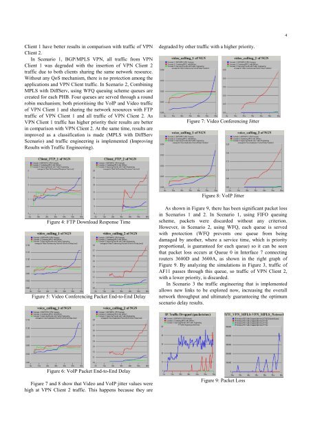
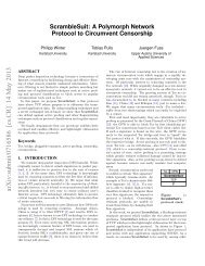
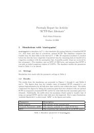
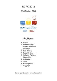
4Client 1 have better results <strong>in</strong> comparison with traffic of <strong>VPN</strong>Client 2.In Scenario 1, <strong>BGP</strong>/<strong>MPLS</strong> <strong>VPN</strong>, all traffic from <strong>VPN</strong>Client 1 was degraded with the <strong>in</strong>sertion of <strong>VPN</strong> Client 2traffic due to both clients shar<strong>in</strong>g the same network resource.Without any <strong>QoS</strong> mechanism, there is no protection among theapplications and <strong>VPN</strong> Client traffic. In Scenario 2, Comb<strong>in</strong><strong>in</strong>g<strong>MPLS</strong> with DiffServ, us<strong>in</strong>g WFQ queu<strong>in</strong>g scheme queues arecreated for each PHB. Four queues are served through a roundrob<strong>in</strong> mechanism; both prioritis<strong>in</strong>g the VoIP and Video trafficof <strong>VPN</strong> Client 1 and shar<strong>in</strong>g the network resources with FTPtraffic of <strong>VPN</strong> Client 1 and all traffic of <strong>VPN</strong> Client 2. As<strong>VPN</strong> Client 1 traffic has higher priority their results are better<strong>in</strong> comparison with <strong>VPN</strong> Client 2. At the same time, results areimproved as a classification is made (<strong>MPLS</strong> with DiffServScenario) and traffic eng<strong>in</strong>eer<strong>in</strong>g is implemented (Improv<strong>in</strong>gResults with Traffic Eng<strong>in</strong>eer<strong>in</strong>g).degraded by other traffic with a higher priority.Figure 7: Video Conferenc<strong>in</strong>g JitterFigure 8: VoIP JitterFigure 4: FTP Download Response TimeFigure 5: Video Conferenc<strong>in</strong>g Packet End-to-End DelayAs shown <strong>in</strong> Figure 9, there has been significant packet loss<strong>in</strong> Scenarios 1 and 2. In Scenario 1, us<strong>in</strong>g FIFO queu<strong>in</strong>gscheme, packets were discarded without any criterion.However, <strong>in</strong> Scenario 2, us<strong>in</strong>g WFQ, each queue is servedwith protection (WFQ prevents one queue from be<strong>in</strong>gdamaged by another, where a service time, which is priorityproportional, is guaranteed for each queue) so it can be seenthat packet loss occurs at Queue 0 <strong>in</strong> Interface 7 connect<strong>in</strong>grouters 3600D and 3600A, as shown <strong>in</strong> the right graph ofFigure 9. By analyz<strong>in</strong>g the simulations <strong>in</strong> Figure 3, traffic ofAF11 passes through this queue, so traffic of <strong>VPN</strong> Client 2,with a lower priority, is discarded.In Scenario 3 the traffic eng<strong>in</strong>eer<strong>in</strong>g that is implementedallows new l<strong>in</strong>ks to be explored now, <strong>in</strong>creas<strong>in</strong>g the overallnetwork throughput and ultimately guarantee<strong>in</strong>g the optimumscenario delay results.Figure 6: VoIP Packet End-to-End DelayFigure 7 and 8 show that Video and VoIP jitter values werehigh at <strong>VPN</strong> Client 2 traffic. This happens because they areFigure 9: Packet Loss
5VI. CONCLUSIONThe <strong>in</strong>teroperation of <strong>MPLS</strong> and DiffServ has manybenefits, ma<strong>in</strong>ly when Traffic Eng<strong>in</strong>eer<strong>in</strong>g is implemented.One benefit is the possibility of provid<strong>in</strong>g end-to-end <strong>QoS</strong>through different network doma<strong>in</strong>s. Used with DiffServ,<strong>MPLS</strong> can apply traffic differentiation, mapp<strong>in</strong>g the DSCP<strong>in</strong>to the EXP field from <strong>MPLS</strong> header.The ma<strong>in</strong> benefit of <strong>MPLS</strong> is to provide traffic eng<strong>in</strong>eer<strong>in</strong>gand resource reservation. In Scenario 3, Improv<strong>in</strong>g Resultswith Traffic Eng<strong>in</strong>eer<strong>in</strong>g, the <strong>VPN</strong> Client 2 traffic wasestablished <strong>in</strong> a different path from the shortest path chosen bythe conventional rout<strong>in</strong>g protocol. Us<strong>in</strong>g alternatives paths, theuse of network resources can be optimized and the traffic loadcan be distributed over many paths. The applicationperformance can thus <strong>in</strong>crease, be<strong>in</strong>g forwarded over a pathwith reserved resources.By comb<strong>in</strong><strong>in</strong>g <strong>MPLS</strong> with DiffServ, advantages can be<strong>in</strong>creased further. <strong>VPN</strong> Clients traffic can be forwardedthrough a pre-determ<strong>in</strong>ed path with resource reservation.Otherwise, if congestion is present, the complementarytechnique of DiffServ can be used to give priority to thecritical applications.Notice that the most difficult task is to identify which arethe most critical applications and to def<strong>in</strong>e which service classmust be assigned to each application. In this paper VoIP andVideo of <strong>VPN</strong> Client 1 were considered the most importantapplications due to their real time requirements and clientnecessity. In a congestion situation they received a bettertreatment from the network guarantee<strong>in</strong>g short delay and jitter.On the other hand, results show that the less priority classeswith fewer resources reserved do not improve the read<strong>in</strong>gs.[13] J. Boyle, V. Gill, A. Hannan, D. Cooper, D. Awduche, B. Christian:“Applicability Statement for Traffic Eng<strong>in</strong>eer<strong>in</strong>g with <strong>MPLS</strong>”, RFC3346, August 2002.VII. REFERENCES[1] E. C. Rosen and Y. Rekhter, “<strong>BGP</strong>/<strong>MPLS</strong> IP <strong>VPN</strong>s”, draft-ietf-l3vpnrfc2547bis-01.txt,September 2003.[2] J. Zeng and N. Ansari, “Toward IP Virtual Private Network Quality ofService: A Service Provider Perspective”, IEEE CommunicationsMagaz<strong>in</strong>e, pp. 113-119, Apr. 2003.[3] Y. Rekhter and T. Li: “A Border Gateway Protocol 4 (<strong>BGP</strong>-4)”,RFC1771, March 1995.[4] P. Zhang and R. Kantola, “Build<strong>in</strong>g <strong>MPLS</strong> <strong>VPN</strong>s with <strong>QoS</strong> Rout<strong>in</strong>gCapability”, Interwork<strong>in</strong>g 2000, pp. 292-301, 2000.[5] H. Lee, J. Hwang, B. Kang and K. Jun, “End-To-End <strong>QoS</strong> Architecturefor <strong>VPN</strong>s: <strong>MPLS</strong> <strong>VPN</strong> Deployment <strong>in</strong> a Backbone Network” presentedat International Workshop on Parallel Process<strong>in</strong>g, Toronto, Canada,2000.[6] T. Bates, Y. Rekhter, R. Chandra, D. Katz: “Multiprotocol Extensionsfor <strong>BGP</strong>-4”, RFC2858, June 2000.[7] F. L. Faucheur, B. Davie, S. Davari, P. Vaananen: “<strong>MPLS</strong> Support ofDifferentiated Services”, RFC 3270, May 2002.[8] S. Blake, D. Black, M. Carlson, E. Davies: “ An Architecture forDifferentiated Services”. RFC 2475, December 1998.[9] R. Prabagaran and J. B. Evans, “Experience with Class of Service (CoS)Translations <strong>in</strong> IP/<strong>MPLS</strong> Networks”, presented at 26th Annual IEEEConference on Local Computer Networks (LCN 2001), November 2001,Tampa, Florida, USA.[10] E. Rosen, A. Viswanathan, R. Callon: “Multiprotocol Label Switch<strong>in</strong>gArchitecture”, RFC3031, January 2001.[11] B. Jamoussi, L. Andersson, R. Callon and R. Dantu: “Constra<strong>in</strong>t-BasedLSP Setup us<strong>in</strong>g LDP”, RFC3212, January 2002.[12] D. Awduche, L. Berger, T. Li, V. Sr<strong>in</strong>ivasan and G. Swallow: “RSVP-TE: Extensions to RSVP for LSP Tunnels”, RFC3209, December 2001.