198937 SSK Stiffened INSTALLATION INSTRUCTIONS.pdf - Westeel
198937 SSK Stiffened INSTALLATION INSTRUCTIONS.pdf - Westeel
198937 SSK Stiffened INSTALLATION INSTRUCTIONS.pdf - Westeel
- No tags were found...

Create successful ePaper yourself
Turn your PDF publications into a flip-book with our unique Google optimized e-Paper software.
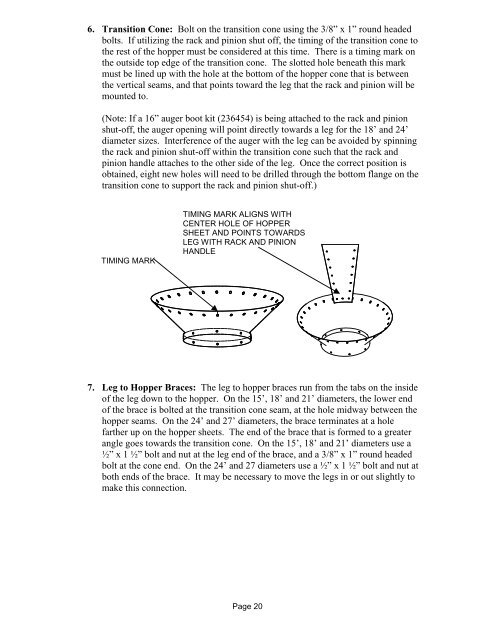
6. Transition Cone: Bolt on the transition cone using the 3/8” x 1” round headedbolts. If utilizing the rack and pinion shut off, the timing of the transition cone tothe rest of the hopper must be considered at this time. There is a timing mark onthe outside top edge of the transition cone. The slotted hole beneath this markmust be lined up with the hole at the bottom of the hopper cone that is betweenthe vertical seams, and that points toward the leg that the rack and pinion will bemounted to.(Note: If a 16” auger boot kit (236454) is being attached to the rack and pinionshut-off, the auger opening will point directly towards a leg for the 18’ and 24’diameter sizes. Interference of the auger with the leg can be avoided by spinningthe rack and pinion shut-off within the transition cone such that the rack andpinion handle attaches to the other side of the leg. Once the correct position isobtained, eight new holes will need to be drilled through the bottom flange on thetransition cone to support the rack and pinion shut-off.)TIMING MARKTIMING MARK ALIGNS WITHCENTER HOLE OF HOPPERSHEET AND POINTS TOWARDSLEG WITH RACK AND PINIONHANDLE7. Leg to Hopper Braces: The leg to hopper braces run from the tabs on the insideof the leg down to the hopper. On the 15’, 18’ and 21’ diameters, the lower endof the brace is bolted at the transition cone seam, at the hole midway between thehopper seams. On the 24’ and 27’ diameters, the brace terminates at a holefarther up on the hopper sheets. The end of the brace that is formed to a greaterangle goes towards the transition cone. On the 15’, 18’ and 21’ diameters use a½” x 1 ½” bolt and nut at the leg end of the brace, and a 3/8” x 1” round headedbolt at the cone end. On the 24’ and 27 diameters use a ½” x 1 ½” bolt and nut atboth ends of the brace. It may be necessary to move the legs in or out slightly tomake this connection.Page 20