
Create successful ePaper yourself
Turn your PDF publications into a flip-book with our unique Google optimized e-Paper software.
Part Number: 194940Revision: 1Date: June, 2010CONSTRUCTION GUIDE54' to105' <strong>GRAIN</strong> <strong>BIN</strong>
NEW IN THIS MANUAL• Modified "Warranty" section• Added "Cutting Openings" page• Modified "Wall Sheet & Bottom Angle" pagePage 2
LIMITED WARRANTY<strong>Westeel</strong> Division of Vicwest Operating Limited Partnership ("<strong>Westeel</strong>") warrants products that ithas manufactured and/or that are branded with its name (the "goods") subject to the followingterms and limitations, (the "warranty"):1. Duration of Warranty. The duration of the warranty is limited as follows:Galvanized BinsEasyCheckEasyFlowEasyAerFloorsSeedStor-K ConesPaintStructuralSeedStor ConesPaintStructuralRetro/Econo ConesStructuralPaintSmooth Wall BinsPaintStructural12 months12 months24 months12 months12 months12 months30 months30 months10 years12 monthsno warranty30 months10 yearsThe duration of the warranty will run from the date of purchase from a dealer or distributorauthorized by <strong>Westeel</strong> (the "warranty period").2. Limitation of Remedies Replacement. Within the warranty period, <strong>Westeel</strong> will replacethe goods and/or original manufactured components thereof which are found, to <strong>Westeel</strong>'ssatisfaction, to be defective. <strong>Westeel</strong> is not responsible for direct, indirect, special,consequential, or any other damages of any kind, including personal injury to anyindividual, howsoever caused, including caused by transportation of the goods for repairor replacement3. Procedure for Obtaining Service. In the event of a warranty claim, the purchaser mustcomplete any and all information required by <strong>Westeel</strong> in order to properly assess orinvestigate the claim. <strong>Westeel</strong> will not be responsible for the removal of any of the goodsfound to be defective, or transportation charges to and from <strong>Westeel</strong>'s authorized dealeror distributor, or for installation of any replacement goods and/or parts furnished under thewarranty.Page 3
Limitations as to Scope of Warranty. The warranty does not extend to defects or damagecaused, in whole or in part, by:i. use of a kind and/or to a degree not reasonably expected to be made of the goods;ii.iii.iv.improper storage of the goods both prior to and after purchase;damage caused by, or in the course of, installation or assembly;any use of the goods which is not an intended use as specified in <strong>Westeel</strong>'spublished product literature, or otherwise specified by <strong>Westeel</strong> in writing;v. any equipment attached to or used in conjunction with the goods;vi.vii.viii.ix.any field modifications or substitutions to original bin components;inadequate ventilation or any other circumstance not in keeping with propermaintenance and/or use of the goods;Acts of God, accident, neglect or abuse of the goods by the purchaser and/or anyother individual or entity; orAny use or installation inconsistent with <strong>Westeel</strong>’s Standard Disclaimers.4. Limitations as to Manufacturer. The warranty does not cover products sold by <strong>Westeel</strong>that are not manufactured by <strong>Westeel</strong>. In those circumstances, the purchaser is referredto the manufacturer of those products.6. Limitation of Implied Warranties and Other Remedies. To the extent allowed by law,neither <strong>Westeel</strong> nor its dealers, nor any company affiliated with <strong>Westeel</strong> makes anywarranties, representations, or promises as to the quality, performance, or freedom fromdefect of any Product covered by this Warranty.WESTEEL HEREBY DISCLAIMS, TO THE EXTENT APPLICABLE, ANY AND ALLIMPLIED WARRANTIES OF MERCHANTABILITY AND FITNESS FOR A PARTICULARPURPOSE. A PURCHASER’S ONLY REMEDIES IN CONNECTION WITH THISWARRANTY ARE THOSE SET FORTH IN THIS WARRANTY. IN NO EVENT WILLWESTEEL, ITS DEALERS, OR ANY COMPANY AFFILIATED WITH WESTEEL BELIABLE FOR INCIDENTIAL, CONSEQUENTIAL OR PUNITIVE DAMAGES.Some jurisdictions do not allow waivers of certain warranties, so the above waivers maynot apply to you. In that event, any implied warranties are limited in duration to ninety(90) days from delivery of the products. You may also have other rights which vary fromjurisdiction to jurisdiction.7. Exclusive Warranty. This warranty is the only warranty provided by <strong>Westeel</strong> and allother warranties and/or commitments, whether express or implied and no matter by whommade, statutory or otherwise, are subsumed and replaced by it and are of no legal effect.If any provision of the warranty is held by a court of competent jurisdiction to be void orunenforceable, in whole or in part, such provision shall be deemed severable and will notaffect or impair the legal validity of any other provision of the warranty.Page 4
DISCLAIMERSFoundation DesignThe foundations for the stiffened bin models are based on 4000 lbs. per sq. ft. (192 kPa) soilbearing capacity. All foundation designs use 3000 lbs. per sq. in. (21 MPa) ultimate compressivestrength (after 28 days) for concrete and 43,500 lbs. per sq. in. (300 MPa) re-bar. The foundationdesigns included in this manual are suggestions only, and will vary according to local soilconditions. <strong>Westeel</strong> will not assume any liability for results arising from their use.IMPORTANT:Foundation should be uniform and level. Level should notvary by more than ¼" over a span of four feet under thebottom ring angle. Any variance from level must be shimmedunder upright base assembly. If being utilized to support a full flooraeration system, this levelness requirement should extend acrossthe complete floor area.Method of ErectionThe recommendations for erecting <strong>Westeel</strong> Grain Bins should be closely followed to achieve thefull strength of the bin and to achieve adequate weather sealing. Warranty is void if therecommendations are not followed including but not limited to:1. Wall sheets and/or uprights, which are not specified for a given tier, are used.2. Foundations are found to be inadequate or out-of-level.3. Anchor bolts (cast-in-place, drill-in, chemical type or other) are found to be inadequate.4. Off-center loading or unloading is used. This does not apply to the use of approved sideunloading systems.5. Materials stored are not free-flowing or have a compacted bulk density greater than 55lbs/ft 3 (880 kg/m 3 ).If using Bin Jacks: Always lift on an upright. Choose a hoist with a suitable capacity for theexpected empty bin deadload. Make sure the rated capacity of the hoist is notexceeded.These <strong>Westeel</strong> Grain Bins are designed for:Design1. Non-corrosive, free-flowing materials up to 55 lbs/ft 3 (880 kg/m 3 ) average compacted bulkdensity.2. Maximum horizontal gusted wind speed of 94 mph (151 km/h).3. Seismic zone 2a (U.B.C. 1997).4. 15.0 lbs/ft 2 (.72 kPa) roof snow load.24.0 lbs/ft 2 (1.15 kPa) roof snow load when the optional roof stiffening rings are installed.5. 4000 lbs. (17.8 kN) evenly distributed on peak ring for 15’ – 24’ bins.5000 lbs. (22.2 kN) evenly distributed on peak ring for 27’ – 48’ bins.Page 5
Site and AssemblyUnless otherwise specifically provided in writing, <strong>Westeel</strong> does not take responsibility for anydefects or damages to any property, or injury to any persons, arising from or related to any site orassembly considerations, including but not limited to:• Bin location and bin siting;• Soil conditions and corresponding foundation requirements (note that the examplesprovided in manuals are for specifically stated soil conditions);• Bin assembly (<strong>Westeel</strong> recommends the use of qualified bin installers; contact<strong>Westeel</strong> for information on installers in your area);• Field modifications or equipment additions that affect the bin structure; and• Interconnections with neighbouring structures.• Compliance with all applicable safety standards, including but not limited to fallrestraint systems (ladders or other systems). Local safety authorities should becontacted as standards vary between jurisdictions.Critical Assembly Requirements1. Local code and jurisdictional requirements that are applicable to the grain bin installationmust be adhered to.2. Foundations must be designed for the loads being imparted to them, and for local soilconditions. <strong>Westeel</strong> foundation guidelines are for a set of stated conditions and may notbe applicable to local conditions.3. A foundation must provide uniform and level support to the grain bin structure beingsupported. Surface imperfections causing gapping must be remedied. This may involve,but not be limited to - grouting under the bottom ring of a non-stiffened bin, and shimmingunder the uprights of a stiffened bin or under the legs of a hopper.4. If extending an existing bin, ensure that the foundation is adequate for the increased loadsthat will be subjected to it.5. If installing an existing bin on a hopper, ensure that the bin is designed for a hopperapplication, and that the foundation is capable of withstanding the substantial point loadsthat the hopper legs apply. If uprights are present, ensure that they are supported.6. Ensure that the proper hardware is utilized for all bolted connections. Refer to the‘Hardware “Where Used” Chart’ in the Installation Manual. If a shortage occurs do notsubstitute. Take the necessary steps to obtain the proper hardware. Ensure nuts aretightened to the required torque values as provided in the Installation Manual.7. Refer to the appropriate Installation Manual to ensure a safe, proper structure, inparticular but not exclusively for the wall sheet and upright layouts. Do not deviate fromthe layouts provided.8. Ensure that an integral end-to-end connection exists between mating uprights.Successive uprights must not overlap.Page 6
9. Vertical tolerances between uprights and wall sheets are tight. This can be affected by“jacking” techniques, which can allow the tolerance to grow or shrink depending on thetechnique used. The gapping between successive uprights must be monitored to ensurethat upright holes align with bin sheet holes.10. When installing roof stiffening rings, and if it is necessary to shorten the stiffening ringtubes, shorten them as little as possible. Initially the nuts on the expanders should becentered and as close together as possible. When tightening, share the amount of takeupbetween expanders such that the nuts remain centered, and the amount ofengagement between all expanders on the same ring is equalized.11. Before anchoring the bin to the foundation, ensure that the bin is round. The maximumvariation from perfect roundness is 3/4" on the radius (see details in "wall sheet andbottom angle " section of manual). Locate anchor bolts towards the outside of the anchorbolt holes (away from bin) to permit the incremental expansion that can occur with theinitial filling.Grain Bin Use1. Do not off-center unload a grain bin. It is imperative to unload from the center of the binfirst, until as much grain as possible has been removed, and only then proceed to unloadfrom the next closest unload gate to the center. Continue utilizing the unload gates insuccession from the center towards the outside. Gate control mechanisms should beclearly marked and interconnected to prevent an external gate from being opened first.2. The only exception to center unloading is when a properly designed and installed sidedraw system is utilized. However, as bins tend to go out of round when employing sidedraws, the bin must be completely emptied before refilling.3. When unloading a bin with a mobile auger through a properly designed auger chute, theentry end of the auger should be pushed into the center of the bin before the auger isengaged. Slower rates of flow are preferable and should not exceed the capacity of an 8”auger.4. Ensure that the inner door panels of grain bin doors are completely closed and latchedbefore filling the grain bin.5. Never enter a loaded grain bin for any reason. Grain can be a killer.Rust on Galvanized PartsProduct Storage1. White rust forms when moisture is allowed to collect on galvanized surfaces that have yet todevelop the durable zinc oxide layer. This zinc oxide layer naturally occurs as the surfaceinteracts with carbon dioxide, and is characterized over time by the dull grey appearance thatweathered galvanized surfaces get.2. Parts that are not well ventilated or well drained can collect water between surfaces anddevelop white rust.3. White rust is not a structural concern if its development is stopped in the early stages. Alight film or powdery residue can occur after a period of heavy rainfall or a short time ofimproper storage. If white rust has started to develop, separate parts and wipe off anymoisture. Next, using a clean cloth, apply a thin layer of petroleum jelly or food-grade oilto the entire part.Page 7
4. If moisture is left on parts, this white rust can become more aggressive and turn into redrust. Red rust can cause degradation in the material and become a structural concern.Any parts that have red rust should be replaced immediately.Storage Guidelines1. Keep all bundles dry before assembly of thebin. Start assembly as soon as possible. Do notlay bundles on the bare ground, raise all bundles6” – 8” off the ground on wood blocks or timbers.Store curved wall sheets ‘hump-up’. All otherbundles material should be placed so that they arewell sloped to promote good drainage.2. Roof sheets must be elevated at least 12” at thesmall end of the sheets.3. Temporary storage can be provided by erectinga simple framework supporting a waterproof tarp.4. All bin boxes, ladder boxes and hardware boxes should be stored inside. These are notwaterproof, and will deteriorate in normal weather conditions, allowing moisture to contactthe parts inside.If Parts Become Wet1. If goods become submerged or wet, thebundles should be opened as soon as possible,sheets or material separated and dried. Keepseparated until assembly. Brace goodsproperly so as to avoid damage or injury frommaterial falling when in storage.2. Any boxed goods that become wet should be dried and stored in a new box that is free ofmoisture.3. In addition to wiping down wallsheets, a food-grade oil can also be applied with a clean,lint-free cloth. This will assist in preventing any further moisture from contacting thegalvanizing on the steel. Due to safety concerns with installation and use, <strong>Westeel</strong> doesnot recommend the use of oil on other parts such as roof sheets and safety ladders.Page 8
IMPORTANT NOTES1. In order to maintain your wall sheets in good condition separate sheets and allow aircirculation between them. Store sheets in a dry place. Do not store sheets with sheetends pointing upwards.2. To keep an even pressure on walls, the bin must always be unloaded from the centre.3. Contact local power officials for minimum power line clearance.4. See "Disclaimers - Design" for materials which can be stored.5. Tighten all bolts to the recommended torque setting (see Recommended Bolt Torquestable in Appendix).6. Do not locate grain bin close to high buildings, which might cause snow to fall onto orbuild up on the roof of the grain bin. Consider future expansion and allow space forloading and unloading of the bin. Your dealer and local government agriculturalconsultants can help you plan your storage system for maximum efficiency.Shortages and Damaged Parts;Report damaged parts or shortages immediately to the delivering carrier, followed by aconfirming letter requesting inspection by the carrier, if required. Order any replacement partsimmediately to ensure that assembly will not be held up by missing parts. All parts will becharged for and credit will be issued by party at fault - no credit will be issued if freight bill aresigned as received in good condition.Order Optional Equipment;Optional equipment such as unloading augers, aeration equipment, anchor bolts, foundationsealant, external ladders, safety cage and platforms, etc., should all be on site and checkedbefore assembly starts. Plan your installation in advance. For details, see assemblyinstructions supplied with optional equipment.List of Warning Decals;236564236088Consistent with <strong>Westeel</strong> Limited’s policy of continued research and development of ourproducts, we reserve the right to modify or change information contained in this publicationwithout notice.Page 9
Instructions For cutting Openings in <strong>Westeel</strong> Wide Corr Grain BinsA. General Rules for Cutting openings1. Never cut any uprights, roof ribs, or wall sheet bolted vertical seams to create an opening;2. Openings shall be located so equipment being installed won't interfere with any bin components/accessories;3. Openings shall be minimized as much as possible for structural integrity of grain bins;4. Corners in openings shall be cut with minimum radius of 1/8" to reduce stress concentration;5. Openings shall be sealed all the way around for all weather conditions;6. Instructions shall be followed closely to avoid damage to bin structure;7. Except cutting openings described below, any other modification to <strong>Westeel</strong> bins shall be approved by aprofessional engineer.B. Openings for Fan Transitions of Aeration Floors1. Consult aeration floor installation instructions for information on Planning floor layout;2. Openings shall be centered to a wall sheet in horizontal direction;3. Opening shall be cut as tight as it can be for the transition to go through;and shall have no more than 1/4" gap on any side to the section of a fan transition going through a bin wall;4. Opening height for fan transition shall be limited to 12.5" inches from bottom edge of a bottom wall sheet;5. Opening width shall not exceed 46.5" for stiffened bins and 72.5" for unstiffened bins;6. Vertical support shall be required to support load above opening;7. Bottom angles may be cut flush to the sides of an opening to form part of opening.C. Openings for Unloading Augers of Wide Corr Bins with Full Floor Aeration1. Consult aeration floor installation instructions for information on Planning floor layout;2. Openings shall be centered to a wall sheet in horizontal direction;3. Openings shall be cut as tight as it can be for unloading auger to go through andshall have no more than 1/4" gap to auger flange section on any side;4. Opening height for any auger shall be limited to 12.5" from the bottom edge of a bottom wall sheet;5. Vertical flange of a bottom angle may be cut flush to sides of an opening to form part of opening;D. Openings for Roof Vents in Roof Sheets1. Openings shall be centered between roof ribs and have 2.5" minimum distance between edge of opening and baseof a roof rib;2. Openings can be square, rectangular, or round;3. Openings shall be the same size as the inlet opening of a vent being installed;4. Any side of a square/rectangular opening shall have a maximum length of 18" and a circular opening shall have amaximum diameter of 24".Page 10
COMMERCIAL <strong>GRAIN</strong> <strong>BIN</strong> SPECIFICATIONS (54’ – 75’)MODEL<strong>BIN</strong>DIAMETERCAPACITY (a)EAVESHEIGHTOVERALLbu (b) m 3 Tonnes (c) ft m ft m540971990 2430 1953 33.2 10.11 48.5 14.805410 79000 2665 2143 36.8 11.23 52.2 15.915411 86020 2900 2333 40.5 12.34 55.9 17.035412 93030 3136 2523 44.2 13.46 59.5 18.155413 100040 3371 2714 47.8 14.58 63.2 19.275414 107060 3606 2904 51.5 15.70 66.9 20.385415 114070 3841 3094 55.2 16.81 70.5 21.5053’ 9”5416 121080 4077 3284 58.8 17.93 74.2 22.6216.37 m5417 128100 4312 3474 62.5 19.05 77.9 23.745418 135110 4547 3665 66.2 20.17 81.5 24.855419 142120 4783 3855 69.8 21.29 85.2 25.975420 149130 5018 4045 73.5 22.40 88.9 27.095421 156150 5253 4235 77.2 23.52 92.5 28.215422 163160 5488 4426 80.8 24.64 96.2 29.325423 170170 5724 4616 84.5 25.76 99.9 30.44600990070 3042 2443 33.2 10.11 50.3 15.326010 98720 3332 2678 36.8 11.23 53.9 16.446011 107380 3622 2913 40.5 12.34 57.6 17.566012 116040 3913 3147 44.2 13.46 61.3 18.676013 124700 4203 3382 47.8 14.58 64.9 19.796014 133360 4494 3617 51.5 15.70 68.6 20.916015 142020 4784 3852 55.2 16.81 72.3 22.0359’ 8”6016 150670 5075 4087 58.8 17.93 75.9 23.1418.19 m6017 159330 5365 4322 62.5 19.05 79.6 24.266018 167990 5656 4557 66.2 20.17 83.3 25.386019 176650 5946 4791 69.8 21.29 86.9 26.506020 185310 6237 5026 73.5 22.40 90.6 27.616021 193960 6527 5261 77.2 23.52 94.3 28.736022 202620 6818 5496 80.8 24.64 97.9 29.856023 211280 7108 5731 84.5 25.76 101.6 30.977209133120 4500 3611 33.2 10.11 53.7 16.377210 145590 4919 3949 36.8 11.23 57.4 17.497211 158060 5337 4287 40.5 12.34 61.1 18.617212 170520 5755 4625 44.2 13.46 64.7 19.737213 182990 6174 4963 47.8 14.58 68.4 20.847214 195460 6592 5302 51.5 15.70 72.1 21.967215 207930 7010 5640 55.2 16.81 75.7 23.0871’ 7”7216 220400 7428 5978 58.8 17.93 79.4 24.2021.83 m7217 232860 7847 6316 62.5 19.05 83.1 25.317218 245330 8265 6654 66.2 20.17 86.7 26.437219 257800 8683 6993 69.8 21.29 90.4 27.557220 270270 9102 7331 73.5 22.40 94.1 28.677221 282740 9520 7669 77.2 23.52 97.7 29.787222 295200 9938 8007 80.8 24.64 101.4 30.907223 307670 10356 8345 84.5 25.76 105.1 32.027509145370 4916 3943 33.2 10.11 54.6 16.637510 158900 5370 4310 36.8 11.23 58.2 17.757511 172430 5824 4677 40.5 12.34 61.9 18.877512 185960 6278 5044 44.2 13.46 65.6 19.997513 199490 6732 5411 47.8 14.58 69.2 21.107514 213020 7185 5778 51.5 15.70 72.9 22.227515 226540 7639 6145 55.2 16.81 76.6 23.3474’ 7”7516 240070 8093 6512 58.8 17.93 80.2 24.4622.74 m7517 253600 8547 6879 62.5 19.05 83.9 25.587518 267130 9001 7246 66.2 20.17 87.6 26.697519 280660 9455 7613 69.8 21.29 91.2 27.817520 294190 9909 7980 73.5 22.40 94.9 28.937521 307720 10362 8347 77.2 23.52 98.6 30.057522 321250 10816 8713 80.8 24.64 102.2 31.167523 334770 11270 9080 84.5 25.76 105.9 32.28Page 11
COMMERCIAL <strong>GRAIN</strong> <strong>BIN</strong> SPECIFICATIONS (78’ – 105’)MODEL<strong>BIN</strong>DIAMETERCAPACITY (a)EAVESHEIGHTOVERALLbu (b) m 3 Tonnes (c) ft m ft m7809158240 5353 4292 33.2 10.11 55.4 16.907810 172870 5844 4689 36.8 11.23 59.1 18.017811 187510 6334 5086 40.5 12.34 62.8 19.137812 202140 6825 5483 44.2 13.46 66.4 20.257813 216770 7316 5880 47.8 14.58 70.1 21.377814 231400 7807 6277 51.5 15.70 73.8 22.487815 246040 8298 6674 55.2 16.81 77.4 23.6077’ 7”7816 260670 8789 7070 58.8 17.93 81.1 24.7223.65 m7817 275300 9280 7467 62.5 19.05 84.8 25.847818 289930 9771 7864 66.2 20.17 88.4 26.957819 304570 10262 8261 69.8 21.29 92.1 28.077820 319200 10753 8658 73.5 22.40 95.8 29.197821 333830 11243 9055 77.2 23.52 99.4 30.317822 348460 11734 9452 80.8 24.64 103.1 31.427823 363100 12225 9849 84.5 25.76 106.8 32.549009216030 7315 5860 33.2 10.11 58.9 17.959010 235510 7968 6388 36.8 11.23 62.6 19.079011 254990 8622 6916 40.5 12.34 66.2 20.189012 274470 9275 7445 44.2 13.46 69.9 21.309013 293950 9929 7973 47.8 14.58 73.6 22.429014 313430 10583 8502 51.5 15.70 77.2 23.549015 332920 11236 9030 55.2 16.81 80.9 24.6589’ 6”9016 352400 11890 9558 58.8 17.93 84.6 25.7727.29 m9017 371880 12543 10087 62.5 19.05 88.2 26.899018 391360 13197 10615 66.2 20.17 91.9 28.019019 410840 13850 11144 69.8 21.29 95.6 29.129020 430320 14504 11672 73.5 22.40 99.2 30.249021 449800 15158 12200 77.2 23.52 102.9 31.369022 469280 15811 12729 80.8 24.64 106.6 32.489023 488760 16465 13257 84.5 25.76 110.2 33.5910509303150 10277 8223 33.2 10.11 63.2 19.2610510 329660 11167 8942 36.8 11.23 66.9 20.3810511 356180 12056 9661 40.5 12.34 70.5 21.4910512 382690 12946 10380 44.2 13.46 74.2 22.6110513 409210 13835 11099 47.8 14.58 77.9 23.7310514 435730 14725 11819 51.5 15.70 81.5 24.8510515 462240 15615 12538 55.2 16.81 85.2 25.96104’ 5”10516 488760 16504 13257 58.8 17.93 88.9 27.0831.83 m10517 515270 17394 13976 62.5 19.05 92.5 28.2010518 541790 18283 14696 66.2 20.17 96.2 29.3210519 568310 19173 15415 69.8 21.29 99.9 30.4310520 594820 20062 16134 73.5 22.40 103.5 31.5510521 621340 20952 16853 77.2 23.52 107.2 32.6710522 647850 21842 17572 80.8 24.64 110.9 33.7910523 674370 22731 18292 84.5 25.76 114.5 34.90(a) Capacity based on bin filled to ¾” below eaves line with 28º filling angle of repose(b) Based on 1.244 cu. ft. per bushel and 5% compaction below eaves line(c) Based on bulk density = 770kg/m 3 and 5% compaction below eaves linePage 12
ANCHOR BOLT RADIUS(Externally Stiffened Silos)1¼” (32 mm) DIA HOLEFOR ANCHOR BOLT“A”“D”ANCHOR BOLTRADIUS “R”“R”“C”“B”BASE PLATEPART NUMBER A B D232725 6” 9” 3”232726 8” 13” 5”232727 8” 13” 3”ANCHOR BOLT RADIUS“R”ANCHOR BOLT CHORD“C”<strong>BIN</strong> SERIESInch mm Inch mm5408 – 5422 325.5 8268 56.74 14415423 327.5 8319 57.09 14506008 – 6021 361.4 9178 56.71 14406022 – 6023 363.4 9229 57.02 14487208 – 7220 433.0 10998 56.64 14397221 – 7223 435.0 11049 56.90 14457508 – 7520 450.9 11453 56.62 14387521 – 7523 452.9 11504 56.88 14457808 – 7820 468.8 11908 56.61 14387821 – 7823 470.8 11958 56.85 14449008 – 9019 540.5 13727 56.58 14379020 – 9023 542.5 13778 56.78 144210508 – 10518 630.0 16002 56.53 143610519 – 10523 632.0 16053 56.71 1440No. ofANCHORBOLTS36404850526070Size of anchor bolts to be determined by a professional engineer responsible for the design/constructionof the foundation. Design loads of the grain silos are provided on the following 4 pages.For ‘special’ bins dimensions may vary due to optional equipment.Page 13
UPRIGHT LOADS - COMMERCIAL <strong>GRAIN</strong> <strong>BIN</strong>IMPERIALnon factored loads in kips ('000 pounds) per uprightBin Model 5409 5410 5411 5412 5413 5414 5415 5416 5417 5418 5419 5420 5421 5422 5423Vertical dead load 0.9 1.0 1.1 1.2 1.3 1.4 1.5 1.6 1.8 1.9 2.1 2.3 2.4 2.6 2.9Vertical grain load 28.9 34.3 40.0 46.1 52.4 59.1 66.1 73.4 80.9 88.7 96.7 105.0 113.5 122.2 139.0Vertical snow and peak load 3.6 3.6 3.6 3.6 3.6 3.6 3.6 3.6 3.6 3.6 3.6 3.6 3.6 3.6 3.6Vertical wind load 1.8 2.1 2.5 2.8 3.3 3.7 4.2 4.6 5.2 5.7 6.3 6.9 7.6 8.2 8.9Net vertical uplift load 0.9 1.2 1.4 1.7 2.0 2.3 2.6 3.0 3.4 3.8 4.2 4.7 5.2 5.6 6.0Horizontal Base shear 2.3 2.5 2.7 2.9 3.1 3.3 3.5 3.7 3.9 4.1 4.3 4.6 4.8 5.0 5.2Anchor bolts per base assy 1 1 1 1 1 1 1 1 1 1 1 1 1 1 2Bin Model 6009 6010 6011 6012 6013 6014 6015 6016 6017 6018 6019 6020 6021 6022 6023Vertical dead load 1.0 1.1 1.2 1.3 1.4 1.5 1.7 1.8 2.0 2.2 2.3 2.5 2.7 2.9 3.1Vertical grain load 30.2 35.7 41.6 47.9 54.6 61.5 68.8 76.4 84.3 92.4 100.8 109.5 118.4 127.5 136.9Vertical snow and peak load 3.9 3.9 3.9 3.9 3.9 3.9 3.9 3.9 3.9 3.9 3.9 3.9 3.9 3.9 3.9Vertical wind load 1.7 2.0 2.3 2.6 3.0 3.4 3.8 4.2 4.7 5.2 5.7 6.3 6.9 7.4 8.0Net vertical uplift load 0.7 0.9 1.1 1.3 1.6 1.8 2.1 2.4 2.7 3.1 3.4 3.8 4.2 4.5 5.0Horizontal Base shear 2.3 2.5 2.7 2.9 3.1 3.3 3.5 3.7 3.9 4.1 4.3 4.5 4.7 5.0 5.2Anchor bolts per base assy 1 1 1 1 1 1 1 1 1 1 1 1 1 2 2Bin Model 7209 7210 7211 7212 7213 7214 7215 7216 7217 7218 7219 7220 7221 7222 7223Vertical dead load 1.2 1.3 1.4 1.6 1.7 1.8 2.0 2.2 2.4 2.6 2.8 3.0 3.3 3.5 3.8Vertical grain load 32.5 38.4 44.7 51.4 58.5 65.9 73.7 81.8 90.2 99.0 108.1 117.4 127.1 137.0 147.2Vertical snow and peak load 4.5 4.5 4.5 4.5 4.5 4.5 4.5 4.5 4.5 4.5 4.5 4.5 4.5 4.5 4.5Vertical wind load 1.5 1.8 2.0 2.3 2.6 2.9 3.3 3.7 4.0 4.5 4.9 5.3 5.8 6.3 6.8Net vertical uplift load 0.3 0.5 0.6 0.7 0.9 1.1 1.2 1.5 1.6 1.8 2.1 2.3 2.5 2.8 3.0Horizontal Base shear 2.3 2.5 2.7 2.9 3.1 3.3 3.5 3.7 3.9 4.1 4.3 4.5 4.7 4.9 5.1Anchor bolts per base assy 1 1 1 1 1 1 1 1 1 1 1 1 2 2 2Bin Model 7509 7510 7511 7512 7513 7514 7515 7516 7517 7518 7519 7520 7521 7522 7523Vertical dead load 1.2 1.4 1.5 1.6 1.8 1.9 2.1 2.3 2.5 2.7 2.9 3.2 3.4 3.7 4.0Vertical grain load 33.1 39.1 45.5 52.2 59.4 66.9 74.8 83.1 91.6 100.5 109.8 119.3 129.1 139.2 149.5Vertical snow and peak load 4.6 4.6 4.6 4.6 4.6 4.6 4.6 4.6 4.6 4.6 4.6 4.6 4.6 4.6 4.6Vertical wind load 1.5 1.7 2.0 2.2 2.5 2.8 3.2 3.5 3.9 4.3 4.7 5.1 5.6 6.0 6.5Net vertical uplift load 0.2 0.4 0.5 0.6 0.8 0.9 1.1 1.2 1.4 1.6 1.8 2.0 2.1 2.4 2.6Horizontal Base shear 2.3 2.5 2.7 2.9 3.1 3.3 3.5 3.7 3.9 4.1 4.3 4.5 4.7 4.9 5.1Anchor bolts per base assy 1 1 1 1 1 1 1 1 1 1 1 1 2 2 2Bin Model 7809 7810 7811 7812 7813 7814 7815 7816 7817 7818 7819 7820 7821 7822 7823Vertical dead load 1.3 1.4 1.6 1.7 1.9 2.1 2.3 2.4 2.7 2.9 3.1 3.4 3.7 3.9 4.2Vertical grain load 33.7 39.7 46.2 53.0 60.3 67.9 75.9 84.3 93.0 102.0 111.4 121.0 131.0 141.3 151.8Vertical snow and peak load 4.8 4.8 4.8 4.8 4.8 4.8 4.8 4.8 4.8 4.8 4.8 4.8 4.8 4.8 4.8Vertical wind load 1.4 1.7 1.9 2.2 2.5 2.8 3.1 3.4 3.8 4.2 4.6 5.0 5.4 5.8 6.3Net vertical uplift load 0.1 0.2 0.3 0.4 0.6 0.7 0.8 1.0 1.1 1.3 1.4 1.6 1.7 1.9 2.1Horizontal Base shear 2.3 2.5 2.7 2.9 3.1 3.3 3.5 3.7 3.9 4.1 4.3 4.5 4.7 4.9 5.1Anchor bolts per base assy 1 1 1 1 1 1 1 1 1 1 1 1 2 2 2Design Notes:Above loads for <strong>Westeel</strong> Series 54-105 are based onMaximum peak load of 10,000 lbs evenly distributed on roof capSnow load of 24 pounds per square footDesign gusted wind velocity of 94 miles per hourBulk density of 55 lbs/ft3 [881 kg/M3]The above loads do not consider any seismic acceleration to the loads. In areas where seismic is a concern orparameters exceed the above stated parameters, contact <strong>Westeel</strong> Engineering.Page 14
UPRIGHT LOADS - COMMERCIAL <strong>GRAIN</strong> <strong>BIN</strong>IMPERIALnon factored loads in kips ('000 pounds) per uprightBin Model 9009 9010 9011 9012 9013 9014 9015 9016 9017 9018 9019 9020 9021 9022 9023Vertical dead load 1.5 1.7 1.8 2.0 2.2 2.4 2.6 2.9 3.1 3.4 3.6 4.0 4.2 4.6 4.8Vertical grain load 36.0 42.3 49.0 56.2 63.8 71.8 80.2 89.0 98.2 107.7 117.5 127.7 138.3 149.1 160.2Vertical snow and peak load 5.4 5.4 5.4 5.4 5.4 5.4 5.4 5.4 5.4 5.4 5.4 5.4 5.4 5.4 5.4Vertical wind load 1.3 1.5 1.8 2.0 2.2 2.5 2.8 3.1 3.4 3.7 4.0 4.4 4.8 5.1 5.5Net vertical uplift load -0.2 -0.1 -0.1 0.0 0.1 0.1 0.1 0.1 0.3 0.3 0.4 0.4 0.5 0.6 0.7Horizontal Base shear 2.3 2.5 2.7 2.9 3.1 3.3 3.5 3.7 3.9 4.0 4.2 4.4 4.6 4.8 5.0Anchor bolts per base assy 1 1 1 1 1 1 1 1 1 1 1 2 2 2 2Bin Model 10509 10510 10511 10512 10513 10514 10515 10516 10517 10518 10519 10520 10521 10522 10523Vertical dead load 1.8 2.0 2.2 2.4 2.7 2.9 3.2 3.4 3.8 4.0 4.4 4.7 5.1 5.4 5.8Vertical grain load 38.8 45.4 52.5 60.1 68.1 76.5 85.3 94.6 104.2 114.2 124.6 135.4 146.5 158.0 169.8Vertical snow and peak load 6.2 6.2 6.2 6.2 6.2 6.2 6.2 6.2 6.2 6.2 6.2 6.2 6.2 6.2 6.2Vertical wind load 1.3 1.4 1.6 1.8 2.0 2.2 2.5 2.7 3.0 3.3 3.6 3.9 4.2 4.5 4.8Net vertical uplift load -0.6 -0.6 -0.6 -0.6 -0.6 -0.7 -0.7 -0.7 -0.8 -0.8 -0.9 -0.9 -0.9 -0.9 -1.0Horizontal Base shear 2.4 2.5 2.7 2.9 3.1 3.3 3.5 3.6 3.8 4.0 4.2 4.4 4.6 4.7 4.9Anchor bolts per base assy 1 1 1 1 1 1 1 1 1 1 2 2 2 2 2Design Notes:Above loads for <strong>Westeel</strong> Series 54-105 are based onMaximum peak load of 10,000 lbs evenly distributed on roof capSnow load of 24 pounds per square footDesign gusted wind velocity of 94 miles per hourBulk density of 55 lbs/ft3 [881 kg/M3]The above loads do not consider any seismic acceleration to the loads. In areas where seismic is a concern orparameters exceed the above stated parameters, contact <strong>Westeel</strong> Engineering.Page 15
UPRIGHT LOADS - COMMERCIAL <strong>GRAIN</strong> <strong>BIN</strong>METRICnon factored loads in kN (KiloNewtons) per uprightBin Model 5409 5410 5411 5412 5413 5414 5415 5416 5417 5418 5419 5420 5421 5422 5423Vertical dead load 3.8 4.3 4.7 5.2 5.6 6.2 6.7 7.3 7.9 8.7 9.3 10.0 10.7 11.6 12.8Vertical grain load 128.8 152.5 177.9 204.9 233.2 263.0 294.1 326.4 359.9 394.6 430.3 467.0 504.8 543.4 618.2Vertical snow and peak load 16.1 16.1 16.1 16.1 16.1 16.1 16.1 16.1 16.1 16.1 16.1 16.1 16.1 16.1 16.1Vertical wind load 8.0 9.4 11.0 12.7 14.5 16.4 18.5 20.7 23.0 25.5 28.1 30.8 33.7 36.6 39.5Net vertical uplift load 4.2 5.2 6.3 7.5 8.9 10.2 11.7 13.4 15.1 16.8 18.8 20.8 22.9 25.1 26.8Horizontal Base shear 10.0 10.9 11.9 12.8 13.7 14.6 15.6 16.5 17.5 18.4 19.3 20.3 21.2 22.2 23.2Anchor bolts per base assy 1 1 1 1 1 1 1 1 1 1 1 1 1 1 2Bin Model 6009 6010 6011 6012 6013 6014 6015 6016 6017 6018 6019 6020 6021 6022 6023Vertical dead load 4.3 4.7 5.2 5.7 6.3 6.9 7.5 8.1 8.8 9.6 10.3 11.1 11.9 12.8 13.7Vertical grain load 134.2 158.9 185.2 213.2 242.7 273.6 306.0 339.7 374.8 411.0 448.5 487.0 526.6 567.3 608.9Vertical snow and peak load 17.3 17.3 17.3 17.3 17.3 17.3 17.3 17.3 17.3 17.3 17.3 17.3 17.3 17.3 17.3Vertical wind load 7.5 8.8 10.2 11.7 13.3 15.1 16.9 18.9 21.0 23.2 25.5 28.0 30.5 33.0 35.8Net vertical uplift load 3.2 4.0 4.9 5.9 7.0 8.2 9.4 10.8 12.2 13.6 15.2 16.9 18.6 20.2 22.0Horizontal Base shear 10.1 11.0 11.9 12.8 13.7 14.6 15.5 16.5 17.4 18.3 19.2 20.2 21.1 22.0 23.0Anchor bolts per base assy 1 1 1 1 1 1 1 1 1 1 1 1 1 2 2Bin Model 7209 7210 7211 7212 7213 7214 7215 7216 7217 7218 7219 7220 7221 7222 7223Vertical dead load 5.3 5.8 6.4 7.0 7.6 8.2 9.1 9.8 10.8 11.6 12.5 13.5 14.6 15.6 16.9Vertical grain load 144.8 170.9 198.9 228.6 260.0 293.1 327.7 363.8 401.4 440.4 480.8 522.4 565.3 609.4 654.7Vertical snow and peak load 20.0 20.0 20.0 20.0 20.0 20.0 20.0 20.0 20.0 20.0 20.0 20.0 20.0 20.0 20.0Vertical wind load 6.7 7.8 9.0 10.2 11.6 13.1 14.6 16.3 18.0 19.8 21.7 23.7 25.7 27.9 30.2Net vertical uplift load 1.4 2.0 2.6 3.3 4.0 4.8 5.5 6.5 7.2 8.2 9.2 10.3 11.1 12.3 13.3Horizontal Base shear 10.2 11.1 12.0 12.8 13.7 14.6 15.5 16.4 17.3 18.2 19.1 20.0 20.9 21.8 22.7Anchor bolts per base assy 1 1 1 1 1 1 1 1 1 1 1 1 2 2 2Bin Model 7509 7510 7511 7512 7513 7514 7515 7516 7517 7518 7519 7520 7521 7522 7523Vertical dead load 5.5 6.0 6.7 7.3 7.9 8.6 9.4 10.2 11.2 12.1 13.0 14.0 15.3 16.4 17.7Vertical grain load 147.4 173.8 202.2 232.3 264.2 297.7 332.8 369.5 407.6 447.2 488.2 530.5 574.2 619.0 665.1Vertical snow and peak load 20.6 20.6 20.6 20.6 20.6 20.6 20.6 20.6 20.6 20.6 20.6 20.6 20.6 20.6 20.6Vertical wind load 6.6 7.6 8.7 10.0 11.3 12.7 14.2 15.7 17.4 19.1 21.0 22.9 24.8 26.9 29.1Net vertical uplift load 1.1 1.6 2.1 2.7 3.4 4.1 4.7 5.6 6.2 7.1 7.9 8.9 9.5 10.5 11.4Horizontal Base shear 10.2 11.1 12.0 12.8 13.7 14.6 15.5 16.4 17.3 18.1 19.0 19.9 20.8 21.7 22.6Anchor bolts per base assy 1 1 1 1 1 1 1 1 1 1 1 1 2 2 2Bin Model 7809 7810 7811 7812 7813 7814 7815 7816 7817 7818 7819 7820 7821 7822 7823Vertical dead load 5.9 6.4 7.1 7.7 8.5 9.2 10.0 10.8 11.8 12.7 13.9 15.0 16.3 17.3 18.7Vertical grain load 149.9 176.7 205.4 236.0 268.2 302.2 337.8 375.0 413.7 453.9 495.5 538.4 582.7 628.3 675.2Vertical snow and peak load 21.3 21.3 21.3 21.3 21.3 21.3 21.3 21.3 21.3 21.3 21.3 21.3 21.3 21.3 21.3Vertical wind load 6.4 7.4 8.5 9.7 11.0 12.3 13.7 15.2 16.8 18.5 20.3 22.1 24.0 26.0 28.1Net vertical uplift load 0.5 1.0 1.4 2.0 2.5 3.1 3.7 4.5 5.0 5.8 6.4 7.2 7.7 8.7 9.4Horizontal Base shear 10.3 11.1 12.0 12.9 13.7 14.6 15.5 16.3 17.2 18.1 19.0 19.9 20.8 21.6 22.5Anchor bolts per base assy 1 1 1 1 1 1 1 1 1 1 1 1 2 2 2Design Notes:Above loads for <strong>Westeel</strong> Series 54-105 are based onMaximum peak load of 44.5 kN evenly distributed on roof capSnow load of 1.15 kPaDesign gusted wind velocity of 42.0 meters / secondBulk density of 881 kg/m3 [55 lbs/ft3]The above loads do not consider any seismic acceleration to the loads. In areas where seismic is a concern orparameters exceed the above stated parameters, contact <strong>Westeel</strong> Engineering.Page 16
UPRIGHT LOADS - COMMERCIAL <strong>GRAIN</strong> <strong>BIN</strong>METRICnon factored loads in kN (KiloNewtons) per uprightBin Model 9009 9010 9011 9012 9013 9014 9015 9016 9017 9018 9019 9020 9021 9022 9023Vertical dead load 6.7 7.5 8.1 8.9 9.7 10.8 11.7 13.0 13.9 15.1 16.2 17.7 18.7 20.3 21.5Vertical grain load 160.1 188.1 218.2 250.1 284.0 319.6 356.9 396.0 436.7 479.0 522.8 568.2 615.0 663.2 712.8Vertical snow and peak load 24.1 24.1 24.1 24.1 24.1 24.1 24.1 24.1 24.1 24.1 24.1 24.1 24.1 24.1 24.1Vertical wind load 6.0 6.9 7.8 8.8 9.9 11.1 12.3 13.6 15.0 16.5 18.0 19.5 21.1 22.9 24.7Net vertical uplift load -0.8 -0.6 -0.3 -0.1 0.2 0.3 0.6 0.7 1.1 1.3 1.8 1.8 2.4 2.6 3.1Horizontal Base shear 10.4 11.2 12.0 12.9 13.7 14.6 15.4 16.3 17.1 18.0 18.8 19.7 20.6 21.4 22.3Anchor bolts per base assy 1 1 1 1 1 1 1 1 1 1 1 2 2 2 2Bin Model 10509 10510 10511 10512 10513 10514 10515 10516 10517 10518 10519 10520 10521 10522 10523Vertical dead load 8.1 8.9 9.8 10.8 11.8 12.9 14.2 15.3 16.7 17.9 19.6 21.1 22.7 24.2 26.0Vertical grain load 172.6 202.2 233.7 267.3 302.9 340.3 379.6 420.7 463.5 508.1 554.4 602.3 651.7 702.7 755.3Vertical snow and peak load 27.7 27.7 27.7 27.7 27.7 27.7 27.7 27.7 27.7 27.7 27.7 27.7 27.7 27.7 27.7Vertical wind load 5.6 6.4 7.2 8.1 9.0 10.0 11.0 12.2 13.3 14.6 15.8 17.1 18.5 20.0 21.5Net vertical uplift load -2.5 -2.5 -2.7 -2.8 -2.8 -2.9 -3.2 -3.2 -3.4 -3.4 -3.8 -3.9 -4.2 -4.2 -4.5Horizontal Base shear 10.5 11.3 12.1 12.9 13.7 14.5 15.4 16.2 17.0 17.8 18.6 19.5 20.3 21.1 22.0Anchor bolts per base assy 1 1 1 1 1 1 1 1 1 1 2 2 2 2 2Design Notes:Above loads for <strong>Westeel</strong> Series 54-105 are based onMaximum peak load of 44.5 kN evenly distributed on roof capSnow load of 1.15 kPaDesign gusted wind velocity of 42.0 meters / secondBulk density of 881 kg/m3 [55 lbs/ft3]The above loads do not consider any seismic acceleration to the loads. In areas where seismic is a concern orparameters exceed the above stated parameters, contact <strong>Westeel</strong> Engineering.Page 17
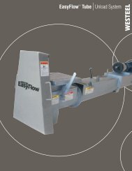
ROOF SYSTEMRoof Framing PlanCross BracingDetailRoof Peak DetailRafter SectionRafter number and locationvaries with bin diameterPage 18
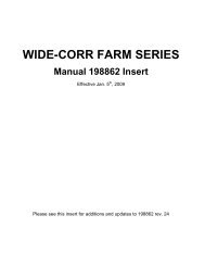
ROOF SYSTEM Cont.Rafter to StiffenerUpper to Lower RoofPurlin ConnectionBetween RaftersRafter toPurlin ConnectorRoof to WallConnectionPage 19
ROOF SYSTEM Cont.ElevationRoof/Center Clip DetailSection Through Roof CapWARNINGVERTICAL LOAD ON EYE BOLT OR TEMPERATURECABLE SUPPORT NOT TO EXCEED 1000 POUNDS.WESTEEL CAN ASSUME NO RESPONSIBILITY FORROOF OR WALL DAMAGE RESULTING FROMEXCESSIVE LOADS.Temperature Cable SupportWARNINGLOCATE TEMPERATURE CABLE AT LEAST 8FEET FROM THE CENTER OF <strong>GRAIN</strong> FLOW ORCENTER OF <strong>BIN</strong>.Page 20
WALL SHEET AND BOTTOM ANGLE ASSEMBLY3/8” x 1” BOLT TYPICAL FOR ALLHORIZONTAL AND VERTICAL SEAMSUNLESS OTHERWISE NOTED INHARDWARE “WHERE-USED” CHARTWALL SHEETCAULK ALONG VERTICAL SEAMAND 6” ALONG THE HORIZONTALSEAM (AS SHOWN)FLAT WASHER – CHECK“WHERE USED” CHARTBOTTOM ANGLEFOUNDATION SEALANT(NOT SUPPLIED)FOUNDATION SEALANT(NOT SUPPLIED)LOCATE BOTTOM ANGLE JOINTMIDWAY BETWEEN WALL SHEETVERTICAL SEAM. RING ANGLESBUTT TOGETHERCAULKCHECK “WHERE USED” CHARTAnchor bottom angle to concrete with 3/8" anchorbolts. Install one anchor bolt for every hole provided (6per bottom ring angle section).THICKNESSNOM (MIN)CENTURION WALL SHEET PART NUMBER MATRIXCORRUGATED WALL SHEETSGAUGELABELCOLOURWEIGHTlbsLENGTH(overall)Page 21PUNCHED WALL SHEETSFLAT REGULAR BOTTOM TOP.050 (.045) 18 Orange 72.8194696 194918 Stencil194680 194731 194771 194720.057 (.052) 17 Red 83.0 194681 194732 194772 194721.066 (.061) 15 Pink 97.7 194682 194733 194773 194722116.5”194692 194919 Stencil.076 (.070) 14 Lime 112.2194683 194734 194774 194723.096 (.088) 13 Green 141.1 194684 194735 194775 194724.116 (.107) 12 Blue 171.4 194685 194736 194776.126 (.117) 11 Purple 189.0194606 194737 194777.139 (.130) 10 Black 209.4 117.0” 194607 194738 194778.168 (.159) 8 Tan 252.1 194608 194739 194779LAMINATED WALL SHEETS – 7/16” BOLTS.096 (.088) 13 Green 141.7194604 194740 194745117.0”.116 (.107) 12 Blue 172.1 194605 194741 194746.126 (.117) 11 Purple 191.0194616 194742.139 (.130) 10 Black 211.6 118.25” 194617 194743.168 (.159) 8 Tan 254.8 194618 194744Bottom wall sheets (if supplied) are punched for full floor aeration flashing. Use bin boltsprovided to plug unused holes if a full floor aeration system is not being used.
<strong>BIN</strong> ROUNDNESSIt is imperative that the bin be as perfectly round as possible. The use of a string anchored and centeredon the concrete foundation to scribe a circle is required (see chart below for calculated radii. Theseradiuses are 3/4" smaller than the wall sheet radius at the bottom, so that the scribed circle can be seenduring assembly). A perfectly placed ring of sheets should be 3/4" on the outside of this line all the wayaround. This should be the first step in assembling a bin. The maximum amount that a bin can be out ofround is 3/4" on the radius, when measured from the center of the bin. In addition the wall sheets mustform a smooth circle with no flat or elongated portions. Before anchoring the bin to the foundation, ensureagain that the bin is round, within tolerance. Locate anchor bolts towards the outside of the anchor boltholes (away from bin) to permit the incremental expansion that can occur with the initial filling.NominalBin Dia.In feetScribe RadiusNominalBin Dia.In feetScribe RadiusNominalBin Dia.In feetScribe Radius15 7 ft 4.77 in. 33 16 ft 4.20 in. 60 29 ft 9.35 in.18 8 ft 10.68 in. 36 17 ft 10.11 in. 72 35 ft 8.97 in.21 10 ft 4.58 in. 39 19 ft 4.01 in. 75 37 ft 2.87 in.24 11 ft 10.49 in. 42 20 ft 9.92 in. 78 38 ft 8.78 in.27 13 ft 4.39 in. 48 23 ft 9.73 in. 90 44 ft 8.40 in.30 14 ft 10.30 in. 54 26 ft 9.54 in. 105 52 ft 1.92 in.WALL SHEET CAULKING DETAILInside view shown)IMPORTANT!ASSEMBLY DIRECTIONHORIZONTAL STRIPS OF CAULKINGARE USED TO SEAL GAP CAUSEDBY OVERLAP OF WALL SHEETS.LOCATE CAULKING AS SHOWN6”4”5/32” x 7/32” ROLLCAULKING (P/N) 193814APPLY AS SHOWN USING ACONTINUOUS STRIP4”6”SEE “WHERE USED” CHARTPage 22
COMMERCIAL <strong>BIN</strong> UPRIGHT ASSEMBLYIntroduction: The <strong>Westeel</strong> Commercial upright system consists of uprights and laminates. Single uprights, joinedby splice plates, are used at the top of bins. Laminate sections are introduced when vertical load requirementsdictate. Once introduced the laminates continue to be utilized for the balance of the assembly.A unique feature of the <strong>Westeel</strong> upright system is the progressive section. Not only do the uprights and laminatesincrease in gauge from the top to the bottom of the bin, they also increase in section.Progressive SectionsUPRIGHTS:5.5” 6.5” 10”LAMINATES:NOT ALL SECTIONS ARE USED ON ALL <strong>BIN</strong>SBoth upright and laminate sections measure 88” long. In the center of each there are vertical holes spaced at 2”centers. This permits use on both internally and externally stiffened bins. There are two locations on each wallsheet for attachment of the uprights. The wall sheet holes that mate with the uprights are spaced at 4” centers.Therefore only half of the center upright holes get used. Which set of holes depends on whether the bin is internallyor externally stiffened. The center holes not being used do not need to be filled with bolts. All other upright holesmust be filled with bolts.Upright/Laminate Identification: In order to properly erect the bin it is necessary to distinguish uprights fromlaminates, it is necessary to determine the gauge of the part, and it is necessary to determine the width of thesection. The various combinations are provided in the upright/ laminate table. It is also necessary to determine theorientation of the parts as there is a distinct top and bottom. All the information that is required for erection iscontained on the label.The label, is the easiest means of identification. It contains all of the necessary information. For assemblypurposes, the label is placed on the bottom of both uprights and laminates.Upright labels have solid colours and laminate labels are striped. For both uprights and laminates, the colourcorresponds with gauge and style (see table next page).Each upright and laminate has a unique identifying letter. This is prominently displayed on the label, andcorresponds with the respective assembly charts provided (see Upright/Laminate Graphic)SHADED FORUPRIGHTS. COLOURCORRESPONDS WITHGAUGE AND STYLE(SEE TABLE BELOW)UPRIGHTCIDENTIFYING LETTERPART NUMBERLAMINATEUSTRIPED SHADING FORLAMINATES. COLOURCORRESPONDS WITHGAUGE AND STYLE(SEE TABLE BELOW)232703CUPRIGHT CCDESCRIPTION232713ULAMINATE UUTHIS END DOWNMADE IN CANADAORIENTATIONTHIS END DOWNMADE IN CANADAPage 23
Upright/Laminate Assembly: Use the wall sheet/upright layout provided for the bin in question, to determine theproper order of the various upright and laminate components. The identifying letter on the label is the easiestmeans of identification. In addition to the identifying letter, every upright and laminate is also identified by gaugeand width. If for some reason the label is missing from a part, the following table contains information that will aid inthe identification of the various parts.Upright/Laminate IdentificationUprightsLaminatesBoxedIdentifyingWidth ofPart Number Description Gauge Label ColourLetterSection (in)S 232700S Upright S .076” Short 14 Light green 5.5”B 232702B Upright B .076” x 5.5” 14 Light green 5.5”C 232703C Upright C .116” x 5.5” 12 Blue 5.5”E 232705E Upright E .168” x 5.5” 8 Brown 5.5”F 232706F Upright F .168” x 6.5” 8 Silver 6.5”G 232707G Upright G .168” x 10” 8 Gold 10”U 232713U Laminate U .116” x 5.5” 12 Blue striped 5.5”W 232715W Laminate W .168” x 5.5” 8 Brown striped 5.5”X 232716X Laminate X .168” x 6.5” 8 Silver Striped 6.5”Y 232717Y Laminate Y .168” x 10” 8 Gold striped 10”J 232709J Upright Boxed J .168” x 10” 8 Red 10”K 232710K Laminate Boxed K .168” x 10” 8 Red Striped 10”L 232711L Laminate Boxed L .168” x 5.5” 8 Red Striped 5.5”NOT ALL SECTIONS ARE USED ON ALL <strong>BIN</strong> MODELSTOPUPRIGHTS LAMINATES BOXED UPRIGHTSS B C,E F G U,W X Y J K LBOTTOMPage 24
“J”, “K”, “L” AND 24” MAKE-UP 232779If more than one set of “J”, “K” and “L” boxed uprights are used (check wall sheet and upright layout), a 24” laminatemake-up section #232779 is inserted below the bottom “L” laminate. This allows easier access to connect anddisconnect the bin jack lifting lug to the uprights when boxed uprights are used. See base assembly diagram onprevious page for details on how the 24” make-up section is installed. When using the 24” make-up section#232779, note that the “L” laminate is offset 28” higher than the corresponding uprights instead of the normal 4”offset.Note: When using the 24” make-up section, some bolt holes on the “GY”, “JK” and “L” uprights do not line up.These holes do not need to field drilled. Where the “L” laminate overlaps the “GY” combination the top of the“L” laminate does not need to be bolted, as shown below.GYDOES NOTNEED TO BEBOLTED TO “GY”JKL20.0”J K L 232779JKLPage 25
Upright and Laminate Assembly: Uprights and laminates are designed to transfer vertical loads through an end to end, buttconnection. Ensure that mating uprights sit squarely on top of each other and do not overlap. Ensure that mating laminates sitsquarely on top of each other and do not overlap. Secure the joints with the nuts and bolts provided. Failure to do so can resultin structural failure.UPRIGHTSPLICE3/8” x 1”BOLTUP RIGHT4”LAMINATE3/8” NUTLOCATORHOLESCLALL BOLT HOLES INTHE UPRIGHT ANDLAMINATE FLANGESMUST BE FILLEDIn the assembly layouts, the combination of an upright and a laminate is called an assembly. For example, thecombination of a “C” upright and a “U” laminate would be called a “CU Assembly”. Both the “C” on the upright labeland the “U” on the laminate label, would remain visible, and would therefore remain distinguishable from other preassemblies.Base Assembly (for uprights laminate sections): At the bottom of an assembled bin that has laminates, therewill be a 4” gap between the bottom laminate and the base plate. It is imperative that this area is filled withthe 4” laminate section that protrudes from the base plate. In many cases this part can also be added to thebottom upright/laminate assembly during pre-assembly.UPRIGHTLAMINATE3/8” x 1” BOLTSHIMLAMINATED BASEPLATELAMINATEMAKE-UP PART3/8” NUTPage 26
Boxed Uprights: Special boxed uprights are located at the bottom of certain tall bins. They consist of a heavy 10”wide upright segment (J), a heavy 10” wide laminate section (K), and another 5.5” wide laminate section (L) that isused to form a box. The 10” wide segments (JK) can be pre-assembled as previously indicated. The remaining5.5” wide section (L) cannot be installed until after the JK pre-assembly has been bolted to the bin, the base platehas been positioned, and all of the center bolts tightened. The 5.5” wide section (L) can then be bolted to JK alongthe mating flange holes. L rests against the base plate. To prevent water from damming in the boxed section, installthe cap plate (232738) as shown.OUTER FLANGE HOLESCAN BE USED FORCL JPREASSEMBLY3/8” x 1½” BOLT3/8” NUTK“K” LAMINATEL“J” UPRIGHTCAP PLATE(232738)BOXED UPRIGHTBASE PLATE“L” UPRIGHT“L” LAMINATE“J” UPRIGHT“K” LAMINATEMAKE-UPLAMINATE2327793/8” x 1” BOLT‘X’ LAMINATE‘G’ UPRIGHTBASE PLATE – 2327273/8” NUTSHIM – 232730BOXED BASEPLATE3/8” NUT3/8” x 1” BOLTBASE PLATE ASSEMBLY8.5” x 14” – #900147SEISMIC BASEPLATEANCHOR BOLTHEAVY WASHERSHIM 8.5” x 14”– #900149Page 27
CRAWL DOOR ASSEMBLYFIELD DRILLING TO MATCH FOUR CORNER HOLESIN DOOR IS REQUIRED IN WALL SHEETS DIRECTLYABOVE AND BELOW DOORPLACE DOOR BEHIND THESHORT WALLSHEETSDOUBLE PUNCHEDSHORT WALLSHEET (194784)ONE TIERCRAWL DOOR (232958)NOTES:FOR EASIEST ASSEMBLY INSTALL ONE-TIER DOORBEFORE INSTALLING WALL SHEET IN TIER BELOW3 8 " x 1" BOLT, FLAT WASHER & NUTIMPORTANTINNER DOOR BOARD MUST BE CLOSED AND LATCHESCOMPLETELY ENGAGED BEFORE FILLING – FAILURE AND COLLAPSEOF <strong>BIN</strong> COULD RESULT IF <strong>BIN</strong> IS FILLED WITHOUT PROPERLYCLOSINGPage 28
interference with the splice. When progressing around the bin, this space between the end of the tubeand the next uprights may shrink with each additional tubethat is installed. On large diameter bins, if this space shrinksto the point where the wind ring splice interferes with theupright, then the tube will need to be cut. Make the cut suchthat the space that is created between the end of the tubeand the next upright is similar to the identical space on thefirst tube that was installed. In this manner, there will not bea shortage of tube.The final wind ring tube in a circle will need to be cut to length. Secure one end of the last tube in thepreviously installed wind ring splice as described above.Hold the tube in place and mark the cut-line relative to theAssembly Tip:previously installed tube at the other end. Insure thatWhen tightening wind ring clips, alwaysallowance is made for the 3/8” diameter bolt. Once the tubetighten in sequence starting at thehas been cut, install one end of the tube as describedspliced end of the tube, which hasabove. On the other end slide the wind ring splicealready been secured, and work towardscompletely onto the free end. Position this end relative tothe free, and as yet unspliced, end.the previously installed tube, and slide the splice onto thesecond tube until it is centered. Insert the centering bolt. Install all wind ring clips. Tighten all bolts.Internally Stiffened BinsAssembly Tip:When placing the first wind ring tube inplace, place one end close to an uprightwith a 8” to 10” overhang, and continuebuilding from that end. This will reducethe need for multiple cuts.The locations of the wind ring tubes for internally stiffened bins are identical to those for externallystiffened bins. See the “O”, as shown in the wall sheet and upright layout, located beside a horizontalwall sheet seam. The tubes are mounted to the outside of the bin. When assembling the internaluprights, bolt on the short wind ring bracket (same as upright splice 232720), such that it is just above thehorizontal seam as shown. These need to be mounted consistently around the bin at every uprightlocation. The actual installation of the wind ring tubes is identical to that described in the externallystiffened bin section above.HORIZONTALSEAMWIND RINGTUBE3/8” SPACERNUTSEALINGWASHERWIND RINGBRACKET3/8” x 1½”BOLT & NUTWIND RINGCLIPSEALINGWASHERINTERNALUPRIGHTWIND RINGCLIP3/8” x 1½”BOLTWIND RINGTUBEWIND RINGBRACKET3/8” NUTSPACER3/8” x 1½”BOLT & NUTPage 30
WIND RING ASSEMBLYWind rings fulfill their function when the bin is empty or partially filled. In high winds, the wind ringsprovide extra stiffness and help keep the bin round. Not all bins require wind rings. Bin diameter andheight determine the location and the quantity of wind rings required.Wind ring locations are identified by an “O” placed beside the relevant uprights within the wall sheet andupright layouts for the bin in question. At these locations wind ring tubes are secured to the uprightflanges with a series of clips that bolt into the upright locator holes that are located in the flanges ofthe 5.5” wide upright and upright/laminate combinations. Adjacent tubes are aligned and secured to eachother with wind ring splices. A 3/8” x 3¾” bolt through the splice keeps it centered on the connection.WALL SHEETUPRIGHTWIND RING CLIPPOSITION 1 ST SPLICE 8” TO10” FROM UPRIGHT ANDBUILD FROM THIS END INTHIS DIRECTIONWIND RINGSPLICEWIND RINGTUBEINSURE BUTT ENDS OF WINDRING TUBES ARE TIGHTAGAINST CENTERING BOLTCENTERING 3/8” x 3¾”BOLT AND NUTFIGURE 1Externally Stiffened BinsOnce the uprights have been secured to the bin walls, position thefirst wind ring tube and secure it to the upright using the wind ringclips provided. Two clips are required per upright, one on eachflange. Position the wind ring such that a wind ring splice (with boltinserted) can be slipped onto the end of the tube without interferingwith the upright or the wind ring clips. The splice should beorientated such that the bolt is horizontal.Insert the end of the next wind ring tube into the open end of thewind ring splice. Insure that the ends of both tubes are tightagainst the centering bolt. Secure the wind ring tube to theuprights with the wind ring clips. Continue around the bin.All wind ring splice connections should be made in the spacebetween uprights, and should not encroach into the area wherethe wind ring clips are securing the wind ring tube to the uprights.To avoid interference with uprights and the need to make multiplecuts, position an end of the first tube relatively close to an upright,such that the space between the end of the tube and the nextupright is maximized, and build from that end. Insure that both endsof the tube are far enough away from the closest uprights to avoid3/8” x 1½” BOLTFIGURE 2UPRIGHTWIND RINGTUBEWINDRINGCLIP3/8” NUTPage 29
PLANNING THE LOCATION OF LADDER COMPONENTSTiming of the positions of ladder, eaves rails, roof stairs or roof ladders, platforms and inside ladders, withrespect to each other, and other bin components is very important. Consideration of this must be given tothis during the planning stages before erection of the bin is initiated. The following are some points toconsider.Inside Ladders – The inside ladder sections bolt to existing holes in the horizontal seams of the wallsheets which are spaced at a consistent 9 3/8”. The inside ladders should also be centered on the roofpanel that contains the inspection hatch opening. Therefore this roof panel should be centered on thehorizontal wall sheet hole that is also the intended center of the inside ladder sections. Spinning the topring angles, and roof sheets, relative to this location on the wall sheets, may be required to achieveoptimum fit-up.Roof Stairs or Roof Ladders – The external ladder sections bolt to existing holes in the horizontalseams of the wall sheets. The roof stairs, or roof ladders, bolt to the ribs of roof panels. The roof stairs,or roof panels, are also positioned to the right, or left, of the inspection hatch. The latter should becentered on the inside ladders, if present. It may also be desirable to position the roof stairs, or roofladders, relative to some external elements such as overhead conveyors, or catwalks.Therefore the roof panel to which the roof stairs, or roof ladders, are bolted to, must be centered as muchas possible, to the center of the external ladder and eaves rails. Spinning the top ring angles, and roofsheets, relative to the wall sheets, to align this roof panel relative to the intended location of the externalladder may be required to achieve optimum fit-up.Uprights – Stiffened bins must be given additional consideration since the external ladder/platformcombinations must be mounted on either side of a stiffener location. On a stiffened wall sheet the uprightlocations can be identified by the line of vertical holes set in from either end (see page 14).Therefore, for fully featured bins containing external ladders, eaves rails, platforms, roof stairs or roofladders, and inside ladders, the following is an example of the timing considerations that should beundertaken prior to the construction of the bin.• Select the location of the various ladder components relative to external elements such asconveyors or catwalks.• Select the location of the various ladder components relative to other bin elements such as stencilsheets, door openings, remote vent opener, etc.• Determine the upright location that the external ladder sections and platforms will be centered on.During the initial assembly phases mark these locations on the top ring of wall sheets. For nonstiffenedbins this is not a consideration.• Determine if the inspection hatch is located on the right, or left side of the external laddersections.• Locate the top ring angles and roof panels relative to this position such that the roof panelcontaining the inspection hatch is centered, as much as possible, on the hole in the wall sheetthat depicts the center of the inside ladder sections. In general, the center of the inside laddersections should be 37 ½” (or 4 horizontal wall sheet spaces @ 9 3/8”) to the right or left of thecenter of the external ladder sections.• In the absence of an internal ladder, center the roof panel to which the roof stairs or roof laddersare being bolted to, to the center of the external ladder sections.Page 31
PLANNING THE LOCATION OF LADDER COMPONENTS (cont.)IF PRESENT, INSIDE LADDERSSHOULD BE CENTERED ON THEINSPECTION HATCHCENTER THE SIDEWALL LADDER ON THE ROOFLADDER, OR ROOF STAIRS, AS MUCH AS POSSIBLE.ON STIFFENED <strong>BIN</strong>S, THE POSITION OF THESIDEWALL LADDER RELATIVE TO THE UPRIGHTSCAN BE IMPORTANT (SEE BELOW). IT MAY BENECESSARY TO POSITION THE ROOF RELATIVE TOTHE UPRIGHTS WHEN INITIALLY ASSEMBLING TOAVOID INTERFERENCE WITH THE UPRIGHT.Rest PlatformLadder Cage(compatible with "passthrough rail" version)HIGHER MODELSSUPPORT ARM – P/N 234504 (6)PLASTIC CAP – P/N 234559SUPPORT ARM CLIPS– P/N 234517 (10)VERTICAL SUPPORT TUBE– P/N 234069PASS THROUGH RAILS – P/N 234505LOWER ARM– P/N 2341003/8” x 2½” BOLTS– P/N 150517INSPECTION HATCH CAGEAABLOCK-OFF PLATE(P/N 234530)LOWER MODELSPage 32
ROOF STAIR ASSEMBLYWall Ladder Assembly Considerations – When mated with a roof stairs, the wall ladders, cagesand eaves rails should be assembled as per the assembly instructions contained with those products.Z-Section SupportInspection HatchCage Assy.Roof Stair ModuleOutside LadderFor larger bin diameters, additional roof stair modules bolt together as shown in the assembly instructions.MATING HANDRAILSOVERLAP ATSUPPORT POSTLOCATIONS.ON LARGER COMMERCIALROOFS, THE HIGHER 7 ¼” Z –SECTIONS ARE USED BELOW THESTEP IN THE ROOF.Page 33
SPIRAL STAIRHandrailPlatformStair TreadsTube SupportsRest PlatformWall Brackets234144 - PLATFORM234154 - EAVES BRACKET234146 - BOTEaves BracketPage 34
AERATION ORIENTATIONON COMMERCIAL <strong>BIN</strong>SAeration details shown are for illustrative purposes only, and depend on bin model and fantransition selection. Contact WESTEEL engineering to provide drawings specific to yourrequirements.Page 35
Openings in Bin Wall SheetsGeneral Guidelines:• Any openings put in bin wall sheets should preferably be centered within the wall sheet in boththe horizontal and vertical directions. For a bin with uprights, the opening should occur betweenthe two uprights on the wall sheet in question. There should be no openings between an uprightand a vertical wall sheet seam. There can be no openings straddling a vertical or horizontal wallsheet seam. Do not cut uprights.• In some cases an opening can be off-center. Guidelines are provided.• Openings generally need to be reinforced. When a laminating sheet is required, preferably a fullsheet is utilized. A shorter sheet can be utilized, however at least 18” of laminating wall sheetmaterial must extend on either side of the penetration, and the holes used to attach thelaminating wall sheet to the base wall sheet must match that of the adjacent vertical seam. Atleast 1” of edge distance is required. If the laminating sheet crosses any stiffener holes, theseholes must be drilled out as well and filled with the required bolts.• Round holes are preferable. Square or rectangular holes are permitted, however the cut linesshould run horizontally and vertically (i.e. parallel to the edges of the wall sheet). Avoid sharpcorners. Rounded corners (1 ½” radius or greater) are preferred.• The following specific guidelines contain additional information. If the application in questiondoes not comply with these guidelines, consult with a <strong>Westeel</strong> Technical Sales Representatives.Specific Guidelines:• Small, round openings less than 4” (d ≤ 4”) in diameter are permitted without the need foradditional reinforcement. The edge of the opening must not be placed closer than 12” from ahorizontal or vertical wall sheet bolt seam.• Openings up to 17” (d ≤ 17”, h ≤ 17”) are permitted with a laminating sheet equal in gauge to thebase wall sheet. An edge distance of at least 8” to the nearest horizontal bolt seam and at least18” to the nearest vertical wall sheet bolt seam is required.• For larger openings up to 28” (d ≤ 28”, h ≤ 28”) consult the following table for the part number ofthe base wall sheet in question in order to determine the required laminating wall sheet.Openings must be centered vertically on the wall sheet and no closer than 18” to a vertical wallsheet bolt seam.• For openings greater than 28” (d > 28”, h > 28”) or for openings in laminated wall sheets, contacta <strong>Westeel</strong> Technical Sales Representative.• For aeration transition holes below a full floor aeration system, the opening must be centeredalong the length of the wall sheet, and between uprights. The transition must not interfere withuprights, and uprights cannot be cut or bent in any manner. The opening must be below theplane of the aeration floor and above the top edge of the bottom ring angle. Do not cut throughthe bottom ring angle. The transition must accommodate vertical load transfer.diameter
SIDEDRAW BAFFLE LOCATION DETAILSIMPORTANT:NOTE NOTE CORRECTORIENTATION OF OFBAFFLES (NARROWEND END OF OF OPENINGAT AT TOP) TOP)DISCHARGE IN THE 5 TH BOTTOM TIER(15’ 7” (4750mm) FROM TOP OF FOUNDATION)BAFFLE START POSTIONTIERS QTY BAFFLES"A"9 5 58”’ 1470mm10 6 70” 1770mm11 8 50” 1270mm12 9 62” 1570mm13 10 74” 1870mm14 12 54” 1370mm15 13 66” 1670mm16 14 78” 1970mm17 16 58” 1470mm18 17 70” 1770mm19 19 50” 1270mm20 20 62” 1570mm21 21 74” 1870mm22 23 54” 1370mm23 24 66”1670mmBAFFLE START POSTIONTIERS QTY BAFFLES"B”9 9 62”’ 1570mm10 10 74” 1870mm11 12 54” 1370mm12 13 66” 1670mm13 14 78” 1970mm14 16 58” 1470mm15 17 70” 1770mm16 19 50” 1270mm17 20 62” 1570mm18 21 74” 1870mm19 23 54” 1370mm20 24 66” 1670mm21 25 78” 1970mm22 27 58” 1470mm23 28 70” 1770mmDISCHARGE IN THE 2 ND BOTTOM TIER(4’ 7” (1400mm) FROM TOP OF FOUNDATION)BAFFLE SECTION<strong>BIN</strong> WALL SHEETFLANGED OUTLETRACK & PINION SLIDE GATESOME <strong>BIN</strong>S WITH SIDE DISCHARGE SYSTEMS MUSTHAVE EXTRA WIND RINGS INSTALLED. CONSULT <strong>BIN</strong>INSTALLATION MANUAL FOR LOCATION AND QUANTITYOF WIND RINGS.Side Draw ApplicationsIn certain situations there may be a desire to use a side draw system to unload the bin. In these cases special side draw flumes must be installed alongthe wall of the bin. This allows the commodity to be drawn from the top of the bin, reducing stresses on the bin wall. Because they draw from the side,they do not exert stresses which can cause the bin to go out of round. Bins with sidewall heights greater than 24' must have wind rings installed. This willprevent this from occurring. Please see your dealer for details.If the bin is installed with more than one sidewall draw system, only one may be used at a time.If a sidewall has been used, and not all of the commodity has been removed from the bin, the bin must still be unloaded from the centre bottom dischargeto ensure that the commodity reaches equal heights around the walls of the bin. Failure to do so will cause uneven wall stresses, which could cause thebin to go out-of-round. Bin failure could eventually occur.Side Draw ApplicationsIn certain situations there may be a desire to use a side draw system to unload the bin. In these cases special side draw flumes must be installed alongthe wall of the bin. This allows the commodity to be drawn from the top of the bin, reducing stresses on the bin wall. Because they draw from the side,they do not exert stresses which can cause the bin to go out of round. Bins with sidewall heights greater than 24' must have wind rings installed. This willprevent this from occurring. Please see your dealer for details.If the bin is installed with more than one sidewall draw system, only one may be used at a time.If a sidewall has been used, and not all of the commodity has been removed from the bin, the bin must still be unloaded from the centre bottom dischargeto ensure that the commodity reaches equal heights around the walls of the bin. Failure to do so will cause uneven wall stresses, which could cause thebin to go out-of-round. Bin failure could eventually occur.Page 37
450 Desautels, P.O. Box 792Winnipeg, Manitoba CANADA R3C 2N5Phone: 204-233-7133 Fax: 204-235-0796www.westeel.com<strong>Westeel</strong> Division Vicwest Operating Limited PartnershipPrinted in Canada