Mounting and Operating Instructions Shelter Lifting ... - haacon.de
Mounting and Operating Instructions Shelter Lifting ... - haacon.de
Mounting and Operating Instructions Shelter Lifting ... - haacon.de

Create successful ePaper yourself
Turn your PDF publications into a flip-book with our unique Google optimized e-Paper software.
<strong>haacon</strong> hilft heben<br />
<strong>Mounting</strong> <strong>and</strong> <strong>Operating</strong> <strong>Instructions</strong><br />
<strong>Shelter</strong> <strong>Lifting</strong>, Rolling <strong>and</strong> Loading System<br />
Type 1350.6,5.0.00 – 010<br />
Or<strong>de</strong>r no. 205270<br />
Certified in accordance with DIN EN ISO 9001<br />
Member of the DWT<br />
<strong>haacon</strong> hebetechnik gmbh<br />
Josef-Haamann-Str. 6<br />
D-97896 Freu<strong>de</strong>nberg/Main<br />
Tel.: +49 (0) 93 75/84-0<br />
Fax: +49 (0) 93 75/84-66<br />
e-mail: <strong>haacon</strong>@<strong>haacon</strong>.<strong>de</strong><br />
Internet: www.<strong>haacon</strong>.<strong>de</strong><br />
094103_f_gb_hrlsys_s <strong>haacon</strong> hebetechnik gmbh – Tel: +49 (0)9375 - 84-0 – Fax: +49 (0)9375 - 8466 1
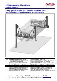
Content<br />
A. General Description of the system ....................................................4<br />
A.1 Description of the system .............................................................................................4<br />
A.2 Technical data .............................................................................................................5<br />
A.3 Technical information given on the system ..........................................6<br />
B. Basic structure of the system ..........................................................7<br />
B.1 Basic structure (narrow-track) ......................................................................................7<br />
B.1.1 Attaching the adaptors ................................................................................................7<br />
B.1.1.2 Fitting with mounting thread .........................................................................................7<br />
B.1.2 Attaching the outriggers ...............................................................................................8<br />
B.1.3 Attaching the racks ......................................................................................................8<br />
B.1.4 Attaching the castor unit ..............................................................................................9<br />
B.2 Changing from wi<strong>de</strong>- to narrow-track ............................................................................9<br />
B.3 Attaching ancillary equipment ..................................................................................... 10<br />
B.3.1 Drive shaft ................................................................................................................ 10<br />
B.3.2 Crank <strong>and</strong> crank h<strong>and</strong>le extension ............................................................................... 10<br />
B.3.3 Ergonomic crank ....................................................................................................... 11<br />
B.3.4 Rack <strong>and</strong> rack extension ............................................................................................ 11<br />
B.3.5 Locking unit for the racks ........................................................................................... 12<br />
B.3.6 Castor unit <strong>and</strong> wheels ............................................................................................... 12<br />
B.3.7 Tow bar ..................................................................................................................... 13<br />
B.3.8 Locking unit to prevent racks from running down .......................................................... 14<br />
B.3.9 Locking the castor units ............................................................................................. 14<br />
C. <strong>Operating</strong> the system .................................................................. 15<br />
C.1 Loading <strong>and</strong> unloading the vehicle .............................................................................. 15<br />
C.1.1 Unloading onto ground level ....................................................................................... 15<br />
C.1.2 Loading from ground level .......................................................................................... 15<br />
C.2 Loading <strong>and</strong> unloading an aircraft over a horizontal ramp .............................................. 16<br />
C.2.1 Loading over a horizontal ramp ................................................................................... 16<br />
C.2.2 Unloading over a horizontal ramp ................................................................................ 17<br />
C.3 Loading <strong>and</strong> unloading up <strong>and</strong> down an inclined ramp .................................................. 18<br />
C.3.1 Loading up an inclined ramp ....................................................................................... 18<br />
C.3.2 Unloading down an inclined ramp ................................................................................22<br />
094103_f_gb_hrlsys_s <strong>haacon</strong> hebetechnik gmbh – Tel: +49 (0)9375 - 84-0 – Fax: +49 (0)9375 - 8466 2
D. Components, maintenance <strong>and</strong> repair ............................................. 27<br />
D.1 List of components ....................................................................................................27<br />
D.2 Maintenance .............................................................................................................27<br />
D.3 On-the-spot trouble shooting .....................................................................................33<br />
D.4 Workshop repair ........................................................................................................33<br />
D.4.1 How to recognize wear <strong>and</strong> tear ..................................................................................33<br />
D.4.2 Repair ...................................................................................................................... 37<br />
D.4.3 List of necessary tools................................................................................................40<br />
D.6 Spare parts list .......................................................................................................... 41<br />
094103_f_gb_hrlsys_s <strong>haacon</strong> hebetechnik gmbh – Tel: +49 (0)9375 - 84-0 – Fax: +49 (0)9375 - 8466 3
Information regarding working safety<br />
Read <strong>and</strong> follow these mounting <strong>and</strong> operating instructions carefully before unpacking <strong>and</strong> operating the <strong>Lifting</strong>,<br />
Rolling <strong>and</strong> Loading System!<br />
Only people who know the mounting <strong>and</strong> operating instructions well <strong>and</strong> who have had corresponding training<br />
are allowed to assemble, use <strong>and</strong> repair the system.<br />
The <strong>Lifting</strong>, Rolling <strong>and</strong> Loading System may only be used for the operations ascribed to it. The operations ascribed<br />
to it are the loading <strong>and</strong> unloading of containers into <strong>and</strong> out of various types of aircraft, or the loading <strong>and</strong><br />
unloading up <strong>and</strong> down from a vehicle without additional equipment, resp.<br />
Before lifting, lowering or rolling the containers all safety installations <strong>and</strong> equipment have to be installed perfectly<br />
<strong>and</strong> it has to ensured that no one is st<strong>and</strong>ing in an endangered area.<br />
Attention!<br />
Do not fix anything with lashing straps on parts of the system!<br />
Inspection by an expert<br />
The lifting, rolling <strong>and</strong> loading system must be inspected by an expert <strong>de</strong>pending on the conditions un<strong>de</strong>r which<br />
it is used <strong>and</strong> the operational conditions, but at least once annually (annual operational safety inspection in accordance<br />
with the acci<strong>de</strong>nt prevention regulations BGV D8, Section 23, Paragraph 2).<br />
In all cases before the lifting, rolling <strong>and</strong> loading system is put back into operation, service the safety-relevant<br />
parts, e.g. the bar, gear unit, boom, rack <strong>and</strong> set of wheels.<br />
Experts are persons who, by virtue of their specialist training <strong>and</strong> experience, have sufficient knowledge in the<br />
field of winches, lifting units <strong>and</strong> towing units <strong>and</strong> who are familiar with the relevant national work safety regulations,<br />
acci<strong>de</strong>nt prevention regulations, directives <strong>and</strong> generally recognized technical regulations (e.g. DIN-EN<br />
st<strong>and</strong>ards) to the extent that they are able to assess the operational state of the lifting, rolling <strong>and</strong> loading system.<br />
Laws <strong>and</strong> regulations regarding the prevention of acci<strong>de</strong>nts have to be adhered to.<br />
Manufacturer’s <strong>and</strong> after sales service address:<br />
<strong>haacon</strong>-hebetechnik gmbh<br />
Josef-Haamann-Straße 6<br />
D-97896 Freu<strong>de</strong>nberg/Main<br />
Telefon (09375) 84-0<br />
Fax (09375) 8466<br />
When or<strong>de</strong>ring spare parts please quote:<br />
Type 1350.6,5.0.00 patents:<br />
Year of construction:<br />
Serial numbers:<br />
Reference (as per spare parts list):<br />
Number of spare parts required:<br />
A. General Description of the system<br />
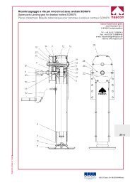
A.1 Description of the system<br />
S1200e on tow bar (centre piece).<br />
The <strong>Lifting</strong>, Rolling <strong>and</strong> Loading System 1350.6,5 will allow the loading <strong>and</strong> unloading of containers into <strong>and</strong> out<br />
of various types of aircraft <strong>and</strong> the loading <strong>and</strong> unloading of containers onto <strong>and</strong> down from vehicles without<br />
additional equipment.<br />
094103_f_gb_hrlsys_s <strong>haacon</strong> hebetechnik gmbh – Tel: +49 (0)9375 - 84-0 – Fax: +49 (0)9375 - 8466 4
The system has four corner posts attached to the container’s corner castings, which consists of adaptor with<br />
outrigger (gearbox) <strong>and</strong> castor unit. Each corner post will be actuated individually to level the container, a drive<br />
shaft will allow simultaneous actuation of two corner posts.<br />
The system can be used anywhere on firm <strong>and</strong> even surfaces with or without additional energy.<br />
Attention! Do not overload the system.<br />
Do not overload any component by operating the system incorrectly, e. g. excessive crankforce.<br />
A.2 Technical data<br />
Basic system<br />
<strong>Lifting</strong> capacity per set (4 jacks) 65 kN<br />
<strong>Lifting</strong> capacity per jack on ground plate 32,5 kN<br />
<strong>Lifting</strong> capacity per jack on wheels 21,5 kN<br />
<strong>Lifting</strong> stroke max. 1750 mm<br />
Slope max. 2°<br />
Crankforce per pair of jacks with crank h<strong>and</strong>le approx. 150 N<br />
Crankforce per pair of jacks with ergo. crank approx. 150 N<br />
Lift per crank turn approx. 4,3 mm<br />
Lift per turn of the ergonomic crank approx. 4,3 mm<br />
Operation range - 33 – + 50° C<br />
Weight (system <strong>and</strong> accessories) approx. 1082,0 kg<br />
Individual weights:<br />
Adapter* approx. 79,0 kg<br />
Outrigger <strong>and</strong> gearbox* approx. 36,0 kg<br />
Rack* approx. 41,0 kg<br />
Main pin approx. 1,5 kg<br />
castor unit* approx. 57,0 kg<br />
Crank h<strong>and</strong>le approx. 1,5 kg<br />
Crank extension approx. 1,0 kg<br />
Ergonomic crank approx. 6,0 kg<br />
Drive shaft* approx. 7,5 kg<br />
approx. 14,5 kg<br />
Tow bar* approx. 93,0 kg<br />
Ground plate approx. 6,0 kg<br />
Drag link approx. 5,0 kg<br />
Track rod approx. 7,0 kg<br />
Extension approx. 5,5 kg<br />
* These parts can be dissembled further.<br />
094103_f_gb_hrlsys_s <strong>haacon</strong> hebetechnik gmbh – Tel: +49 (0)9375 - 84-0 – Fax: +49 (0)9375 - 8466 5
A.3 Technical information given on the system<br />
There are stickers <strong>and</strong> plates on the system which must be adhered to in or<strong>de</strong>r to prevent acci<strong>de</strong>nts <strong>and</strong> damage<br />
to the system.<br />
094103_f_gb_hrlsys_s <strong>haacon</strong> hebetechnik gmbh – Tel: +49 (0)9375 - 84-0 – Fax: +49 (0)9375 - 8466 6
B. Basic structure of the system<br />
The operating instructions are based on the drawing no. 1350.6,5.0.00A in chapter C.<br />
B.1 Basic structure (narrow-track)<br />
Wi<strong>de</strong>-track is used for:<br />
loading <strong>and</strong> unloading a truck<br />
loading <strong>and</strong> unloading an aircraft over a horizontal<br />
ramp.<br />
B.1.1 Attaching the adaptors<br />
–<br />
–<br />
–<br />
–<br />
–<br />
–<br />
Adjust adaptor (1) to container height insert adaptor<br />
into the upper corner castings of the container.<br />
Take off the locking <strong>de</strong>vice (20) of the adaptor on<br />
the container long si<strong>de</strong> (push the attachment pin<br />
against its spring <strong>and</strong> turn until the securing pin is<br />
in a vertical position).<br />
Proce<strong>de</strong> the same way with the securing pin at the<br />
container front si<strong>de</strong> <strong>and</strong> also turn it into a vertical<br />
position.<br />
Insert the peg into the oval opening of the corner<br />
casting (if necessary lift the adaptor slightly), turn<br />
the securing pins into a horizontal position <strong>and</strong><br />
tighten the nut by h<strong>and</strong>.<br />
Insert the locking unit you have taken out into the<br />
oval opening of the adaptor <strong>and</strong> the corner casting<br />
<strong>and</strong> secure as <strong>de</strong>scribed.<br />
Tighten both nuts of the pins with a spanner / wrench<br />
belongs to the system <strong>and</strong> is supplied with it.<br />
B.1.1.2 Fitting with mounting thread<br />
(<strong>Operating</strong> <strong>Instructions</strong> 094047 enclosed)<br />
If the cabins are on the truck, use of the two-part<br />
mounting thread simplifies fitting / removal of the bars.<br />
094103_f_gb_hrlsys_s <strong>haacon</strong> hebetechnik gmbh – Tel: +49 (0)9375 - 84-0 – Fax: +49 (0)9375 - 8466 7
B.1.2 Attaching the outriggers<br />
– Turn the two clamps at the adaptor (1) until the<br />
eyes point away from the container long si<strong>de</strong>.<br />
–<br />
–<br />
–<br />
–<br />
–<br />
Insert pin (21) into the upper clamp (marked ‘W’)<br />
<strong>and</strong> secure it with a clip.<br />
St<strong>and</strong> outrigger (2) with its U-shaped opening (no<br />
gui<strong>de</strong> plates) in front of the container long si<strong>de</strong>.<br />
Take out the pins (22) facing towards the adaptor.<br />
Move the outrigger over the clamp eyes on the<br />
adaptor <strong>and</strong> fasten it with a pin.<br />
Secure the pin with a clip.<br />
B.1.3 Attaching the racks<br />
– Position the ground plate (9) below the opening of<br />
the outrigger (gearbox) (2).<br />
Attention!<br />
If a shelter is to be loa<strong>de</strong>d into the C-130 then the<br />
racks marked C-130 have to be attached so that<br />
they will enter the aircraft first.<br />
–<br />
–<br />
–<br />
–<br />
–<br />
St<strong>and</strong> each pair of racks (3) marked C-130 or C-141<br />
resp. in front of the adaptors (gearbox) already<br />
attached.<br />
Take off loose pins (4) of the outrigger.<br />
St<strong>and</strong> rack with its ball-shaped pin of the ground plate.<br />
(Teeth point upwards <strong>and</strong> towards the container).<br />
Move rack <strong>and</strong> ground plate over the U-shaped<br />
opening of the outrigger so that they are adjacent<br />
to the gui<strong>de</strong> plates.<br />
Secure rack with a pin (if necessary, attach crank<br />
h<strong>and</strong>le - h<strong>and</strong>ling as per B.3.2.). Engage pinion <strong>and</strong><br />
rack by turning the crank h<strong>and</strong>le until the second<br />
pin can be pushed through the eyes.<br />
094103_f_gb_hrlsys_s <strong>haacon</strong> hebetechnik gmbh – Tel: +49 (0)9375 - 84-0 – Fax: +49 (0)9375 - 8466 8
B.1.4 Attaching the castor unit<br />
– Attach drag link (10) at the castor unit (5) <strong>and</strong><br />
secure.<br />
–<br />
–<br />
–<br />
–<br />
–<br />
–<br />
–<br />
–<br />
Turn out the pin (23) at the lower end of the rack<br />
(3) (square opening, right-h<strong>and</strong>ed thread) with the<br />
crank h<strong>and</strong>le (6) <strong>and</strong> take it off.<br />
Attach extension (6a) to the crank h<strong>and</strong>le <strong>and</strong> insert<br />
into gearbox.<br />
Turn the rack up with the crank h<strong>and</strong>le until the castor<br />
unit can be rolled directly un<strong>de</strong>r the rack.<br />
Take off ground plate.<br />
Roll castor unit un<strong>de</strong>r the rack.<br />
Turn rack over the king pin (24) until approx. 2 mm<br />
½“ before the stop.<br />
Insert the pin with the exten<strong>de</strong>d crank h<strong>and</strong>le (6 +<br />
6b) into the lower end of the rack <strong>and</strong> tighten it. Pin<br />
must not project.<br />
Turn the crank h<strong>and</strong>le (52) <strong>and</strong> brake castor unit.<br />
Attention!<br />
Castor unit <strong>and</strong> e. g. outrigger must not jam when<br />
the rack is retracted <strong>and</strong> the container close to<br />
the ground. Refer to sticker ‘S1193e’ on the outrigger<br />
(gearbox).<br />
If this is not obeyed then the thrust pin (23) will<br />
be damaged <strong>and</strong> the castor unit can no longer be<br />
taken off. Rack <strong>and</strong> castor unit have to be exchanged.<br />
B.2 Changing from wi<strong>de</strong>- to narrow-track<br />
Narrow-track is used for:<br />
Rolling a container up or down the inclined aircraft ramp (<strong>de</strong>scribed in C.3.).<br />
Towing a container.<br />
Method:<br />
–<br />
–<br />
–<br />
–<br />
–<br />
–<br />
Basic structure as per B.1.<br />
Take load off the corner posts.<br />
Pull out the pin (21) at the upper of the two adjustable clamps (marked ‘W’).<br />
Turn the outrigger (gearbox) (2) with the rack (3) <strong>and</strong> castor unit (5) in front of the container front si<strong>de</strong> until a<br />
hole marked ‘N’ at the lower clamp matches the bore of the adaptor (1).<br />
Outrigger (gearbox) points away from the container long si<strong>de</strong> at approx. 60°.<br />
Insert pin into the lower bore of the clamp marked ‘N’ <strong>and</strong> secure with a clip.<br />
Repeat at the three other corner posts.<br />
094103_f_gb_hrlsys_s <strong>haacon</strong> hebetechnik gmbh – Tel: +49 (0)9375 - 84-0 – Fax: +49 (0)9375 - 8466 9
B.3 Attaching ancillary equipment<br />
B.3.1 Drive shaft<br />
The drive shaft (7) consists of two parts:<br />
(7a) Shorter part<br />
which ends on both si<strong>de</strong>s with an outer square. This<br />
shorter drive shaft is used for ‘narrow track’.<br />
(7b) Extension<br />
The extension <strong>and</strong> the shorter part together build a<br />
long shaft. This shaft is used for ‘wi<strong>de</strong> track’.<br />
– The drive shaft can be inserted into the inner<br />
square (of gearbox, ergonomic crank, drive shaft<br />
extension) by pushing or pulling the grooved sleeve<br />
(25) immediately behind the outer square. If necessary<br />
turn the inner square of the counterpart in<br />
or<strong>de</strong>r to adjust the drive shaft.<br />
– Check that the square drive ends engage properly<br />
whenever you operate the system.<br />
B.3.2 Crank <strong>and</strong> crank h<strong>and</strong>le extension<br />
The crank h<strong>and</strong>le (6) is used to assemble <strong>and</strong> dissemble<br />
the individual corner posts, to level the container,<br />
to attach the castor units (5) to the rack (3) <strong>and</strong> to extend<br />
<strong>and</strong> shorten the racks. It is recommen<strong>de</strong>d to use<br />
the ergonomic crank (6a) to bridge longer travels.<br />
The crank h<strong>and</strong>le can be attached or taken off by<br />
pushing the button (32) at the crank head. Release the<br />
button to lock.<br />
The h<strong>and</strong>le can be fol<strong>de</strong>d through 90º when the button<br />
(33) is pushed <strong>and</strong> the h<strong>and</strong>le is pulled at the same<br />
time.<br />
Ratcheting mechanism:<br />
� Lever (34) <strong>and</strong> crank are in a 90° angle:<br />
ratcheting in either direction.<br />
�<br />
Lever points to the right or to the left:<br />
ratcheting in one direction only.<br />
Use the extension when the castor unit is attached.<br />
094103_f_gb_hrlsys_s <strong>haacon</strong> hebetechnik gmbh – Tel: +49 (0)9375 - 84-0 – Fax: +49 (0)9375 - 8466 10
B.3.3 Ergonomic crank<br />
The ergonomic crank (6a) will enable the operator to<br />
crank with both h<strong>and</strong>s <strong>and</strong> to crank at a height most<br />
convient for him.<br />
Attachment:<br />
–<br />
–<br />
–<br />
–<br />
–<br />
–<br />
Hold ergonomic crank in a horizontal position.<br />
Crank (6) points away from the container.<br />
Insert crank’s square-shaped pin into the patterned<br />
disc of the outrigger (gearbox).<br />
Turn crank h<strong>and</strong>le slowly <strong>and</strong> thus let the outer<br />
square engage with the gearboxes inner square.<br />
Turn ergonomic crank upwards through 30°.<br />
Push the pin with the ball-shaped head at the<br />
ergonomic crank against its spring <strong>and</strong> hold, push<br />
ergonomic crank further into the gearbox until its<br />
locking mechanism is firmly behind the patterned<br />
disc.<br />
Turn ergonomic crank into the most convenient<br />
position. Release pin <strong>and</strong> thus arrest it.<br />
B.3.4 Rack <strong>and</strong> rack extension<br />
Use rack <strong>and</strong> rack extension (3) for loading <strong>and</strong> unloading<br />
trucks.<br />
Take off the extensions when loading <strong>and</strong> unloading<br />
aircraft only <strong>and</strong> attach the locking unit for<br />
the racks (B.5.).<br />
Attaching the rack extension:<br />
– Insert crank h<strong>and</strong>le into the inner tube of the<br />
extension <strong>and</strong> turn to the right against the spring<br />
pressure.<br />
Taking the rack extension off:<br />
– Insert crank h<strong>and</strong>le (6) into the inner square of the<br />
rack extension <strong>and</strong> turn to the left until the nut no<br />
longer engages.<br />
–<br />
Take crank h<strong>and</strong>le off <strong>and</strong> pull rack extension upwards.<br />
Attention!<br />
The racks have to be in line.<br />
Treat pegs <strong>and</strong> <strong>and</strong> bores with utmost care - do<br />
not damage them.<br />
094103_f_gb_hrlsys_s <strong>haacon</strong> hebetechnik gmbh – Tel: +49 (0)9375 - 84-0 – Fax: +49 (0)9375 - 8466 11<br />
3<br />
6
B.3.5 Locking unit for the racks<br />
Attention!<br />
Generally whenever the rack (3) is shortened, the<br />
end of the rack must be equipped with the locking<br />
unit stowed at the adaptor (1).<br />
– Take off the spring pin <strong>and</strong> the locking unit.<br />
–<br />
–<br />
Attach locking unit at the rack end (the pins of the<br />
locking unit have to disappear insi<strong>de</strong> the rack (3)<br />
completely).<br />
Tighten locking unit with the crank h<strong>and</strong>le (6) at the<br />
end of the rack.<br />
B.3.6 Castor unit <strong>and</strong> wheels<br />
The wheels of the castor units (5) can be taken off<br />
or attached individually for exchange or for stowage<br />
purposes.<br />
Taking them off:<br />
The castor has to be without load.<br />
– Loosen the nut (35) at the end of the axles as far<br />
as possible with a spanner/wrench (width across<br />
flats 24 mm) <strong>and</strong> turn it home until the securing pin<br />
(diam. approx. 0,63“) is parallel with the receptable.<br />
–<br />
Take wheel with hub <strong>and</strong> rim off the axle (36).<br />
All wheels have to be taken off <strong>and</strong> stowed in their<br />
stowage position above the outrigger before the jacks<br />
can be swung into their park position.<br />
094103_f_gb_hrlsys_s <strong>haacon</strong> hebetechnik gmbh – Tel: +49 (0)9375 - 84-0 – Fax: +49 (0)9375 - 8466 12<br />
6
B.3.7 Tow bar<br />
The tow bar (40) is used for steering while an aircraft is<br />
loa<strong>de</strong>d or unloa<strong>de</strong>d or for steering <strong>and</strong> towing a container<br />
outsi<strong>de</strong> the aircraft is only permitted in narrow<br />
track configuration.<br />
Narrow-track configuration<br />
– For basic structure refer to B.1. <strong>and</strong> B.2.<br />
– Both pins (37) at the triangular frame have to be<br />
pushed back. Lift the locker at the same time.<br />
– Attach the triangular frame (39) between two adaptors<br />
(1).<br />
– Lift the locker <strong>and</strong> insert pins into the bores of the<br />
adaptors.<br />
– Secure the pin by releasing the locker (38).<br />
– Attach center piece to the triangular frame, fasten<br />
with a pin (42) <strong>and</strong> secure with a clip.<br />
– Attach the castor drag link (10) at the strut (41) <strong>and</strong><br />
secure with a clip.<br />
Wi<strong>de</strong>-track configuration<br />
– For basic structure see B.1.<br />
– Push back both pins at the triangular frame <strong>and</strong> lift<br />
the spring locker at the same time.<br />
– Attach the triangular frame between two adaptors.<br />
– Lift the locker <strong>and</strong> push the pins into the bores of<br />
the adaptor.<br />
– Turn the triangular frame up towards the container<br />
wall.<br />
– Attach center piece with a pin at the lateral tube of<br />
the triangular frame <strong>and</strong> secure with a clip.<br />
– Insert extension (43) into the lateral tube <strong>and</strong> fasten<br />
with a pin (44). Secure with a clip.<br />
–<br />
Attach castor drag link (10) no. 1350.6,5.115.00<br />
(with pin) at the extension <strong>and</strong> secure with a clip.<br />
Attention!<br />
Moving the shelter in wi<strong>de</strong>-track configuration is<br />
only permitted for level loading <strong>and</strong> unloading of<br />
an aircraft <strong>and</strong> for movements of the container<br />
over short distances immediately near the aircraft<br />
in walking speed only.<br />
094103_f_gb_hrlsys_s <strong>haacon</strong> hebetechnik gmbh – Tel: +49 (0)9375 - 84-0 – Fax: +49 (0)9375 - 8466 13
B.3.8 Locking unit to prevent racks from<br />
running down<br />
To prevent the rack (3) from running down in its stowed<br />
position at the aircraft or on the truck a special locking<br />
unit (53) is inserted into the outrigger (gearbox).<br />
–<br />
–<br />
Push the button <strong>and</strong> take the locking unit out into<br />
the inner square of the gearbox while still pushing<br />
the button.<br />
Let the button go <strong>and</strong> check that the locking unit<br />
will not fall out (the locking unit is held back as long<br />
as the button is not pushed).<br />
B.3.9 Locking the castor units<br />
For various purposes <strong>de</strong>scribed in paragraph ‘C’ the<br />
swivelling castor units (5) have to be blocked.<br />
–<br />
–<br />
–<br />
–<br />
–<br />
Take out the square-shaped pin which is stowed at<br />
a clamp above the outrigger (gearbox).<br />
Turn the corner post into the position required <strong>and</strong><br />
secure.<br />
Turn the castor unit into travelling direction.<br />
Insert the square-shaped pin on the si<strong>de</strong> opposite<br />
the brakes parallel with the wheels into the square<br />
opening at the lower end of the rack. Push the bore<br />
of the retaining plate over the retaining pin of the<br />
king pin (24) at the castor.<br />
Secure the square-shaped pin with a spring clip.<br />
094103_f_gb_hrlsys_s <strong>haacon</strong> hebetechnik gmbh – Tel: +49 (0)9375 - 84-0 – Fax: +49 (0)9375 - 8466 14
C. <strong>Operating</strong> the system<br />
C.1 Loading <strong>and</strong> unloading the vehicle<br />
When loading or unloading a vehicle it has to st<strong>and</strong> on firm, even ground.<br />
The maximum inclination of the container is restricted to 2°.<br />
C.1.1 Unloading onto ground level<br />
– Basic configuration as per B.1.1. to B.1.3.<br />
–<br />
–<br />
–<br />
–<br />
Attention!<br />
Open twistlocks on the truck.<br />
Use crank h<strong>and</strong>le (6) to crank the container up by approx. 25 mm 1“.<br />
Insert drive shafts (7) (B.3.1.)<br />
Lift the container either with the crank h<strong>and</strong>le (6) or the ergonomic crank (6a) by approx. 100 mm 4“ <strong>and</strong> drive<br />
the truck away (there should be a second person to gui<strong>de</strong> the driver).<br />
Attention!<br />
Fouling the system with the vehicle might lead to the collapse of the system.<br />
Lower the container<br />
Attention!<br />
* Avoid oscillations of the container by e. g. corresponding cranking.<br />
* Watch all four corner posts. As soon as you reach the first mark for a motor-stop (refer to sticker<br />
S1193) stop the motors immediately.<br />
– Lower the container either crank h<strong>and</strong>le or ergonomic crank now.<br />
– Take off the drive shafts.<br />
– If necessary, take load off each corner post individually.<br />
– Only after load has been taken off all corner posts the whole system may be taken off the container.<br />
C.1.2 Loading from ground level<br />
– Basic configuration as per B.1.1. to B.1.3.<br />
– Use crank h<strong>and</strong>le (6) to crank the container up by approx. 25 mm 1“.<br />
– Insert drive shafts (7) <strong>and</strong> lift container by another 100 mm 4“. Level container.<br />
– Lift the container either with the crank h<strong>and</strong>le (6) or the ergonomic crank (6a) by approx. 100 mm 4“ above<br />
trucked level.<br />
– Drive the truck carefully un<strong>de</strong>r the container (there should be a second person to gui<strong>de</strong> the driver).<br />
–<br />
Position the truck twistlocks directly un<strong>de</strong>r the lower hole of the container’s corner castings.<br />
Attention!<br />
Correct only the position of the truck twistlocks, if they do not match the holes of the container’s corner<br />
castings. Do not move the system.<br />
094103_f_gb_hrlsys_s <strong>haacon</strong> hebetechnik gmbh – Tel: +49 (0)9375 - 84-0 – Fax: +49 (0)9375 - 8466 15
C.2 Loading <strong>and</strong> unloading an aircraft over a horizontal ramp<br />
C.2.1 Loading over a horizontal ramp<br />
Drive the truck with the container as closely to the ramp as possible <strong>and</strong> into the position a<strong>de</strong>quate for loading<br />
the aircraft.<br />
In or<strong>de</strong>r to unload the truck it has to be on even, firm ground. The maximum inclination of the container is restricted<br />
to 2°.<br />
For unloading the container refer to B.1.1. to B.1.4.<br />
–<br />
–<br />
–<br />
Attention!<br />
Open twistlocks on the truck.<br />
Use crank h<strong>and</strong>le (6) to crank the container up by approx. 25 mm 1“.<br />
Insert drive shafts (7) (B.3.1.).<br />
Lift the container either with the crank h<strong>and</strong>le (6) or the ergonomic crank (6a) by approx. 100 mm 4“ <strong>and</strong> drive<br />
the truck away (there should be a second person to gui<strong>de</strong> the driver).<br />
Attention!<br />
Fouling the system with the vehicle might lead to the collapse of the system.<br />
If the distance between the container <strong>and</strong> the ramp exceeds 4 m 13‘ then lower the container to a travelling<br />
height of approx. 460 mm 18‘.<br />
If the distance between the container <strong>and</strong> the ramp exceeds 10 m 30‘ then the system has to be changed<br />
into narrow track configuration. (B.2)<br />
– Take load off each corner post individually <strong>and</strong> turn castor units (5) into travelling direction. Pull parking brake<br />
(51 / 52).<br />
– Attach exten<strong>de</strong>d drive shaft (7).<br />
– Open parking brake.<br />
– Roll container up to approx. 600 mm 2‘ in front of the ramp <strong>and</strong> into a loading position.<br />
–<br />
–<br />
–<br />
–<br />
–<br />
–<br />
–<br />
–<br />
–<br />
–<br />
–<br />
–<br />
–<br />
Attention!<br />
To adjust the container position use the drag links (10) individually.<br />
Pull the parking brake (51).<br />
Attach ropes/chains to the front adaptor eyes (1) <strong>and</strong> connect them with the aircraft rope. Refer to drawing<br />
no. 180690.<br />
Shorten front racks (B.3.4.) <strong>and</strong> attach locking unit (B.3.5.).<br />
Lift the container above the level of the supported ramp by either crank h<strong>and</strong>le (6) or ergonomic crank (6a).<br />
Open parking brake (51).<br />
Push or pull the container into the aircraft as far as possible, so that the container <strong>and</strong> the system do not jam<br />
the aircraft but also roll over as many aircraft rollers as possible.<br />
Lower the container with either a rolling surface or a pallet un<strong>de</strong>rneath down onto the aircraft rollers of the<br />
ramp.<br />
Secure the container with the aircraft rope <strong>and</strong> by pulling the rear parking brakes (51 / 52).<br />
Take load off the front corner posts <strong>and</strong> take them off. The adaptors con stay on the container <strong>and</strong> can be<br />
used to tie down the container insi<strong>de</strong> the aircraft.<br />
Continue pulling the container into the aircraft. If necessary adjust the direction by steering the rear castors<br />
(5) with the track rods (11).<br />
Pull the container into the rear racks (3) are approx. 150 mm 6“ away from the ramp.<br />
Take load off the rear castors <strong>and</strong> take them off. The adaptors may stay on the container <strong>and</strong> can be used to<br />
tie down the container insi<strong>de</strong> the aircraft.<br />
Stow all parts you have taken off <strong>and</strong> all the parts used for steering the system insi<strong>de</strong> the aircraft.<br />
094103_f_gb_hrlsys_s <strong>haacon</strong> hebetechnik gmbh – Tel: +49 (0)9375 - 84-0 – Fax: +49 (0)9375 - 8466 16
–<br />
–<br />
Pull the container into its final position <strong>and</strong> tie it down.<br />
If necessary outrigger (gearbox) (2), racks <strong>and</strong> castor units (without wheels) can stay on the container. Swing<br />
outrigger (gearbox) into the position marked (P). The wheels are stowed at the clamp on the adaptor. Refer to<br />
3rd option <strong>de</strong>scribed later on.<br />
C.2.2 Unloading over a horizontal ramp<br />
Attention!<br />
Do not take the aircraft winch off before the container is well outsi<strong>de</strong> the aircraft <strong>and</strong> st<strong>and</strong>ing firmly on<br />
the system.<br />
–<br />
–<br />
–<br />
–<br />
–<br />
–<br />
–<br />
–<br />
–<br />
–<br />
–<br />
–<br />
–<br />
–<br />
–<br />
–<br />
–<br />
–<br />
Push or pull the container out of the aircraft until the front end projects the ramp by approx.250 mm 10“.<br />
Attach front corner posts according to B.1.1. to B.1.4.<br />
Turn castor units (5) into driving direction <strong>and</strong> attach track rod (11).<br />
Distribute the load evenly among all corner posts.<br />
Push or pull the container out until the rear end rests on the ramp by approx. 400 mm 16“. Use track rod for<br />
steering.<br />
Brake front caster units (51 / 52):<br />
Attach rear corner posts acc. to B.1.1. to B.1.4.. Use shorten racks (3) of the corresponding aircraft type (attach<br />
locking unit for the tack B.3.5.).<br />
Attach cross shaft (7).<br />
Lift container by approx. 25 mm<br />
Open parking brakes at the front corner posts.<br />
Pull container out of the aircraft completely until the distance between container <strong>and</strong> ramp is approx. 500 mm<br />
20“.<br />
Take off ropes / chains <strong>and</strong> aircraft rope.<br />
Brake all parking brakes for transporting the container with the truck.<br />
Extend the racks.<br />
Lift container slightly above trucked level.<br />
Drive truck un<strong>de</strong>r the container. There should be a second person to gui<strong>de</strong> this.<br />
Position the truck twistlocks directly un<strong>de</strong>r the lower openings of the container corner castings.<br />
Lower container until load is taken off four corner posts.<br />
Travelling with the container over longer distances<br />
–<br />
–<br />
–<br />
–<br />
–<br />
–<br />
–<br />
–<br />
–<br />
–<br />
–<br />
Brake all four castors.<br />
Extend all racks.<br />
Lower container down to approx. 500 mm 20“.<br />
Turn castor units to a 90° angle with the container long si<strong>de</strong>. Take off drive shafts. Take load off individual corner<br />
posts <strong>and</strong> swing castor units (5).<br />
Lower container to ground level <strong>and</strong> take load off the corner posts.<br />
Change corner posts from wi<strong>de</strong>- to narrow-track (B.2.).<br />
Turn castor units into travelling direction.<br />
Attach tow bar to front castor units (B.3.7.).<br />
Lock rear castor units so they will not swivel (B.3.9.).<br />
Lift container to a travelling height of approx. 460 mm 18“.<br />
Open all parking brakes (51 / 52). Container is now ready for rolling.<br />
094103_f_gb_hrlsys_s <strong>haacon</strong> hebetechnik gmbh – Tel: +49 (0)9375 - 84-0 – Fax: +49 (0)9375 - 8466 17
–<br />
–<br />
–<br />
Attention!<br />
Max. travelling speed (narrow-track only!)<br />
on even, hard surfaces 16 km/h 10 mph<br />
on even, smooth surfaces 8 km/h 5 mph<br />
on uneven surfaces 5 km/h 3,2 mph<br />
C.3 Loading <strong>and</strong> unloading up <strong>and</strong> down an inclined ramp<br />
C.3.1 Loading up an inclined ramp<br />
– Container is st<strong>and</strong>ing on the ground. Basic configuration as per B.1.1. to B.1.4. <strong>and</strong> B.2.<br />
– Lift container with the crank (6) by approx. 25 mm 1“.<br />
– Insert long drive shaft (7a) (B.3.1.)<br />
–<br />
Attach tow bar (8) to front adaptors (1) (B.3.7.). Turn the support wheel on the tow bar into travelling direction.<br />
(See sticker S’1185‘ on the towbar).<br />
Drawing no. 180690<br />
094103_f_gb_hrlsys_s <strong>haacon</strong> hebetechnik gmbh – Tel: +49 (0)9375 - 84-0 – Fax: +49 (0)9375 - 8466 18
–<br />
Attention!<br />
When loading the aircraft up the inclined ramp the tow bar must not be used to tow the container.<br />
Attach ropes / chains at the front adaptor eyes according to drawing no. 310189 <strong>and</strong> connect them with the<br />
aircraft rope.<br />
Attention!<br />
The angle of the ropes / winches must not exceed 40°, i. e. the distance between the attachment of the<br />
aircraft rope <strong>and</strong> adaptor (1) has to be at least 3.5 m 12‘. Refer to drawing no. 310189.<br />
–<br />
–<br />
–<br />
–<br />
To help with steering attach a rope of approx. 5 m 16‘ laterally through the eye of the tow bar so that it is possible<br />
to operate the tow bar on both si<strong>de</strong>s without st<strong>and</strong>ing the ramp.<br />
Open locking unit of the castor units (5).<br />
Connect castor track rod (10) <strong>and</strong> drag link (11).<br />
Attach four ramp extensions according to the position of the castor wheels.<br />
Attention!<br />
Make sure that when you roll up the inclined ramp the container is as horizontal as possible. Stop <strong>and</strong><br />
correct the height of each corner post several times to keep the container in a horizontal position.<br />
For safety reasons adjust the height of the container (on front <strong>and</strong> rear si<strong>de</strong>) only when the container is<br />
secured by the aircraft rope <strong>and</strong> cannot move. Keep the aircraft rope un<strong>de</strong>r tension. Put wedges behind<br />
all four rear wheels of the system. Do not st<strong>and</strong> on the ramp to do so.<br />
Make sure neither the container nor the system jam the aircraft. Watch especially the upper edge of<br />
the container <strong>and</strong> the container floor when leaving the inclined ramp <strong>and</strong> entering the aircraft.<br />
–<br />
–<br />
–<br />
Open all parking brakes (51 / 52).<br />
Pull container slowly towards the ramp. Steer with<br />
the tow bar in front (by pulling the rope on both<br />
si<strong>de</strong>s of the container) <strong>and</strong> the track rod at the rear<br />
so that the container is aligned to the cargohold.<br />
If the container has been aligned correctly when reaching<br />
the ramp, take tow bar <strong>and</strong> track rod off <strong>and</strong><br />
lock the rear castor units so they cannot swivel.<br />
If the container has to be aligned after reaching the<br />
ramp <strong>and</strong> while the container is entering the aircraft<br />
then the track rod stays on the rear corner posts.<br />
094103_f_gb_hrlsys_s <strong>haacon</strong> hebetechnik gmbh – Tel: +49 (0)9375 - 84-0 – Fax: +49 (0)9375 - 8466 19
Drawing no. 310189<br />
094103_f_gb_hrlsys_s <strong>haacon</strong> hebetechnik gmbh – Tel: +49 (0)9375 - 84-0 – Fax: +49 (0)9375 - 8466 20
Attention!<br />
When loading the aircraft up the inclined ramp no one is allowed behind the container.<br />
For safety reasons the personnel at the front end of the container has to walk along the outer edges of<br />
the ramp <strong>and</strong> later along the aircraft walls. The personnel at the rear end of the container has to walk<br />
alongsi<strong>de</strong> the container <strong>and</strong> later alongsi<strong>de</strong>, not on the ramp. Refer to drawing no. 310189.<br />
–<br />
–<br />
–<br />
–<br />
Lift container by approx. 100 mm 4“ in front <strong>and</strong> 200 mm 8“ at the rear.<br />
Pull container slowly <strong>and</strong> smoothly over the ramp extensions onto the aircraft ramp.<br />
Correct the rear castor units so that the container is properly aligned with the cargohold.<br />
Correct the height of the corner posts.<br />
When properly aligned:<br />
–<br />
–<br />
–<br />
–<br />
–<br />
Put wedges behind all four rear wheels.<br />
Take off track rod <strong>and</strong> drag link at rear.<br />
Lock rear castor units against swivelling <strong>and</strong>, if necessary move wedges to make room for this.<br />
Adjust height of rear end of the container (st<strong>and</strong>ing alongsi<strong>de</strong> the container not behind it) by using the crank<br />
h<strong>and</strong>le.<br />
Continue pulling the container into the aircraft while still adjusting the height of the container in or<strong>de</strong>r to avoid<br />
jamming the aircraft.<br />
Attention!<br />
Make sure that when you roll up the inclined ramp the container is as horizontal as possible. Stop <strong>and</strong><br />
correct the height of each corner post several times to keep the container in a horizontal position.<br />
For safety reasons adjust the height of the container (on front <strong>and</strong> rear si<strong>de</strong>) only when the container is<br />
secured by the aircraft rope <strong>and</strong> cannot move. Keep the aircraft rope un<strong>de</strong>r tension. Put wedges behind<br />
all four rear wheels of the system. Do not st<strong>and</strong> on the ramp to do so.<br />
Make sure that neither the container nor the system jam the aircraft. Watch especially the upper edge<br />
of the container <strong>and</strong> the container floor when leaving the inclined ramp <strong>and</strong> entering the aircraft.<br />
–<br />
–<br />
–<br />
–<br />
–<br />
–<br />
Pull container into the aircraft as far as possible while still steering at the front.<br />
Stop as soon as rope/chain touch the outrigger (gearbox).<br />
Position wedges behind the rear wheels which have entered the horizontal cargohold already. Pull parking<br />
brake.<br />
Take off ropes / chains, open parking brake <strong>and</strong> continue pushing the container insi<strong>de</strong> the aircraft.<br />
Take off the tow bar <strong>and</strong> steer each front corner post individually with the track rod until the container has<br />
reached its tie-down position.<br />
Pull parking brakes <strong>and</strong> lower container onto the floor.<br />
094103_f_gb_hrlsys_s <strong>haacon</strong> hebetechnik gmbh – Tel: +49 (0)9375 - 84-0 – Fax: +49 (0)9375 - 8466 21
Taking the system off, stowage <strong>and</strong> tying the container<br />
down<br />
Option 1<br />
– Take the corner posts off, except for the adaptors.<br />
– Adaptors stay on the container.<br />
– Stow all the parts you have taken off insi<strong>de</strong> the<br />
aircraft.<br />
– Tie the container down.<br />
Option 2<br />
– Take off the whole system <strong>and</strong> stow it insi<strong>de</strong> the<br />
aircraft.<br />
– Tie the container down.<br />
Option 3<br />
– Turn the corner posts into their stowage position at<br />
the front si<strong>de</strong> of the container (projection approx.<br />
480 mm 19“).<br />
– Take off the drive shafts <strong>and</strong> the tow bar.<br />
– Take off <strong>and</strong> stow the wheels (B.3.6.).<br />
– Crank the crank shafts (51) of the castor unit parallel<br />
with the container walls.<br />
– Take off the cranks (52), turn through 180° <strong>and</strong> insert<br />
above the square of the drive shaft. Secure.<br />
– Turn corner posts with outriggers (gearbox), racks<br />
<strong>and</strong> castor units (without wheels) in front of the<br />
container front si<strong>de</strong> until the holes marked ‘P’ at the<br />
lower clamp match the bores of the adaptors. The<br />
brakes (51) point away from the container wall.<br />
– Insert pin (21) into the lower bore marked ‘P’ <strong>and</strong><br />
secure.<br />
– Attach locking units at the outrigger (gearbox)<br />
(B.3.8.).<br />
– Tie the container down.<br />
– Stow the parts you have taken off insi<strong>de</strong> the aircraft.<br />
C.3.2 Unloading down an inclined ramp<br />
The system is stowed on the container. If not, refer to<br />
B.1.1. to B.1.4. <strong>and</strong> B.2.<br />
– Take off ropes tying the container to the aircraft.<br />
– Pull the pin (21) out of the hole marked ‘P’ at the<br />
lower clamp.<br />
– Swing outrigger (gearbox) (2) into the direction of<br />
the container long si<strong>de</strong> until the hole marked ‘N’ on<br />
the clamp matches the bore of the adaptor. Outrigger<br />
(gearbox) points away from the front si<strong>de</strong> of the<br />
container at an angle of approx. 60°.<br />
– Insert pin into the bore on the clamp marked ‘N’<br />
<strong>and</strong> secure.<br />
–<br />
Attach crank h<strong>and</strong>le (52).<br />
094103_f_gb_hrlsys_s <strong>haacon</strong> hebetechnik gmbh – Tel: +49 (0)9375 - 84-0 – Fax: +49 (0)9375 - 8466 22<br />
52
–<br />
–<br />
–<br />
–<br />
–<br />
–<br />
–<br />
–<br />
–<br />
–<br />
Turn brake shafts (51) down until they reach the maximum distance with the wheel axle.<br />
Take wheels out of their stowage position on the adaptor <strong>and</strong> attach castor unit (5). Secure. (B.3.6.)<br />
Turn castor units into travelling direction.<br />
Lock rear castor units (on the si<strong>de</strong> pointing towards the cockpit) so that they cannot swivel.<br />
Attach castor units, tow bar (8) with drag links (10) at the front adaptors. Turn supporting wheel on the tow bar<br />
into travelling direction. Refer to sticker ‘S1185e’ on the tow bar.<br />
Pull all four parking brakes (51 / 52).<br />
Lift each corner individually by approx. 25 mm 1“ with the crank h<strong>and</strong>le.<br />
Attach drive shaft (7a).<br />
To help with steering attach a rope of approx. 5 m 16‘ at the tow bar eye so that steering is possible on both<br />
si<strong>de</strong>s of the container.<br />
For safety reasons attach rope acc. to drwg. no 310189 at the eyes of the rear adaptors <strong>and</strong> connect it with<br />
the aircraft rope.<br />
Attention!<br />
The angle of the ropes / chains must not exceed 40°, i. e. the distance between the attachment of the<br />
aircraft rope <strong>and</strong> the adaptor (1) has to be at least 3.5 m 12‘. Refer to drawing no. 310189.<br />
For safety reasons there has to be tension on the aircraft rope all the time while unloading the container.<br />
– Attach four ramp extensions according to the position of the wheels.<br />
– Lift the container.<br />
– Open all parking brakes.<br />
– Roll the container towards the ramp while steering with the tow bar <strong>and</strong> securing the container with the aircraft<br />
rope.<br />
When the eye of the tow bar projects the aircraft the operating personnel has to walk alongsi<strong>de</strong> the ramp on left<br />
<strong>and</strong> right. they have to operate the tow bar with the rope.<br />
Attention!<br />
While the container is unloa<strong>de</strong>d down the inclined ramp no one is allowed in front of the container.<br />
Steering with the tow bar in front <strong>and</strong> the track rod (11) at the rear has to be carried out from alongsi<strong>de</strong><br />
the ramp <strong>and</strong> the container respectively. Refer to drawing no. 310189.<br />
Neither the container nor the system must jam the aircraft. Watch especially The upper edge of the<br />
container <strong>and</strong> the container floor when leaving the aircraft <strong>and</strong> reaching the ramp.<br />
–<br />
Roll the container slowly <strong>and</strong> smoothly down the inclined ramp. Keep the aircraft rope un<strong>de</strong>r tension, steer<br />
with the tow bar (st<strong>and</strong>ing besi<strong>de</strong> not behind the ramp) <strong>and</strong> adjust the container height.<br />
Attention!<br />
Make sure that you roll down the inclined ramp the container is as horizontal as possible. Stop <strong>and</strong> correct<br />
the height of each corner post several times to keep the container in a horizontal position.<br />
For safety reasons adjust the height of the container (on front <strong>and</strong> rear si<strong>de</strong>) only when the container is<br />
secured by the aircraft rope <strong>and</strong> cannot move. Keep the aircraft rope un<strong>de</strong>r tension. Put wedges behind<br />
all four rear wheels of the system. Do not st<strong>and</strong> on the ramp to do so.<br />
Make sure that neither the container nor the system jam the aircraft. Watch especially the upper edge<br />
of the container <strong>and</strong> the container floor when leaving the inclined ramp <strong>and</strong> entering the aircraft.<br />
–<br />
–<br />
–<br />
Repeat the adjustment of the container height at all four corner posts until the container has reached even<br />
ground outsi<strong>de</strong> the aircraft <strong>and</strong> until it is st<strong>and</strong>ing firmly on the system.<br />
Pull all parking brakes.<br />
Take off ropes/chains <strong>and</strong> aircraft rope.<br />
094103_f_gb_hrlsys_s <strong>haacon</strong> hebetechnik gmbh – Tel: +49 (0)9375 - 84-0 – Fax: +49 (0)9375 - 8466 23
Travelling with the container over longer distances<br />
–<br />
–<br />
–<br />
–<br />
–<br />
–<br />
–<br />
Lift container to a travelling height of approx. 460 mm 18“.<br />
Connect tow bar <strong>and</strong> towing vehicle.<br />
Open all parking brakes (51 / 52). Container is now ready for rolling.<br />
Container is ready to move.<br />
Attention!<br />
Max. travelling speed (narrow-track only!)<br />
on even, hard surfaces 16 km/h 10 mph<br />
on even, smooth surfaces 8 km/h 5 mph<br />
on uneven surfaces 5 km/h 3,2 mph<br />
Transporting the container with a truck<br />
–<br />
–<br />
–<br />
Lower the container until there is no load on any of the corner posts.<br />
Change corner posts to wi<strong>de</strong>-track configuration (reverse B.2.).<br />
Load container onto the truck (C.1.2.)<br />
094103_f_gb_hrlsys_s <strong>haacon</strong> hebetechnik gmbh – Tel: +49 (0)9375 - 84-0 – Fax: +49 (0)9375 - 8466 24
094103_f_gb_hrlsys_s <strong>haacon</strong> hebetechnik gmbh – Tel: +49 (0)9375 - 84-0 – Fax: +49 (0)9375 - 8466 25
094103_f_gb_hrlsys_s <strong>haacon</strong> hebetechnik gmbh – Tel: +49 (0)9375 - 84-0 – Fax: +49 (0)9375 - 8466 26
D. Components, maintenance <strong>and</strong> repair<br />
D.1 List of components<br />
Pos. / Unit Description Drwg. no. Pos. Or<strong>de</strong>r no.<br />
2 Adapter right h<strong>and</strong> si<strong>de</strong> compl. 1350..6,5.10.00 1 202203<br />
2 Adapter left h<strong>and</strong> si<strong>de</strong> compl. 1350.6,5.24.00 2 202204<br />
4 Outrigger compl. 3 123928<br />
2 Rack compl. 1350.6,5.50.00 4 201266<br />
2 Rack compl. 1350.6,5.60.00 5 201645<br />
8 Main pin compl. 1350.6,5.32.00 7 202205<br />
8 Main pin compl. 1350.6,5.70.00 8 202207<br />
4 Castor unit compl. 1350.6,5.335.00 9 204749<br />
2 Crank h<strong>and</strong>le compl. 1350.10.56.00 10 108800<br />
2 Extension compl. 1350.10.67.00 11 202222<br />
2 Ergonomic crank 1350.6,5.85.00 12 201950<br />
2 Drive shaft compl. 1350.6,5.75.00 13 202215<br />
2 Extension 1350.6,5.117.00 14 202212<br />
1 Tow bar compl. 1350.6,5.162.00 15 108539<br />
4 Groundplate compl. 1350.6,5.73.00 16 202219<br />
2 Drag link compl. 1350.6,5.112.00 17 201955<br />
1 Track rod compl. 1350.6,5.121.00 18 201975<br />
1 Spanner SW 24 19 301104<br />
1 Ring spanner SW 30 20 300569<br />
D.2 Maintenance<br />
Maintenance of the system consists of cleaning <strong>and</strong> greasing the components listed in D.1.<br />
Cleaning <strong>and</strong> greasing<br />
When necessary but at least when dissembling the system before storing it.<br />
If necessary when using the system after a longer storage period.<br />
Lubricants, oils <strong>and</strong> rust preventives<br />
Agent Description Supplier<br />
Lubricant Gleitmo 805 K Fa. Gleitmo, München or equivalent<br />
Lubricant Molycote 3402C Fa. Dow Corning or equivalent<br />
Gearbox oil Herm-Gearfit TCL 00/000 Fa. Herm / <strong>haacon</strong><br />
Grease Shell Alvania R 3 Fa. Shell or equivalent<br />
Oil Shell Spirax HD 80 W Fa. Shell or equivalent<br />
094103_f_gb_hrlsys_s <strong>haacon</strong> hebetechnik gmbh – Tel: +49 (0)9375 - 84-0 – Fax: +49 (0)9375 - 8466 27
AR = as required<br />
AEO = after every operation<br />
Cleaning = careful mechanical treatment (e.g. with a brush or a rag) without damaging the surfaces.<br />
Outrigger (gearbox)<br />
AR / AEO<br />
1 – Clean pinion AR / AEO <strong>and</strong> apply lubricant Molycote 3402 C.<br />
2 – Clean gliding surfaces AR / AEO.<br />
3 – Clean bores AEO <strong>and</strong> apply lubricant Molycote 3402 C.<br />
4 – Clean inner square <strong>and</strong> exposed portion of shaft AEO <strong>and</strong> apply Gleitmo 805K.<br />
It is not necessary to exchange the gearbox grease (volume 0.8 l) - lifetime greasing.<br />
Rack <strong>and</strong> rack extension C130 / C141<br />
AR / AEO<br />
1 – Clean teeth AR / AEO <strong>and</strong> apply lubricant Molycote 3402 C.<br />
2 – Clean the connection between rack <strong>and</strong> extension AR / AEO <strong>and</strong> apply Molycote 3402 C.<br />
3 – Grease thrust bearing AR / AEO with Gleitmo 805 K (grease nipple).<br />
4 – Clean square opening at the lower rack end <strong>and</strong> apply Molycote 3402 C.<br />
094103_f_gb_hrlsys_s <strong>haacon</strong> hebetechnik gmbh – Tel: +49 (0)9375 - 84-0 – Fax: +49 (0)9375 - 8466 28
Adaptor<br />
AEO<br />
1 – Clean bore, pin AEO <strong>and</strong> apply lubricant Molycote 3402 C.<br />
Castor unit<br />
AR / AEO<br />
1 - Clean king pin AR/AEO <strong>and</strong> apply Molycote 3402 C.<br />
2 - Grease gearbox for parking brake AR with Shell Alvania R3 (grease nipple).<br />
3 - Clean threa<strong>de</strong>d pin AR <strong>and</strong> apply Molycote 3402 C.<br />
4 - Clean hub <strong>and</strong> flange <strong>and</strong> apply Molycote 3402 C.<br />
5 - Check profile, condition <strong>and</strong> pressure of the wheels before using them. Tyre pressure 9 bar 130 psi.<br />
094103_f_gb_hrlsys_s <strong>haacon</strong> hebetechnik gmbh – Tel: +49 (0)9375 - 84-0 – Fax: +49 (0)9375 - 8466 29
Crank h<strong>and</strong>le<br />
AR<br />
1 - Clean crank pin, retaining pin <strong>and</strong> threa<strong>de</strong>d pin AR <strong>and</strong> apply Gleitmo 805 K.<br />
2 - Clean sleeve AR.<br />
094103_f_gb_hrlsys_s <strong>haacon</strong> hebetechnik gmbh – Tel: +49 (0)9375 - 84-0 – Fax: +49 (0)9375 - 8466 30
Ergonomic crank<br />
AR / AEO<br />
1 – Clean drive shaft <strong>and</strong> its inner square AEO <strong>and</strong> apply Gleitmo 805 K.<br />
2 – Clean crank pin AR / AEO <strong>and</strong> apply Gleitmo 805 K.<br />
3 – Clean sleeve AR.<br />
4 – Clean pin AEO <strong>and</strong> apply Molycote 3402 C.<br />
5 – Open screw every 12 months <strong>and</strong> lubricate chain with oil Shell Spirax HD80W.<br />
6 – Tensioning the chain AR.<br />
�<br />
�<br />
�<br />
�<br />
Turn out the threa<strong>de</strong>d pin (until the chain tensioning <strong>de</strong>vice is set free).<br />
Turn the chain tensioning <strong>de</strong>vice until pressure of the chain can be noticed.<br />
Turn the chain tensioning <strong>de</strong>vice until one of the four engaged positions is reached (turn the threa<strong>de</strong>d pin to<br />
check).<br />
Turn the threa<strong>de</strong>d pin <strong>and</strong> set the chain tensioning <strong>de</strong>vice free.<br />
Extension<br />
AEO<br />
1 – Clean locking unit AEO <strong>and</strong> apply Molycote 3402 C.<br />
2 – Clean inner square AEO <strong>and</strong> apply Gleitmo 805 K.<br />
094103_f_gb_hrlsys_s <strong>haacon</strong> hebetechnik gmbh – Tel: +49 (0)9375 - 84-0 – Fax: +49 (0)9375 - 8466 31
Drive shaft<br />
AEO<br />
1 – Clean locking unit AEO <strong>and</strong> apply Molycote 3402 C.<br />
2 – Clean clutch AEO <strong>and</strong> apply Molycote 3402 C to inner square.<br />
Tow bar, drag link <strong>and</strong> track rod<br />
AR / AEO<br />
1 – Clean pin AEO <strong>and</strong> apply Molycote 3402 C.<br />
2 – Clean bore AEO <strong>and</strong> apply Molycote 3402 C.<br />
3 – Grease moving part <strong>and</strong> gliding surfaces of the inner tube AR by injecting oil Shell Spirax HD 80 W.<br />
Tow bar<br />
Drag link<br />
Track rod<br />
094103_f_gb_hrlsys_s <strong>haacon</strong> hebetechnik gmbh – Tel: +49 (0)9375 - 84-0 – Fax: +49 (0)9375 - 8466 32
D.3 On-the-spot trouble shooting<br />
Exchange only the components listed in D.1. completely.<br />
D.4 Workshop repair<br />
Square parts as listed in D.5. may only be exchanged in workshops by expert personnel.<br />
D.4.1 How to recognize wear <strong>and</strong> tear<br />
After reaching the limit for wear <strong>and</strong> tear (see pictures) the following parts have to be exchanged:<br />
Outrigger (gearbox)<br />
–<br />
Gui<strong>de</strong> plate - set<br />
„X“ When the gliding surfaces of the gui<strong>de</strong> plates are in line with the head of the countersunk screw then the<br />
gui<strong>de</strong> plate has to be exchanged.<br />
�<br />
�<br />
�<br />
�<br />
�<br />
Heat the area round the countersunk screw (1) (250° C up to 300° C).<br />
Unscrew the countersunk screws (1).<br />
Take the gui<strong>de</strong> plates (2) off the clamping pins (3).<br />
Install new gui<strong>de</strong> plates (2).<br />
Tighten those countersunk screws (1) which have been applied with Loctite 638.<br />
Attention!<br />
If the limit for wear <strong>and</strong> tear (gui<strong>de</strong> plates) has not been reached after 500 operations then the outrigger<br />
(gearbox) has to be exchanged nevertheless.<br />
094103_f_gb_hrlsys_s <strong>haacon</strong> hebetechnik gmbh – Tel: +49 (0)9375 - 84-0 – Fax: +49 (0)9375 - 8466 33
Rack compl.<br />
–<br />
Pin compl. Bestell-Nr. 108 292<br />
If the pin is difficult to move then it has to be exchanged.<br />
For a <strong>de</strong>scription of how to change the pin refer to B.1.4.<br />
If <strong>de</strong>ep grooves appear (<strong>de</strong>eper then 1 mm 0.04“) but at least after 700 operations the rack has to be exchanged<br />
completely.<br />
Square pin<br />
Square pin compl. Bestell-Nr. 108 340<br />
If the square pin is hard to move then it has to be exchanged.<br />
094103_f_gb_hrlsys_s <strong>haacon</strong> hebetechnik gmbh – Tel: +49 (0)9375 - 84-0 – Fax: +49 (0)9375 - 8466 34
Ergonomic crank<br />
pin<br />
If the pin shows excessive tear at its flat parts or has it been bent due to force then it has to be exchanged.<br />
�<br />
�<br />
�<br />
�<br />
�<br />
�<br />
�<br />
�<br />
�<br />
�<br />
Unscrew threa<strong>de</strong>d pin (1).<br />
Push out the clamping pin (2).<br />
Pull out the pin (3) with the spring parts.<br />
Turn out the cylin<strong>de</strong>r screws (4).<br />
Take off the stopper.<br />
Attach new stopper (5) with cylin<strong>de</strong>r screws <strong>and</strong> spring-loa<strong>de</strong>d ring (4).<br />
Push pin (3) through the first bearing, through the washers (6) <strong>and</strong> the spring (7).<br />
Push clamping pin (3) properly <strong>and</strong> secure with a threa<strong>de</strong>d pin (1).<br />
Apply Gleitmo 805 K at the pin.<br />
Check whether it works properly.<br />
Chain, crank-shaft-, chain tensioning <strong>de</strong>vice- <strong>and</strong> intermediate drive<br />
As soon as the chain can no longer be tightened again <strong>and</strong> it stalls the chain-, crank shaft-,chain tensioning <strong>de</strong>vice-<br />
<strong>and</strong> the intermediate drive have to be exchanged.<br />
�<br />
�<br />
�<br />
�<br />
�<br />
�<br />
�<br />
�<br />
�<br />
Turn the crank shaft (9) with the crank h<strong>and</strong>le (8) so far that the clamping pin (10) matches a hole in the extension<br />
tube <strong>and</strong> can be pushed out.<br />
Pull out the shaft (11).<br />
Push out the clamping pin (12), take off the crank (8) completely.<br />
Turn out the threa<strong>de</strong>d pin (13) completely (chain tensioning <strong>de</strong>vice is set free).<br />
Turn out the cylin<strong>de</strong>r screws (14).<br />
Open the crank cover (15 / 16).<br />
Take off the crank cover (15).<br />
Take off <strong>and</strong> exchange sprocket wheel (17), chain tensioning <strong>de</strong>vice (18), crank shaft (9), intermediate drive<br />
(19) <strong>and</strong> chain (20).<br />
Grease new parts with Shell Alvania R3.<br />
Assembly in reverse or<strong>de</strong>r.<br />
094103_f_gb_hrlsys_s <strong>haacon</strong> hebetechnik gmbh – Tel: +49 (0)9375 - 84-0 – Fax: +49 (0)9375 - 8466 35
Castor unit<br />
Wheel Best. Nr. 106 322<br />
If the profile <strong>de</strong>pth is less than 3 mm then either tyre or wheel compl. have to be exchanged.<br />
Exchanging tyre, air tube <strong>and</strong> rim<br />
� Screw home the threa<strong>de</strong>d pin (1).<br />
� Take off the wheel (2).<br />
� Take off the nut (3)<br />
� Take the wheel (2) off the flange (4).<br />
� Deflate the tyre.<br />
� Take the retaining screws (5) off the tyre.<br />
� Exchange worn or damaged part.<br />
Assembly in reverse or<strong>de</strong>r.<br />
�<br />
�<br />
Attention!<br />
Please fit screws (3) with 120 Nm (1062 in-lb) when assembling.<br />
Inflate tyre.<br />
Tyre pressure 9 bar 130 psi.<br />
094103_f_gb_hrlsys_s <strong>haacon</strong> hebetechnik gmbh – Tel: +49 (0)9375 - 84-0 – Fax: +49 (0)9375 - 8466 36
D.4.2 Repair<br />
Wheel bearing<br />
–<br />
�<br />
�<br />
�<br />
�<br />
�<br />
�<br />
�<br />
�<br />
�<br />
�<br />
�<br />
�<br />
�<br />
Necessary tools (see list D.4.3)<br />
Screw out the threa<strong>de</strong>d pin (1).<br />
Take off the wheel (2).<br />
Bend the retaining washer (3) open.<br />
Turn out the locking unit (4).<br />
Bend the retaining plate (5) open.<br />
Turn out the shaft sealing nut (6).<br />
Pull off retaining plate (5) <strong>and</strong> washer (14).<br />
Take off the hub (7) <strong>and</strong> the tapered roller bearing (8).<br />
Take off the tapered roller bearing (9).<br />
Take off the shaft sealing ring (10).<br />
Press out the tapered roller bearing (8) on the hub (7).<br />
Open screws (11).<br />
Push the axle (12) out of the castor unit (13).<br />
Assembly in reverse or<strong>de</strong>r.<br />
Attention!<br />
Please fit screws (11) with 50 Nm (442 in-lb) when assembling.<br />
094103_f_gb_hrlsys_s <strong>haacon</strong> hebetechnik gmbh – Tel: +49 (0)9375 - 84-0 – Fax: +49 (0)9375 - 8466 37
Brake on the castor unit<br />
�<br />
�<br />
�<br />
�<br />
�<br />
�<br />
�<br />
�<br />
�<br />
Refer to paragraph on wheel bearing for taking off the wheel.<br />
Take off the crank h<strong>and</strong>le (2).<br />
Take off the screws (3).<br />
Take off the arm (4).<br />
Push out the clamping pin (5).<br />
Unscrew the cylin<strong>de</strong>r screws (6).<br />
Take the gearbox cover (7) off the clamping pins (8).<br />
Take off drive shaft (9), spur gear (13) <strong>and</strong> gearbox cover (7). Cam (11) moves off the drive shaft (9).<br />
Take spur gear (10) <strong>and</strong> gearbox cover (7) off the drive shaft (9).<br />
Assembly in reserve or<strong>de</strong>r.<br />
094103_f_gb_hrlsys_s <strong>haacon</strong> hebetechnik gmbh – Tel: +49 (0)9375 - 84-0 – Fax: +49 (0)9375 - 8466 38
Changing the sealing on the gearbox cover at the outrigger<br />
Attention!<br />
The gearbox (outrigger) may only be opened in or<strong>de</strong>r to exchange sealings. The parts of the gearbox<br />
have to be left in their position insi<strong>de</strong> the casing (outrigger) <strong>and</strong> may not be taken off. Only the manufacturer<br />
may dissemble the gearbox further.<br />
�<br />
Lay outrigger (gearbox) down with gearbox cover (2) on top.<br />
Exchanging the sealings:<br />
�<br />
�<br />
�<br />
�<br />
�<br />
�<br />
�<br />
�<br />
�<br />
Take off the screws (1).<br />
Lift the gearbox cover (2) off the clamping pins (3). The parts off the gearbox will be lifted off the cover (2).<br />
Take off the sealing (4).<br />
Clean sealing surfaces on the outrigger (gearbox) (5) <strong>and</strong> the gearbox cover (2).<br />
Install new gearbox sealing (4).<br />
Attach new cover (2).<br />
Push cover (2) into the clamping pins (3).<br />
Tighten screws (1) on the cover (2).<br />
Turn crank h<strong>and</strong>le. Check impermeability <strong>and</strong> proper function of the gearbox.<br />
Other components.<br />
Repair of other components is carried out in the usual way.<br />
094103_f_gb_hrlsys_s <strong>haacon</strong> hebetechnik gmbh – Tel: +49 (0)9375 - 84-0 – Fax: +49 (0)9375 - 8466 39
D.4.3 List of necessary tools<br />
List of necessary metric tools. Other tools are not based on a certain unit of measurement <strong>and</strong> it is supposed that<br />
the user has such tools at h<strong>and</strong>.<br />
Open-jaw type spanner/wrench acc. to DIN 3110 (German st<strong>and</strong>ard)<br />
Width across flats: 7x8, 11x13, 17x19 <strong>and</strong> 24x30<br />
Socket spanner / wrench acc. to DIN 896 B (German st<strong>and</strong>ard)<br />
Width across flats: 6x7<br />
Hexagon socket key spanner / wrench acc. to DIN 911 B (German st<strong>and</strong>ard)<br />
Width across flats: 3 / 4 / 5 / 6 / 8<br />
Cotter pin extractor acc. to DIN 6450 C (German st<strong>and</strong>ard)<br />
Point size: 2 / 3 / 4 / 5 / 6 / 7 / 8 / 10<br />
D.5 Spare parts to keep in stock<br />
(for case of damage or loss)<br />
Pos. Description Drwg. no. Or<strong>de</strong>r no.<br />
1 Outrigger compl. (Spare parts compl.) 123929<br />
1 Sealing 1350.6,5.01.853 101973<br />
1 Rack (C-130) (Spare parts compl.) 1350.6,5.51.00 202209<br />
1 Rack extension (C-130) 1350.6,5.55.00 202210<br />
1 Rack (C-141) (Spare parts compl.) 1350.6,5.61.00 202123<br />
1 Rack extension (C-141) 1350.6,5.65.00 202214<br />
2 Main pin 1350.6,5.70.00 202207<br />
2 Main pin 1350.6,5.32.00 202205<br />
1 Locking unit 1350.6,5.58.00 107802<br />
1 Locking unit 1350.6,5.07.00 108341<br />
1 Crank h<strong>and</strong>le 1350.10.56.00 108800<br />
1 Castor unit compl. (Spare parts compl.) 1350.6,5.335.00 204749<br />
1 Pin 1350.6,5.44.00 108340<br />
094103_f_gb_hrlsys_s <strong>haacon</strong> hebetechnik gmbh – Tel: +49 (0)9375 - 84-0 – Fax: +49 (0)9375 - 8466 40
D.6 Spare parts list<br />
Adaptor R. H. compl.<br />
Drwg. no. 1350.6,5.10.00<br />
Or<strong>de</strong>r no. 202203<br />
Pos. Description Or<strong>de</strong>r No. Oty. DIN No. Dimension<br />
1 Adaptor right h<strong>and</strong> si<strong>de</strong> 108509 1<br />
3 Outrigger right h<strong>and</strong> si<strong>de</strong> 108427 1<br />
4 Clamp 108346 1<br />
5 Clamp - set right h<strong>and</strong> si<strong>de</strong> 108425 (fig. 2) 1<br />
6 Pin compl. 202206 1<br />
7 Pin compl. 108227 1<br />
8 Folding pin compl. 108240 1<br />
9 Locking piece compl. 107802 (fig. 3) 1<br />
10 Folding pin compl. 114716 2<br />
11 Locking <strong>de</strong>vice compl. 107926 1<br />
12 Pin 108221 1<br />
13 Locking pin 108452 1<br />
14 Sleeve 108293 1<br />
15 Upper clamp 108336 1<br />
16 Lower clamp 108335 1<br />
17 Ledge 108219 1<br />
18 Supporting ring 108295 1<br />
19 Ring 108294 1<br />
094103_f_gb_hrlsys_s <strong>haacon</strong> hebetechnik gmbh – Tel: +49 (0)9375 - 84-0 – Fax: +49 (0)9375 - 8466 41<br />
fig. 1
Pos. Description Or<strong>de</strong>r No. Qty. DIN No. Dimension<br />
20 Washer 107925 1<br />
21 Nut 123607 1<br />
22 Allen screw 100024 4 ISO 4762 M 8 x 25 - A2<br />
23 Allen screw 100611 3 DIN 6912 M 6 x 12 - A2<br />
24 Allen screw 100066 4 ISO 4762 M 6 x 16 - A2<br />
25 Clamping pin 101886 2 ISO 8752 8 x 30 - A2<br />
26 Clamping pin 101889 4 ISO 8752 10 x 40 - A2<br />
27 Clamping pin 100143 4 ISO 8752 6 x 40 - A2<br />
28 Washer 100442 3 DIN 9021 6,4 - A2<br />
29 Clamping pin 100146 1 ISO 8752 6 x 50 - A2<br />
31 Compression spring 101074 1 VD-264<br />
32 Spring-loa<strong>de</strong>d ring 100458 1 DIN 127 A 10 - A2<br />
33 Hex. nut 100360 1 DIN 934 M 10 - A2<br />
34 Eyebolt 201631 1 DIN 582 M 10 - A3C<br />
35 Hex. screw 100210 1 ISO 4017 M 10 x 40 - 8.8 - A3C<br />
36 Sleeve 108220 1<br />
37 Spring-loa<strong>de</strong>d ring 100468 4 DIN 7980 A 6 - A2<br />
Clamp - set right h<strong>and</strong> si<strong>de</strong><br />
Drwg. No. 1350.6,5.16.00<br />
Or<strong>de</strong>r No. 108425<br />
fig. 2<br />
Pos. Description Or<strong>de</strong>r No. Qty. DIN No. Dimension<br />
1 Arm right h<strong>and</strong> si<strong>de</strong> 116638 1<br />
2 Main pin 116641 2<br />
4 Hex. nut 106013 1 DIN 936 M 20 - A2<br />
7 Locking pin 108258 1<br />
094103_f_gb_hrlsys_s <strong>haacon</strong> hebetechnik gmbh – Tel: +49 (0)9375 - 84-0 – Fax: +49 (0)9375 - 8466 42
Locking piece compl.<br />
Drwg. No. 1350.6,5.58.00<br />
Or<strong>de</strong>r No. 107802<br />
fig. 3<br />
Pos. Description Or<strong>de</strong>r No. Qty. DIN No. Dimension<br />
1 Bushing 107804 1<br />
2 Plate 107803 1<br />
3 Nipple 107807 2<br />
4 Allen screw 100066 2 ISO 4762 M 6 x x16 - A2<br />
5 Securing ring 100734 1 DIN 471 30 x 1,5 - A2<br />
094103_f_gb_hrlsys_s <strong>haacon</strong> hebetechnik gmbh – Tel: +49 (0)9375 - 84-0 – Fax: +49 (0)9375 - 8466 43
Adaptor L. H. compl.<br />
Drwg. No. 1350.6,5.24.00<br />
Or<strong>de</strong>r No. 202204<br />
fig. 4<br />
Pos. Description Or<strong>de</strong>r No. Oty. DIN No. Dimension<br />
1 Adaptor left h<strong>and</strong> si<strong>de</strong> 108509 1<br />
2 Outrigger left h<strong>and</strong> si<strong>de</strong> 108426 1<br />
3 Clamp 108346 1<br />
4 Clamp - set left h<strong>and</strong> si<strong>de</strong> 108423 (fig. 5) 1<br />
5 Pin compl. 202206 1<br />
6 Pin compl. 108227 1<br />
7 Folding pin 108240 1<br />
8 Folding pin 114716 1<br />
9 Locking <strong>de</strong>vice compl. 107926 1<br />
10 Locking pin 108452 1<br />
11 Sleeve 108293 1<br />
12 Upper clamp 108336 1<br />
13 Lower clamp 108335 1<br />
14 Ledge 108219 1<br />
15 Supporting ring 108295 1<br />
16 Ring 108294 1<br />
17 Washer 107925 1<br />
18 Nut 123607 1<br />
19 Allen screw 100024 4 ISO 4762 M 8 x 25 - A2<br />
20 Allen screw 100611 2 DIN 6912 M 6 x 12 - A2<br />
21 Allen screw 100066 4 ISO 4762 M 6 x 16 - A2<br />
22 Clamping pin 101886 2 ISO 8752 8 x 30 - A2<br />
23 Clamping pin 101889 4 ISO 8752 10 x 40 - A2<br />
24 Clamping pin 100143 4 ISO 8752 6 x 40 - A2<br />
094103_f_gb_hrlsys_s <strong>haacon</strong> hebetechnik gmbh – Tel: +49 (0)9375 - 84-0 – Fax: +49 (0)9375 - 8466 44
Pos. Description Or<strong>de</strong>r No. Qty. DIN No. Dimension<br />
25 Washer 100442 2 ISO 7093 6,4 - A2<br />
26 Clamping pin 100146 1 ISO 8752 6 x 50 - A2<br />
28 Compression spring 101074 1 VD-264<br />
32 Sleeve 108220 1<br />
33 Spring loa<strong>de</strong>d ring 100468 4 DIN 7980 A 6 - A2<br />
34 Eyebolt 201631 1 DIN 582 M 10 - A3C<br />
35 Hex. screw 100210 1 ISO 4017 M 10 x 40 - 8.8 - A3C<br />
Clamp - set left h<strong>and</strong> si<strong>de</strong><br />
Drwg. No. 1350.6,5.30.00<br />
Or<strong>de</strong>r No. 108423<br />
Pos. Description Or<strong>de</strong>r No. Qty. DIN No. Dimension<br />
1 Arm left h<strong>and</strong> si<strong>de</strong> 108530 1<br />
2 Main pin 116641 2<br />
4 Hex. nut 106013 1 DIN 936 M 20 - A2<br />
7 Locking pin 108258 1<br />
094103_f_gb_hrlsys_s <strong>haacon</strong> hebetechnik gmbh – Tel: +49 (0)9375 - 84-0 – Fax: +49 (0)9375 - 8466 45<br />
fig. 5
Outrigger mont. compl.<br />
Drwg. No. 1350.6,5.170.00<br />
Or<strong>de</strong>r No. 202576<br />
fig. 6.1<br />
Pos. Description Or<strong>de</strong>r No. Oty. DIN No. Dimension<br />
1 Outrigger compl. 123929 1<br />
2 Patterned disc 108424 1<br />
3 Clamping pin 100143 2 ISO 8752 6 x 40 - A2<br />
4 Allen screw 100021 3 ISO 4762 M 8 x 20 - A2<br />
5 Spring loa<strong>de</strong>d ring 100469 3 DIN 7980 A 8 - A2<br />
094103_f_gb_hrlsys_s <strong>haacon</strong> hebetechnik gmbh – Tel: +49 (0)9375 - 84-0 – Fax: +49 (0)9375 - 8466 46
Outrigger compl.<br />
Drwg. No. 1350.6,5.180.00<br />
Or<strong>de</strong>r No. 117700<br />
094103_f_gb_hrlsys_s <strong>haacon</strong> hebetechnik gmbh – Tel: +49 (0)9375 - 84-0 – Fax: +49 (0)9375 - 8466 47<br />
fig. 6.2
Pos. Description Or<strong>de</strong>r No. Qty. DIN No. Dimension<br />
1 Safety blocking <strong>de</strong>vice 108444 1<br />
3 Folding pin 108263 4<br />
5 Locking piece 108341 (fig. 7) 1<br />
6 Rack drive 108448 1<br />
7 Crank drive 108415 1<br />
8 Gear wheel 108491 1<br />
9 Gliding ring 108299 1<br />
10 Gui<strong>de</strong> plate 108224 4<br />
11 Gui<strong>de</strong> plate 108223 4<br />
12 Cover 108523 1<br />
13 Detent lever 108270 2<br />
14 Clamping sleeve 108234 1<br />
15 Outrigger 108751 1<br />
16 Detent lever 108271 1<br />
17 Cylin<strong>de</strong>r pin 101407 2 ISO 2338 A 6 x 24 - A2<br />
19 Clamping pin 100153 16 ISO 8752 8 x 20 - A2<br />
20 Allen screw 100066 4 ISO 4762 M 6 x 16 - A2<br />
22 Countersunk screw 100635 24 DIN 7991 M 6 x 12 - A2<br />
23 Screw 100682 2 DIN 910 M 16 x 1,5 - A2<br />
24 Washer 100442 4 ISO 7093 A 6,4 - A2<br />
25 Spring loa<strong>de</strong>d ring 100456 9 DIN 137 B 8 - A2<br />
26 Securing ring 100733 1 DIN 471 A 30 x 1,5<br />
27 Ball 101029 2 DIN 5401 III 6,5<br />
29 Allen screw 100024 9 ISO 4762 M8 x 25 - A2<br />
30 Bushing 102427 1<br />
31 Sealing 101973 1<br />
32 Compression spring 101665 2<br />
33 Shaft sealing ring 100875 2 BASL 25 x 40 x 8<br />
34 Shaft sealing ring 100874 1 BASL 25 x 35 x 7<br />
35 Shaft sealing ring 106018 2 BA 38 x 50 x 7<br />
37 Needle sleeve 106016 1 BK 1622<br />
38 Needle sleeve 100829 1 BK 2020<br />
39 Bushing 100982 1 MB 4020<br />
40 Axial washer 100812 1 AS 1730<br />
41 Axial washer 100813 1 AS 2035<br />
42 Axial washer 100814 2 AS 2542<br />
43 Axial washer 100816 1 AS 3552<br />
44 Ring 100908 2 16,7 x 24 x 1,5<br />
48 Bushing 100969 4<br />
094103_f_gb_hrlsys_s <strong>haacon</strong> hebetechnik gmbh – Tel: +49 (0)9375 - 84-0 – Fax: +49 (0)9375 - 8466 48
Locking piece<br />
Drwg. No. 1350.6,5.07.00<br />
Or<strong>de</strong>r No. 108341<br />
094103_f_gb_hrlsys_s <strong>haacon</strong> hebetechnik gmbh – Tel: +49 (0)9375 - 84-0 – Fax: +49 (0)9375 - 8466 49<br />
fig. 7<br />
Pos. Description Or<strong>de</strong>r No. Qty. DIN No. Dimension<br />
1 Shank 108342 1<br />
2 Latch pin 108788 1<br />
3 Stopper 104790 1<br />
4 Button 103954 1<br />
5 Ball 101028 2 DIN 5401 III 6,35 - A2<br />
6 Clamping pin 100081 1 ISO 8752 3 x 12 - A2<br />
7 Compression ring 100996 1 VD-099<br />
Rack compl.<br />
Drwg. No. 1350.6,5.50.00<br />
Or<strong>de</strong>r No. 201266<br />
fig. 8<br />
Pos. Description Or<strong>de</strong>r No. Qty. DIN No. Dimension<br />
1 Rack compl. 202209 (fig. 9) 1<br />
2 Rack extension compl. 202210 (fig. 10) 1
Rack compl.<br />
Drwg. No. 1350.6,5.51.00<br />
Or<strong>de</strong>r No. 202209<br />
fig. 9<br />
Pos. Description Or<strong>de</strong>r No. Qty. DIN No. Dimension<br />
1 Pin compl. 108292 1<br />
2 Rack tube compl. 108760 1<br />
3 Ball bearing 108225 1<br />
4 Rack 108475 1<br />
5 Lever 108284 1<br />
6 Pin 108283 1<br />
7 Bushing 108282 1<br />
8 Screw 108267 1<br />
10 Allen screw 100615 10 DIN 6912 M 6 x 16 - A2<br />
12 Threa<strong>de</strong>d pin 100706 1 ISO 4026 M 10 x 12 - A2<br />
13 Grease nipple 100271 1 DIN 71412 M 6 x 1 - MS<br />
094103_f_gb_hrlsys_s <strong>haacon</strong> hebetechnik gmbh – Tel: +49 (0)9375 - 84-0 – Fax: +49 (0)9375 - 8466 50
Rack compl.<br />
Drwg. No. 1350.6,5.55.00<br />
Or<strong>de</strong>r No. 202210<br />
fig. 10<br />
Pos. Description Or<strong>de</strong>r No. Qty. DIN No. Dimension<br />
1 Rectangular tube 108524 1<br />
2 Extension 108430 1<br />
3 Rack 108485 1<br />
4 Cover 108212 1<br />
5 Key 108226 1<br />
6 Cylin<strong>de</strong>r pin 107933 2<br />
8 Allen screw 100615 4 DIN 6912 M 6 x 16 - A2<br />
9 Countersunk screw 101705 4 DIN 7991 M 6 x 20 - A2<br />
14 Compression spring 106020 1<br />
094103_f_gb_hrlsys_s <strong>haacon</strong> hebetechnik gmbh – Tel: +49 (0)9375 - 84-0 – Fax: +49 (0)9375 - 8466 51
Rack compl.<br />
Drwg. No. 1350.6,5.60.00<br />
Or<strong>de</strong>r No. 201645<br />
fig. 11<br />
Pos. Description Or<strong>de</strong>r No. Qty. DIN No. Dimension<br />
1 Rack compl. 202213 (fig. 12) 1<br />
2 Rack extension compl. 202214 (fig. 13) 1<br />
Rack compl.<br />
Drwg. No. 1350.6,5.61.00<br />
Or<strong>de</strong>r No. 202213<br />
fig. 12<br />
Pos. Description Or<strong>de</strong>r No. Qty. DIN No. Dimension<br />
1 Pin compl. 108292 1<br />
2 Rack tube compl. 108761 1<br />
3 Ball bearing 108225 1<br />
4 Rack 108486 1<br />
5 Lever 108284 1<br />
6 Pin 108283 1<br />
7 Bushing 108282 1<br />
8 Screw 108267 1<br />
10 Allen screw 100615 12 DIN 6912 M 6 x 16 - A2<br />
12 Threa<strong>de</strong>d pin 100706 1 ISO 4026 M 10 x 12 - A2<br />
13 Grease nipple 100271 1 DIN 71412 M 6 x 1 - MS<br />
094103_f_gb_hrlsys_s <strong>haacon</strong> hebetechnik gmbh – Tel: +49 (0)9375 - 84-0 – Fax: +49 (0)9375 - 8466 52
Rack extension compl.<br />
Drwg. No. 1350.6,5.65.00<br />
Or<strong>de</strong>r No. 202214<br />
fig. 13<br />
Pos. Description Or<strong>de</strong>r No. Qty. DIN No. Dimension<br />
1 Rectangular tube 108506 1<br />
2 Extension 108436 1<br />
3 Rack 108281 1<br />
4 Cover 108212 1<br />
5 Key 108226 1<br />
6 Cylin<strong>de</strong>r pin 107933 2<br />
8 Allen screw 100615 2 DIN 6912 M 6 x 16 - A2<br />
9 Countersunk screw 101705 4 DIN 7991 M 6 x 20 - A2<br />
14 Compression spring 106020 1<br />
094103_f_gb_hrlsys_s <strong>haacon</strong> hebetechnik gmbh – Tel: +49 (0)9375 - 84-0 – Fax: +49 (0)9375 - 8466 53
Main pin compl.<br />
Drwg. No. 1350.6,5.32.00<br />
Or<strong>de</strong>r No. 202205<br />
fig. 14<br />
Pos. Description Or<strong>de</strong>r No. Qty. DIN No. Dimension<br />
1 Pin compl. 108463 1<br />
3 Roller 108275 1<br />
4 Clamp 108237 1<br />
5 Clamping pin 201161 1 ISO 8752 6 x 32 - A2<br />
6 Clamping pin 100134 1 ISO 8752 6 x 20 - A2<br />
7 Grease nipple 100270 1 DIN 71412 M 6 x 1 - A3D<br />
10 Name plate 106040 1 14 x 6<br />
Main pin compl.<br />
Drwg. No. 1350.6,5.70.00<br />
Or<strong>de</strong>r No. 202207<br />
fig. 15<br />
094103_f_gb_hrlsys_s <strong>haacon</strong> hebetechnik gmbh – Tel: +49 (0)9375 - 84-0 – Fax: +49 (0)9375 - 8466 54
Wheel set compl.<br />
Drwg. No. 1350.6,5.335.00<br />
Or<strong>de</strong>r No. 204749<br />
Pos. Description Or<strong>de</strong>r No. Qty. DIN No. Dimension<br />
1 Wheel unit mont. 208632 (fig. 16.2) 1<br />
2 Crank h<strong>and</strong>le 114927 (fig. 20) 1<br />
3 Square pin 108340 (fig. 21) 1<br />
4 Wheel compl. 108419 (fig. 17) 2<br />
fig. 16.1<br />
094103_f_gb_hrlsys_s <strong>haacon</strong> hebetechnik gmbh – Tel: +49 (0)9375 - 84-0 – Fax: +49 (0)9375 - 8466 55
Wheel unit compl.<br />
Or<strong>de</strong>r No. 208632<br />
fig. 16.2<br />
Pos. Description Or<strong>de</strong>r No. Qty. DIN No. Dimension<br />
3 Drive shaft 108451 1<br />
4 Arm compl. 108345 2<br />
5 Cover 108348 (fig. 19) 2<br />
8 Wheel tool 107194 1<br />
9 Cam 108289 1<br />
10 King pin 108629 1<br />
11 Pin 108288 1<br />
12 Axle 108450 2<br />
13 Hub compl. 113002 (fig. 22) 2<br />
14 Security washer 108239 2<br />
15 Brake 108261 2<br />
16 Square bolt 108287 1<br />
17 Washer 108256 2<br />
18 Sleeve 107944 1<br />
19 Worm 103370 1<br />
20 Gearbox cover 107928 1<br />
21 Worm gear wheel 107947 1<br />
22 Washer 107946 1<br />
23 Bushing 108286 1<br />
24 Axial washer 100814 2<br />
25 Bushing 108285 1<br />
26 Folding pin 111384 1 4,5 x 32<br />
27 Sleeve 114928 1<br />
28 Allen screw 106017 4 ISO 4762 M 6 x 50 - A2<br />
094103_f_gb_hrlsys_s <strong>haacon</strong> hebetechnik gmbh – Tel: +49 (0)9375 - 84-0 – Fax: +49 (0)9375 - 8466 56
Pos. Description Or<strong>de</strong>r No. Qty. DIN No. Dimension<br />
29 Allen screw 101747 8 ISO 4762 M 10 x 40 - A2<br />
30 Spring ring 100470 8 DIN 7980 A10 - A2<br />
31 Countersunk screw 106033 2 DIN 7991 M 6 x 16 - A2<br />
32 Clamping pin 100094 1 ISO 8752 3,5 x 26 - A2<br />
33 Clamping pin 100081 2 ISO 8752 3 x 12 - A2<br />
34 Clamping pin 100129 1 ISO 8752 6 x 16 - A2<br />
35 Clamping pin 100134 1 ISO 8752 6 x 20 - A2<br />
36 Clamping pin 100138 1 ISO 8752 6 x 28 - A2<br />
37 Clamping pin 100146 1 ISO 8752 6 x 50 - A2<br />
38 Clamping pin 100158 3 ISO 8752 8 x 40 - A2<br />
39 Allen screw 100065 1 ISO 4762 M 6 x 12<br />
43 Washer 100822 2 CP 2 - 1830<br />
44 Axial washer 100815 2 AS 3047<br />
45 Taper roller bearing 106025 2 32005 X<br />
46 Taper roller bearing 106024 2 32006 X<br />
47 Shaft nut 106404 2 KM 4<br />
48 Safety plate 106026 2 MB 4<br />
49 Seal ring 106019 2 BASL 40 x 55 x 8 - 50505<br />
50 Retention unit 106411 1 KN 301-10 - A2<br />
51 Washer 100809 2 LS 2035<br />
Wheel compl.<br />
Drwg. No. 1350.6,5.37.00<br />
Or<strong>de</strong>r No. 108419<br />
fig. 17<br />
Pos. Description Or<strong>de</strong>r No. Qty. DIN No. Dimension<br />
1 Flange compl. 108260 (fig. 18) 1<br />
2 Wheel assembly 108275 1<br />
3 Wheel nut 115409 5 M 14 x 1,5 - A3D<br />
094103_f_gb_hrlsys_s <strong>haacon</strong> hebetechnik gmbh – Tel: +49 (0)9375 - 84-0 – Fax: +49 (0)9375 - 8466 57
Flange compl.<br />
Drwg. No. 1350.6,5.38.00<br />
Or<strong>de</strong>r No. 108260<br />
fig. 18<br />
Pos. Description Or<strong>de</strong>r No. Qty. DIN No. Dimension<br />
1 Flange 108520 1<br />
2 Wheel stud 115402 5 M 14 x 1,5 x 48 - A3D<br />
Cover compl.<br />
Drwg. No. 1350.6,5.41.00<br />
Or<strong>de</strong>r No. 108348<br />
fig. 19<br />
Pos. Description Or<strong>de</strong>r No. Qty. DIN No. Dimension<br />
1 Cover 108453 1<br />
2 Threa<strong>de</strong>d pin 108213 1<br />
3 Spring washer 107951 1<br />
4 Hex. nut 101674 1 ISO 4032 M 16 - A2<br />
5 Clamping pin 100136 1 ISO 8752 6 x 24 - A2<br />
094103_f_gb_hrlsys_s <strong>haacon</strong> hebetechnik gmbh – Tel: +49 (0)9375 - 84-0 – Fax: +49 (0)9375 - 8466 58
Crank h<strong>and</strong>le compl.<br />
Drwg. No. 1350.6,5.342.00<br />
Or<strong>de</strong>r No. 114927<br />
fig. 18<br />
Pos. Description Or<strong>de</strong>r No. Qty. DIN No. Dimension<br />
1 Crank h<strong>and</strong>le 114925 1<br />
2 Bolt 107923 1<br />
3 H<strong>and</strong>le 108585 1<br />
4 Spring washer 100454 1 DIN 127 B6 - A2<br />
5 Hex. nut 100354 1 ISO 4032 M 6 - A2<br />
6 Hex. nut 100367 1 ISO 4032 M 12 - A2<br />
7 Elastic pressure pce. 100559 1 M 12 x 22 - A2<br />
Square pin compl.<br />
Drwg. No. 1350.6,5.44.00<br />
Or<strong>de</strong>r No. 108340<br />
fig. 21<br />
Pos. Description Or<strong>de</strong>r No. Qty. DIN No. Dimension<br />
1 Square pin compl. 108343 1<br />
2 Folding pin 114716 1<br />
4 Allen screw 100065 1 ISO 4762 M 6 x 12 - A2<br />
5 Washer 100442 1 ISO 7093 6,4 - A2<br />
094103_f_gb_hrlsys_s <strong>haacon</strong> hebetechnik gmbh – Tel: +49 (0)9375 - 84-0 – Fax: +49 (0)9375 - 8466 59
Hub compl.<br />
Drwg. No. 1350.6,5.39.00<br />
Or<strong>de</strong>r No. 113002<br />
fig. 22<br />
Pos. Description Or<strong>de</strong>r No. Qty. DIN No. Dimension<br />
1 Hub 108473 1<br />
2 Clamping pin 100134 1 ISO 8752 6 x 20 - A2<br />
3 Clamping pin 100091 1 ISO 8752 3,5 x 20 - A2<br />
094103_f_gb_hrlsys_s <strong>haacon</strong> hebetechnik gmbh – Tel: +49 (0)9375 - 84-0 – Fax: +49 (0)9375 - 8466 60
Crank h<strong>and</strong>le compl.<br />
Drwg. No. 1350.10.56.00<br />
Or<strong>de</strong>r No. 108800<br />
fig. 23<br />
Pos. Description Or<strong>de</strong>r No. Oty. DIN No. Dimension<br />
1 Crank h<strong>and</strong>le 104811 1<br />
2 Crank bolt 104816 1<br />
3 Ratchet bolt 104817 1<br />
4 Cover 104818 1<br />
5 Release pin 104819 1<br />
6 Stopper 104790 1<br />
7 Lever 104820 1<br />
8 Knob 103954 1<br />
9 Sleeve hinge 104813 1<br />
10 Latch pin 104812 1<br />
11 Cover 104815 1<br />
12 Washer 104814 1<br />
13 Sleeve 101253 1<br />
14 Ratchet 104821 1<br />
15 Clamping pin 100129 1 ISO 8752 6 x 16 - A2<br />
16 Clamping pin 100084 1 ISO 8752 3 x 20 - A2<br />
17 Clamping pin 100081 1 ISO 8752 3 x 12 - A2<br />
18 Ball 101028 4 DIN 5401 III 6,35 - A2<br />
19 Allen screw 101270 4 DIN 6912 M 5 x 12 - A4D<br />
20 Spring ring 100452 4 DIN 127 A5 - A2<br />
21 Compression spring 101111 1 VD-180Y-03<br />
22 Compression spring 100996 1 VD-099<br />
23 Compression spring 101110 1 D-180<br />
24 Seal 100864 2 G 20 x 26 x 4<br />
25 O-Ring 100858 1 6 x 1<br />
26 Plug 101197 1 GPN 300-F9<br />
094103_f_gb_hrlsys_s <strong>haacon</strong> hebetechnik gmbh – Tel: +49 (0)9375 - 84-0 – Fax: +49 (0)9375 - 8466 61
Crank h<strong>and</strong>le compl.<br />
Drwg. No. 1350.10.67.00<br />
Or<strong>de</strong>r No. 202222<br />
fig. 24<br />
Pos. Description Or<strong>de</strong>r No. Qty. DIN No. Dimension<br />
1 Connection shank 202222 (fig. 25) 1<br />
2 Shaft 108636 1<br />
3 Clamping pin 100138 2 ISO 8752 6 x 28<br />
4 Clamping pin 100094 2 ISO 8752 3,5 x 26<br />
Connection shank<br />
Drwg. No. 1350.10.226.00<br />
Or<strong>de</strong>r No. 116354<br />
fig. 25<br />
Pos. Description Or<strong>de</strong>r No. Qty. DIN No. Dimension<br />
1 Square shank 116355 1<br />
2 Latch pin 116353 1<br />
3 Knurled sleeve 103788 1<br />
4 Stopper 104790 1<br />
5 Clamping pin 100081 1 ISO 8752 3 x 12 - A2<br />
6 Ball 101028 1 DIN 5401 III 6,35 - A2<br />
7 Clamping pin 100121 1 ISO 8752 5 x 32 - A2<br />
8 Compression spring 100996 1 VD-099<br />
094103_f_gb_hrlsys_s <strong>haacon</strong> hebetechnik gmbh – Tel: +49 (0)9375 - 84-0 – Fax: +49 (0)9375 - 8466 62
Ergonomic crank compl.<br />
Drwg. No. 1350.6,5.85.00<br />
Or<strong>de</strong>r No. 201950<br />
Pos. Description Or<strong>de</strong>r No. Oty. DIN No. Dimension<br />
1 Crank compl. 103638 (fig. 27) 1<br />
2 Crank shaft compl. 103640 1<br />
3 Drive shaft compl. 103594 1<br />
4 Intermediate drive compl. 103596 1<br />
5 Sprocket wheel 103668 1<br />
6 Chain tensioner 104832 1<br />
7 Sleeve 103645 1<br />
8 Shaft compl. 108338 1<br />
9 Housing 103646 1<br />
10 Stopper 104200 1<br />
11 Cover compl. 108440 1<br />
12 Crank case cover 103648 1<br />
13 Bolt 104829 1<br />
14 Washer 100430 3 ISO 7092 15 - A2<br />
15 Allen screw 100687 4 DIN 6912 M 5 x 16 - A2<br />
16 Allen screw 100611 1 DIN 6912 M 6 x 12 - A2<br />
17 Allen screw 100607 7 DIN 6912 M 5 x 12 - A2<br />
18 Allen screw 100615 2 DIN 6912 M 6 x 16 - A2<br />
19 Spring ring 100466 11 DIN 7980 A5 - A2<br />
20 Spring ring 100468 2 DIN 7980 A6 - A2<br />
21 Clamping pin 100141 1 ISO 8752 6 x 35 - A2<br />
22 Clamping pin 100084 1 ISO 8752 3 x 20 - A2<br />
23 Clamping pin 100138 1 ISO 8752 6 x 26 - A2<br />
24 Needle sleeve 100844 1 Hk 1712<br />
25 Needle sleeve 100845 1 HK 3516<br />
26 Needle sleeve 100824 2 HK 1212<br />
27 Needle sleeve 100828 2 HK 2018 RS<br />
28 Needle sleeve 100832 2 HK 2518 RS<br />
fig. 26<br />
094103_f_gb_hrlsys_s <strong>haacon</strong> hebetechnik gmbh – Tel: +49 (0)9375 - 84-0 – Fax: +49 (0)9375 - 8466 63
Pos. Description Or<strong>de</strong>r No. Qty. DIN No. Dimension<br />
29 Axial washer 100810 2 AS 1226<br />
30 Axial washer 100813 2 AS 2035<br />
31 Axial washer 100814 1 AS 2542<br />
32 Axial washer 100816 1 AS 3552<br />
33 Compression spring 101068 1 VD-214<br />
34 Thread pin 100717 1 ISO 4028 M 6 x 12<br />
36 No. plate 106129 1 GPN 990 K1 rot<br />
37 Chain compl. 103637 (fig. 28) 1<br />
39 Spring loa<strong>de</strong>d pin 101172 1 625-23208<br />
40 O-Ring 100852 1 19,2 x 3<br />
41 Usit-ring 100907 1 U 6,7 x 11 x 2,5<br />
43 Axial washer 100821 1 AS 0821<br />
44 Threa<strong>de</strong>d pin 100710 1 ISO 4027 M 6 x 8 - A2<br />
Crank h<strong>and</strong>le<br />
Drwg. No. 1350.12.61.00<br />
Or<strong>de</strong>r No. 103638<br />
fig. 27<br />
Pos. Description Or<strong>de</strong>r No. Qty. DIN No. Dimension<br />
1 Crank h<strong>and</strong>le 103639 1<br />
3 Sleeve 100524 1<br />
4 Sleeve hinge 103953 1<br />
5 Washer 101829 2<br />
6 Compression spring 101065 1 VD-183<br />
8 Clamping pin 100132 2 ISO 8752 6 x 18 - A2<br />
Chain compl.<br />
Drwg. No. 1350.12.67.00<br />
Or<strong>de</strong>r No. 103637<br />
fig. 28<br />
Pos. Description Or<strong>de</strong>r No. Qty. DIN No. Dimension<br />
1 Chain 107035 1<br />
2 Link 101169 2 332-11<br />
3 Cranked link double 101171 1 332-15<br />
094103_f_gb_hrlsys_s <strong>haacon</strong> hebetechnik gmbh – Tel: +49 (0)9375 - 84-0 – Fax: +49 (0)9375 - 8466 64
Drive shaft compl.<br />
Drwg. No. 1350.6,5.76.00<br />
Or<strong>de</strong>r No. 108517<br />
fig. 29<br />
Pos. Description Or<strong>de</strong>r No. Qty. DIN No. Dimension<br />
1 Connection shank 107249 (fig. 30) 1<br />
3 Shaft core 108420 1<br />
4 Clamping pin 100138 4 ISO 8752 6 x 28 - A2<br />
5 Clamping strap 113079 4<br />
6 Cover hose 108752 1<br />
9 Clamp 106911 4<br />
Connection shank<br />
Drwg. No. 1350.10.77.00<br />
Or<strong>de</strong>r No. 107249<br />
fig. 30<br />
Pos. Description Or<strong>de</strong>r No. Qty. DIN No. Dimension<br />
1 Square shank 108794 1<br />
2 Knurled sleeve 103788 1<br />
3 Latch pin 107969 1<br />
4 Stopper 103768 1<br />
5 Stopper 104790 1<br />
6 Washer 100435 1 DIN 6902 B 6,5 - A2<br />
7 Lock washer 100747 1 DIN 472 22 x 1 - A2<br />
8 Washer 100402 2 ISO 7089 B 5,3 - A2<br />
9 Ball 101028 2 DIN 5401 III 6,35 - A2<br />
10 Clamping pin 100121 1 ISO 8752 5 x 32 - A2<br />
11 Compression spring 100996 1 VD-099<br />
12 Clamping pin 100081 1 ISO 8752 3 x 12 - A2<br />
094103_f_gb_hrlsys_s <strong>haacon</strong> hebetechnik gmbh – Tel: +49 (0)9375 - 84-0 – Fax: +49 (0)9375 - 8466 65
Drive shaft compl.<br />
Drwg. No. 1350.6,5.80.00<br />
Or<strong>de</strong>r No. 202216<br />
Pos. Description Or<strong>de</strong>r No. Qty. DIN No. Dimension<br />
1 Connection shank 107249 (fig. 30) 1<br />
2 Clamp 106911 4<br />
3 Shaft core 108421 1<br />
4 Clamping pin 100138 4 ISO 8752 6x28 A<br />
5 Clamping strap 113079 4<br />
6 Cover hose 108683 1<br />
7 Axial washer 107939 1<br />
8 Lock washer 100734 1 DIN 471 30x1,5 - A2<br />
9 Coupling 107937 1<br />
10 Sleeve 107938 1<br />
Extension<br />
Drwg. No. 1350.6,5.117.00<br />
Or<strong>de</strong>r No. 202212<br />
fig. 33<br />
Pos. Description Or<strong>de</strong>r No. Qty. DIN No. Dimension<br />
1 Extension 108416 1<br />
2 Strap 108798 1<br />
3 Bolt 108583 1<br />
4 Washer 108584 1<br />
5 Clamping pin 101890 1 ISO 8752 10 x 45 - A2<br />
8 Main pin 108355 1<br />
9 Allen screw 100065 1 ISO 4762 M 6 x 12 - A2<br />
10 Washer 100442 1 ISO 7093 A 6,4 - A2<br />
11 Allen screw 100620 1 DIN 6912 M 8 x 20 - A2<br />
12 Spring ring 100469 1 DIN 7980 A 8 - A2<br />
fig. 32<br />
094103_f_gb_hrlsys_s <strong>haacon</strong> hebetechnik gmbh – Tel: +49 (0)9375 - 84-0 – Fax: +49 (0)9375 - 8466 66
Tow bar compl.<br />
Drwg. No. 1350.6,5.162.00<br />
Or<strong>de</strong>r No. 108539<br />
Pos. Description Or<strong>de</strong>r No. Qty. DIN No. Dimension<br />
1 Lateral adaptor 109617 (fig. 35) 1<br />
2 Centre piece 109618 (fig. 37) 1<br />
3 Drag link 108406 (fig. 38) 2<br />
5 Pin 108439 (fig. 39) 1<br />
6 Strut 108512 (fig. 40) 1<br />
10 Name plate 106129 1 11 x 6<br />
11 Grease nipple 100270 1 DIN 71412 M 6 x 1 - A3D<br />
fig. 34<br />
094103_f_gb_hrlsys_s <strong>haacon</strong> hebetechnik gmbh – Tel: +49 (0)9375 - 84-0 – Fax: +49 (0)9375 - 8466 67
Lateral adaptor compl.<br />
Drwg. No. 1350.6,5.167.00<br />
Or<strong>de</strong>r No. 109617<br />
fig. 35<br />
Pos. Description Or<strong>de</strong>r No. Qty. DIN No. Dimension<br />
1 Lateral adaptor 202221 1<br />
2 Lever 108774 2<br />
3 Spring bolt compl. 108770 (fig. 36) 2<br />
5 Bolt 108280 2<br />
7 Allen screw 106010 4 ISO 4762 M 8 x 50 - A2<br />
8 Spring ring 100456 4 DIN 127 A 8 - A2<br />
Spring bolt compl.<br />
Drwg. No. 1350.11.106.00<br />
Or<strong>de</strong>r No. 108770<br />
fig. 36<br />
Pos. Description Or<strong>de</strong>r No. Qty. DIN No. Dimension<br />
1 <strong>Mounting</strong> 108772 1<br />
2 Grip 106180 1<br />
3 Bolt 107952 1<br />
4 Spring 109022 1 VD-186<br />
5 Clamping pin 100081 1 ISO 8752 3 x 12 - A2<br />
094103_f_gb_hrlsys_s <strong>haacon</strong> hebetechnik gmbh – Tel: +49 (0)9375 - 84-0 – Fax: +49 (0)9375 - 8466 68
Centre piece<br />
Drwg. No. 1350.6,5.168.00<br />
Or<strong>de</strong>r No. 109618<br />
Pos. Description Or<strong>de</strong>r No. Qty. DIN No. Dimension<br />
1 Centre piece 108513 1<br />
2 Eye compl. 108799 1<br />
4 Bolt 108274 1<br />
5 Key way 108262 1<br />
6 Key 108272 1<br />
7 Bolt 108787 1<br />
9 Clamping pin 100153 2 ISO 8752 8 x 20 - A2<br />
10 Clamping pin 101896 1 ISO 8752 10 x 60 - A2<br />
11 Allen screw 100021 3 ISO 4762 M 8 x 20 - A2<br />
12 Allen screw 101854 1 ISO 4762 M 8 x 30 -A2<br />
13 Allen screw 106009 4 ISO 4762 M 10 x 25 - A2<br />
14 Spring ring 100456 3 DIN 127 A 8 - A2<br />
15 Spring ring 100458 4 DIN127 A 10 - A2<br />
18 Castor 106407 1 LS SPO 200<br />
Drag link<br />
Drwg. No. 1350.6,5.115.00<br />
Or<strong>de</strong>r No. 108406<br />
Pos. Description Or<strong>de</strong>r No. Qty. DIN No. Dimension<br />
1 Arm 108437 1<br />
2 Link piece 108630 1<br />
3 Clamp 108632 1<br />
4 Bolt 108634 1<br />
5 Bolt 108278 1<br />
6 Bolt 108277 1<br />
7 Spring cotter 108238 1<br />
10 Clamping pin 101890 1 ISO 8752 10 x 45 - A2<br />
11 Clamping pin 101889 1 ISO 8752 10 x 40 - A2<br />
12 Clamping pin 101883 1 ISO 8752 6 x 45 - A2<br />
13 Clamping pin 100143 1 ISO 8752 6 x 40 - A2<br />
14 Clamping pin 100107 2 ISO 8752 4 x 40 - A2<br />
15 Allen screw 100065 2 ISO 4762 M 6 x 12 - A2<br />
16 Washer 100442 2 ISO 7093 A 6,4 - A2<br />
17 Main pin compl. 108335 1<br />
fig. 37<br />
fig. 38<br />
094103_f_gb_hrlsys_s <strong>haacon</strong> hebetechnik gmbh – Tel: +49 (0)9375 - 84-0 – Fax: +49 (0)9375 - 8466 69
Pin compl.<br />
Drwg. No. 1350.6,5.107.00<br />
Or<strong>de</strong>r No. 108439<br />
Pos. Description Or<strong>de</strong>r No. Qty. DIN No. Dimension<br />
1 Pin 108438 1<br />
3 Clamping pin 100149 1 ISO 8752 6 x 50 - A2<br />
4 Lanyard 107987 1 2 x 550<br />
5 Spring cotter 100555 1 DIN 11024 Gr. 6,3 - A3A<br />
6 Cleat 100570 2<br />
fig. 39<br />
094103_f_gb_hrlsys_s <strong>haacon</strong> hebetechnik gmbh – Tel: +49 (0)9375 - 84-0 – Fax: +49 (0)9375 - 8466 70
Strut compl.<br />
Drwg. No. 1350.6,5.163.00<br />
Or<strong>de</strong>r No. 108512<br />
Pos. Description Or<strong>de</strong>r No. Qty. DIN No. Dimension<br />
1 Strut compl. 108514 1<br />
2 Strap 108798 2<br />
3 Bolt 108583 2<br />
4 Washer 108584 2<br />
5 Clamping pin 101890 2 ISO 8752 10 x 45 - A2<br />
8 Allen screw 100620 2 DIN 6912 8 x 20 - A2<br />
9 Spring ring 100469 2 DIN 7980 A 8 - A2<br />
10 Spring cotter 107353 1<br />
11 Bracket 108236 2<br />
12 Red cap 108349 2<br />
13 Steering marker 107718 2<br />
14 Allen screw 100010 4 ISO 4762 M 6 x 20 - A2<br />
15 Allen screw 101695 2 DIN 6912 M 6 x 50 - A2<br />
16 Allen screw 100611 1 DIN 6912 M 6 x 12 - A2<br />
17 Spring ring 100468 4 DIN 7980 A 6 - A2<br />
18 Hex. nut 100354 2 ISO 4032 M 6 - A2<br />
19 Washer 100442 1 ISO 7093 A 6,4 - A2<br />
fig. 40<br />
094103_f_gb_hrlsys_s <strong>haacon</strong> hebetechnik gmbh – Tel: +49 (0)9375 - 84-0 – Fax: +49 (0)9375 - 8466 71
Ground plate<br />
Drwg. No. 1350.6,5.73.00<br />
Or<strong>de</strong>r No. 202219<br />
Pos. Description Or<strong>de</strong>r No. Qty. DIN No. Dimension<br />
1 Ground plate 110248 1<br />
2 Ball end stud 103642 1<br />
3 Allen screw 100010 1 ISO 4762 M 6 x 20 - A2<br />
4 Spring ring 100048 1 SIN 7980 A 6 - A2<br />
Drag link<br />
Drwg. No. 1350.6,5.112.00<br />
Or<strong>de</strong>r No. 201955<br />
Pos. Description Or<strong>de</strong>r No. Qty. DIN No. Dimension<br />
1 Arm 108437 1<br />
2 Link piece 108630 1<br />
3 Clamp 108632 1<br />
4 Bolt 108634 1<br />
5 Bolt 108278 1<br />
6 Bolt 108277 1<br />
7 Folding pin 108238 1<br />
10 Clamping pin 101890 1 ISO 8752 10 x 45 - A2<br />
11 Clamping pin 101889 1 ISO 8752 10 x 40 - A2<br />
12 Clamping pin 101883 1 ISO 8752 6 x 45 - A2<br />
13 Clamping pin 100143 1 ISO 8752 6 x 40 - A2<br />
14 Clamping pin 100107 2 ISO 8752 4 x 40 - A2<br />
15 Allen screw 100065 2 ISO 4762 M 6 x 12 - A2<br />
16 Washer 100442 2 ISO 7093 A 6,4 - A2<br />
fig. 43<br />
fig. 42<br />
094103_f_gb_hrlsys_s <strong>haacon</strong> hebetechnik gmbh – Tel: +49 (0)9375 - 84-0 – Fax: +49 (0)9375 - 8466 72
Track rod<br />
Drwg. No. 1350.6,5.121.00<br />
Or<strong>de</strong>r No. 201975<br />
Pos. Description Or<strong>de</strong>r No. Qty. DIN No. Dimension<br />
1 Arm R. H. 108470 1<br />
2 Arm L. H. 108471 1<br />
3 Pin compl. 108769 1<br />
4 Pin 116625 2<br />
5 Spring cotter 108768 2<br />
6 Pin 108786 1<br />
8 Clamping pin 100105 1 ISO 8752 4 x 32 - A2<br />
9 Allen screw 100065 3 ISO 4762 M 6 x 12 - A2<br />
10 Washer 100442 3 ISO 7093 A 6,4 - A2<br />
fig. 44<br />
094103_f_gb_hrlsys_s <strong>haacon</strong> hebetechnik gmbh – Tel: +49 (0)9375 - 84-0 – Fax: +49 (0)9375 - 8466 73
094103_f_gb_hrlsys_s <strong>haacon</strong> hebetechnik gmbh – Tel: +49 (0)9375 - 84-0 – Fax: +49 (0)9375 - 8466 74