HKS 700T - Green Sky Adventures, Inc.
HKS 700T - Green Sky Adventures, Inc.
HKS 700T - Green Sky Adventures, Inc.

You also want an ePaper? Increase the reach of your titles
YUMPU automatically turns print PDFs into web optimized ePapers that Google loves.
Installation Manual<strong>HKS</strong><strong>700T</strong>Installation Instructions ManualPlease read this manual before engine installation.Keep this manual after installation.Engine S/N:2011 FebruaryVer. 1.01<strong>HKS</strong> CO., LTD7181 KITAYAMA FUJINOMIYASHIZUOKA418-0192 JAPANTEL 0544-54-1781FAX 0544-54-1410hks_aviation@hks-power.co.jphttp://www.hks-power.co.jp/hks_aviation/
Installation Manual<strong>HKS</strong> <strong>700T</strong>CONTENTSPG-1/21. INTRODUCTION PG-42. GENERAL INFORMATION PG-43. MOUNTING THE ENGINE PG-53.1 Attaching the Engine to the Engine Mount4. EXHAUST SYSTEM PG-94.1 Preparing the Exhaust Manifold4.2 Installing the Exhaust Manifold4.3 Installing the Muffler5. LUBRICATION SYSTEM PG-125.1 Installing the Oil Tank5.2 Installing the Oil Cooler5.3 Installing the Oil Lines6. FUEL AND AIR INTAKE SYSTEM PG-176.1 Installing the Fuel Pump6.2 Installing the Fuel Lines6.3 Air Cleaner6.4 Intercooler7. ELECTRICAL EQUIPMENT PG-227.1 Ignition Coil Installation7.2 Regulator Installation7.3 Battery7.4 Starter Relay7.5 Fuse7.6 Wiring7.6.1 Ignition Cable7.6.2 Regulator7.6.3 Starter Motor8. ENGINE INSTRUMENTS PG-261
Installation Manual<strong>HKS</strong> <strong>700T</strong>9. PROPELLER PG-289.1 Rotation9.2 Prop hub dimensions10. ENGINE CONTROL CABLES PG-2911. STARTING THE ENGINE FOR THE FIRST TIME PG-302
Installation Manual<strong>HKS</strong> <strong>700T</strong>WARNING!Do not operate this engine over densely populated areas. Do not operate thisengine over terrain where a safe, power off landing cannot be performed.The operating and maintenance instructions supplied with this engine must befollowed at all times. Flying any aircraft involves the risk of injury or death,building and maintaining your own aircraft requires great personal responsibility.3
Installation Manual<strong>HKS</strong> <strong>700T</strong>1. INTRODUCTIONThe <strong>HKS</strong> <strong>700T</strong> engine has been specifically developed for use in Ultra light typeand homebuilt aircraft. All flights must be made according to the aviation andairworthiness regulations of your specific country. The <strong>HKS</strong> <strong>700T</strong> is not intendedfor use in certified aircraft, (airplanes or motor gliders). This information isintended to assist in achieving the correct installation and operating conditionsfor the engine. Please use the optional parts sold from <strong>HKS</strong> for your installation.Information in this document and the part numbers in the figures correspond tothe parts contained in optional parts list. Please fill in the ordering sheetattached to obtain the optional parts. The engines must be run with accessoriessupplied, approved, or recommended by <strong>HKS</strong>. Modifications must not be madewithout the approval of <strong>HKS</strong>.Please follow the installation instructions carefully.2. GENERAL INFORMATIONIn addition to this installation instruction manual, please refer to the following.(1) <strong>HKS</strong> <strong>700T</strong> Operations Manual(2) <strong>HKS</strong> <strong>700T</strong> Parts List(3) <strong>HKS</strong> <strong>700T</strong> Service Manual4
Installation Manual<strong>HKS</strong> <strong>700T</strong>3. MOUNTING THE ENGINEThe <strong>HKS</strong> <strong>700T</strong> must be mounted horizontal to the aircraft (propeller shaft andcylinder heads horizontal). The engine will not run in an inverted (engine upsidedown) or vertical installation.3.1 Attaching the engine to the engine mount• Refer to Fig.1 for the engine mount dimensions.• The four engine mount bosses on the bottom of the crankcase must beused to attach the engine to the engine mount. These bosses are 10mmx1.25mm pitch. The engine mount is attached with the bolts or studs, lockwashers and self lock nuts.• The engine must be isolated from the airframe using rubber type isolatorsbetween the engine/engine mount and the airframe.• The tightening torque for the four 10mm bolts or studs is 4.8kgm. (34ft.lbs)CAUTION!The engine must be mounted using the mounting bosses.Rubber isolator mounts must be used.The four 10mm engine mount bolts must be tightened to the specifiedtorque.5
Installation Manual<strong>HKS</strong> <strong>700T</strong>Fig.1-1 Engine mount Dimensions6
Installation Manual<strong>HKS</strong> <strong>700T</strong>Fig.1-2 Engine mount Dimensions7
Installation Manual<strong>HKS</strong> <strong>700T</strong>Fig.1-3 Engine mount Dimensions8
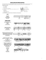
Installation Manual<strong>HKS</strong> <strong>700T</strong>4. EXHAUST SYSTEMBefore tightening each individual part, please fit the entire system first exhaustmanifolds, junctions and muffler.4.1 Preparing the exhaust manifoldsProceed to 4.2 if using an <strong>HKS</strong> supplied exhaust manifold.• To create a custom exhaust manifold, refer to the engine and mufflerlayout in FIG. 3 for a basic reference.• On the engine side, weld the flange to the manifold pipe.4.2 Installing the exhaust manifold• Place the exhaust gasket between the exhaust flange and the exhaustport of the engine (refer to Fig.3).• Tighten the nuts evenly so that the flange will seat flat.4.3 Installing the muffler• Extend the exhaust outlet with additional stainless tubing if needed.• Insert the manifold pipe into the muffler and attach with the springsprovided.• Use rubber isolators in the design of the muffler mount between theexhaust system and the airframe.CAUTION!Rubber isolators must be used to mount the muffler, otherwise damage tothe exhaust system will occur.9
Installation Manual<strong>HKS</strong> <strong>700T</strong>Gasket EXBoss(PT 1/8)M8 Nut (Self lock)Manifold LH 1SpringManifold LH 2Face each other like this.Use Wire Lock for all springs.Fig.3-1 Exhaust System10
Installation Manual<strong>HKS</strong> <strong>700T</strong>FlangeGasket Turbine OutletPipeMake this pipe for your application.SpringM8 Nut (Self lock)Flexible Joint MaleFlexible Joint FemalePipeMake this pipe for your application.Length between flange surface and flex jointmust be within 150mm.Fig.3-2 Exhaust System11
Installation Manual<strong>HKS</strong> <strong>700T</strong>5. LUBRICATION SYSTEM5.1 Installing the dry sump oil tankPlease pay attention to the following for the oil tank installation(Refer to Fig.4).• The oil tank cap must be between 125mm. (5in.) above and 200mm.(7-3/4in.) below from the mounting bosses when the tank is mounted.• To avoid heat, keep the tank away from the exhaust system.• Mount the tank in a position to keep the hose between the oil tank outletand engine inlet ('A' in Fig 4.) as short as possible.5.2 Installing the oil coolerPlease pay attention to the following for the oil cooler installation(Refer to Fig.4).• Mount the cooler in a position lower than the oil tank.• Mount the cooler in a position that receives unrestricted airflow.• Mount the oil cooler so that the cooler core is at a right angle (90 Deg.) tothe local airflow.• The oil inlet and outlet should be upwards.CAUTION!The oil cooler must be mounted below the dry sump oil tank. If the cooleris located higher there is the possibility of oil overflowing from the tankafter shutting down the engine.12
Installation Manual<strong>HKS</strong> <strong>700T</strong>5.3 Installing the oil linesFollow Fig.4 for oil line connections.• Cut the hose to appropriate length so that there are no tight bends (wherethe hose might kink and restrict the flow of oil). Use elbow fittings whenchanging hose direction.• Follow the hose manufacturer's instructions when attaching the fittings tothe hose ends.• Avoid the hose from touching the engine case. Clamp and protect the oillines to avoid chafing and allowing vibration to weaken the hoses andconnections.• Tighten the fittings securely.• Oil tank vent line ('B' in Fig.4): Inner diameter is 8mm (5/16 in) minimum.Should make shorter than 1000mm, to minimize the accretion of ice andmust first go upwards 100mm. (4in.) or more from the oil tank union andthen downward and led out of the plane.Hose length and fittings will vary with engine and auxiliary equipment layout.Please see the Aeroquip Catalogue for fitting types and hose assemblyinstructions.Recommended oil hoseRecommended hose fittings: Aeroquip AQP Racing Hose FBA1000: Aeroquip S.A.E. 37deg. swivelCAUTION!• Please use the specified hose and fittings for oil lines.Inner diameter of oil line is 13mm (1/2in) minimum. The placement andmaterials of the oil lines used must minimize the probability of theoccurrence and spread of fire by using following.• Shielding or locating components to safeguard against the ignition ofleaking oil.• Should be covered by fire-resistant sleeve if necessary.• Oil line damage resulting in oil loss can cause engine damage or failure.13
Installation Manual<strong>HKS</strong> <strong>700T</strong>Oil Tank AssyAB200 125Min.100Oil Cooler(04Y-425)Boss for Oil Temp.SensorNPT1/8 ThreadHose fittings must be attached to both ends of the AQP Racing Hose.Fig.4-1 Lubrication System Diagram14
Installation Manual<strong>HKS</strong> <strong>700T</strong>Hose fittings must be attached to both ends of the AQP Racing Hose.Fig.4-2 Lubrication System Diagram15
Installation Manual<strong>HKS</strong> <strong>700T</strong>Hose fittings must be attached to both ends of the AQP Racing Hose.Fig.4-3 Lubrication System Diagram16
Installation Manual<strong>HKS</strong> <strong>700T</strong>6. FUEL SYSTEMFuel is supplied to the four injectors by the electric fuel pump.6.1 Installing the Fuel PumpPlease pay attention to the following for the fuel pump installation(Refer to Fig.5-1 and Fig.5-2).• The fuel pump must be located below the fuel tank level.• Mount the fuel pressure regulator securely with two 6mm. bolts (SeeFig.5-1).6.2 Installing the Fuel Lines• <strong>HKS</strong> high pressure fuel hoses and clips must be used between the fuelpump, the fuel pressure regulator, the <strong>HKS</strong> high pressure fuel filter andthe engine (See Fig.5-2).• Adjust the fuel lines to appropriate length so that there are no tight bends(where the fuel lines might kink and cut off fuel flow).• Avoid the fuel lines from touching the engine, clamp and protect the fuellines to avoid chafing and allowing vibration to weaken the hoses andconnections.• Fit a <strong>HKS</strong> high pressure fuel filter between the fuel pressure regulator andthe engine (See Fig.5-2).• Fit a general purpose low pressure fuel filter between the fuel tank andthe fuel pump (See Fig.5-2).• All fuel line connections must be secured with hose clamps or otherapproved methods.CAUTION!Please carefully follow the instructions in 6.1 for the fuel pump installation.An improper installation causing improper pump operation will lead toengine stoppage or fuel leak.The placement and materials of the fuel lines used must minimize theprobability of the occurrence and spread of fire by following. Using fire-resistant lines, fittings, and other components that containa fuel. Shielding or locating components to safeguard against the ignitionof leaking fuel. Should be covered by fire-resistant sleeve if necessary.17
Installation Manual<strong>HKS</strong> <strong>700T</strong>Bolt M6-60Fuel Pressure RegulatorCollarAdapter Assy Fuel RegulatorNut M6Tightening torque: 1.2kgf・m (11N・m)Fig.5-118
Installation Manual<strong>HKS</strong> <strong>700T</strong>φ4 Hoseφ8 Hose<strong>HKS</strong>FuelFilterClipFuelPressureRegulatorFuelPumpLowPressureFilterFuel TankFuel TankTo EngineHigh pressure line (<strong>HKS</strong> Fuel hoses & Clips must be used.)Fig.5-219
Installation Manual<strong>HKS</strong> <strong>700T</strong>6.3 Air CleanerFix with a Wire Lock using a hole.Pipe SuctionAir CleanerHose φ45 L55Band Hose #28Fix Air Cleaner and Suction Pipe with a Wire Lock.Fix Suction Pipe and Actuator bracket of turbo with a Wire Lock.All hose bands need to be fixed with Wire Locks.Fig.5-320
Installation Manual<strong>HKS</strong> <strong>700T</strong>6.4 IntercoolerIntercooler pipeRecommended specification: Outer diameter φ45 Thickness 1.5mm Aluminum pipe.Minimum diameter: φ40.Hoses for connection of intercooler pipes:Select hoses that acceptable pressure is more than 1.5kg/cm2, heat level is more than180 degree C (356 degree F) and durable against oil.Fix intercooler pipes to prevent disconnection of pipes.Use wire lock or similar item for all intercooler pipe components to prevent falling of them.PipeMake these pipes using φ45 pipe for your application.Weld bosses for your application.IntercoolerHose φ65 L55Band Hose #40Hose φ45 L55Band Hose #28Pipe SuctionHose φ38 L55Band Hose #28PipeMake this pipe using φ45 pipe for your application.Fig.5-421
Installation Manual<strong>HKS</strong> <strong>700T</strong>7. ELECTRICAL EQUIPMENTPlease refer to the electric equipment diagram in Fig6.7.1 Ignition Coil InstallationPlease pay attention to the following for the ignition coil installation.• Two ignition coils are used. The coils come with factory installedconnectors.• Mount the coils where the ignition cables can reach the spark plugs, but ina position where they will be properly cooled with airflow during engineoperation. The maximum ambient temperature is 140 Deg. F (60 Deg. C).WARNING!Do not mount the ignition coils on the engine itself. The coils must beproperly cooled during engine operation.7.2 Regulator InstallationPlease pay attention to the following for the regulator installation.• Mount the regulator where the maximum ambient temperature is 140 Deg.F (60 Deg. C).WARNING!The maximum ambient temperature of the ignition system is 140 Deg. F(60 Deg. C).7.3 BatteryThe battery is an important component in the <strong>HKS</strong> <strong>700T</strong> ignition system.• The battery must be 12 volt.• Battery must have at least 14Ah capacity.Use a sealed lead acid type battery, and they are commonly used onrecreational motor craft, such as "Quad type" All terrain vehicles (ATVs).22
Installation Manual<strong>HKS</strong> <strong>700T</strong>7.4 Starter RelayA starter relay (04Y-309) must be used to run the starter motor (refer to Fig.6).7.5 FuseFuses must be installed in the following places.• Between the charging circuit (regulator) and main power supply, 20Amp.• Between the electrical accessory terminal (shown as user load terminal inFig.6) and the main power supply.The fuse requirement will vary with the accessories load.7.6 WiringPlease follow the wiring diagram in Fig.6. If an extension lead is required,please order terminal connectors.7.6.1 Ignition CablesIgnition Coil 1 is for center spark plugs of both cylinders. Ignition Coil 2 is for sidespark plugs. Refer to Fig.6 for connections. To avoid shorting the cable orbreakage, keep the cables away from touching cylinders or cylinder heads.Protect with spiral cut polyethylene tubing, a fuel line/tie-wrap standoff or clampif necessary.7.6.2 RegulatorUse the harness regulator (<strong>Inc</strong>luded in package).• Regulator to the AlternatorConnect the 3P connector (three white wires).• Regulator to the Power supplyInsert a 20 amp. fuse to the red wire from the regulator and connect to thepositive side of the power supply. Connect the black wire to ground.7.6.3 Starter MotorInstall a starter relay and connect as in the wiring diagram.WARNING!• Use a minimum of 10mm 2 (6 gauge) or heavier, flexible, multi strandcable for the following:(1) The starter motor to power supply cable(2) The engine ground cable*(3) The battery ground cable23
Installation Manual<strong>HKS</strong> <strong>700T</strong>*Note: Do not forget the engine ground cable (2). This cable must beconnected to the bolt that attaches the starter motor to the engine.WARNING!• Locating components to safeguard against the ignition of leaking fuel.Should be insulated by fire-resistant materials if necessary.24
Installation Manual<strong>HKS</strong> <strong>700T</strong>Connect to IG Coil 1Connect to IG Coil 2Connect to IG Coil 1Connect to IG Coil 2Fig.6-225
Installation Manual<strong>HKS</strong> <strong>700T</strong>8. ENGINE INSTRUMENTSIn order to run the engine properly, the following instruments are required tomonitor the <strong>HKS</strong> <strong>700T</strong> operating conditions.(1) Engine tachometerFollowing two lines are usable for sensing the revolution.* The trigger line for the ignition coil. (1 pulse/rev)Install the genuine tachometer (04Y-352) at this line.* The AC line of the generator. (6 pulses/rev)WARNING!Do not use the signal from the pulser of engine to avoid the miss firing.(2) CHT (Cylinder Head Temperature gauge)Connect wires (Red: Positive / White: Negative) of Type K thermo coupleCHT sensor to the meter.(3) Oil temperature gaugeInstall the oil temperature sender (sensor) in the threaded boss at the bottomof the oil tank the thread 1/8" NPT. See Fig.4.(4) Oil pressure gaugeInstall the oil pressure sensor to the plugged hole near the oil filter mount onthe rear cover, the thread is 1/8" NPT. Remove the tapered plug, which hasbeen inserted before shipping.26
Installation Manual<strong>HKS</strong> <strong>700T</strong>(5) Ammeter or VoltmeterAn ammeter or voltmeter is required to monitor if the battery charging circuitis operating properly and the charge condition of the battery. An additionaluse of this instrument is to detect a possible malfunction of the alternator,regulator or if the current drain of accessories are more than the chargingcircuit can supply.WARNING!Minimum voltage for the ignition systems operating is 9 volts.If the battery charging circuit is not operating properly (such as regulatorfailure, etc.), the engine will be running with electricity from the batteryonly. If the engine continues to run in this condition, the engine willeventually stop from the ignition completely discharging the battery.Land as soon as is safely possible!(6) EGT (Exhaust Gas Temperature gauge)Install the exhaust gas temperature sending units (sensors) at 20mm apartfrom the exhaust port flange. In order to get accurate EGT, install this sensorat the rear side of the exhaust pipe to avoid the direct airflow.27
Installation Manual<strong>HKS</strong> <strong>700T</strong>9. PROPELLER9.1 RotationThe propeller shaft rotates clockwise looking at the propeller-mounting flangefrom the front (see Fig.8).Please take this into account when choosing a propeller for the specific engineinstallation configuration (tractor, pusher).9.2 Prop flange dimensionsThere are three ways to install the propeller to this engine.(1) Use 8mm.x1.25 bolts to mount using the threaded bores on the flange.(P.C.D 80mm)(2) Mount with AN4 bolts and nuts. (P.C.D. 75mm)(3) Mount with AN5 bolts or 8mm bolts with nuts. (P.C.D. 101.6mm)Dimensions for the propeller-mounting flange are shown in Fig.8.Fig.8 Propeller Mounting Flange Dimensions28
Installation Manual<strong>HKS</strong> <strong>700T</strong>10. CONTROL CABLESUse wire cables for throttle operation. A throttle wire cables are available as anoption parts. Please see the parts list.29
Installation Manual<strong>HKS</strong> <strong>700T</strong>11. STARTING ENGINE THE FIRST TIME• Recheck the wiring according the electrical schematic in Fig.6.• Fill the oil tank with the recommended oil (See the operators manual fortype), The minimum amount is 3 liters of oil. This will vary with the specificinstallation.• Check the range and free movement of the throttle lever. (NOTE 19)When starting the engine the first time, with the ignition OFF, crank theengine with the starter for supplying oil into the engine. If using theminimum size battery connecting a bigger capacity battery may berequired.Engine instruments must be installed to monitor the engine operatingconditions. (Refer to Sec.9.)• Ignition and Main switch OFF.• Remove all four spark plug caps and remove the upper plugs on the leftand right cylinders.• Main switch ON.• Engage the starter and confirm if oil pressure registers on the oil pressuregauge. If not, check the oil lines and the oil pressure sensing system.• Main switch OFF.• Reinstall the spark plugs and attach the plug caps.• Make certain that there is adequate fuel in the fuel tank and that the fuelpump is operating properly. (Refer to Chapter 6.1)• Please refer to the more specific operating instructions found in Chapter5.1 in operations manual.30
Installation Manual<strong>HKS</strong> <strong>700T</strong>Log of revisions.Revision Date Pages affected Description SignatureNo.3a