
You also want an ePaper? Increase the reach of your titles
YUMPU automatically turns print PDFs into web optimized ePapers that Google loves.
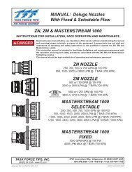
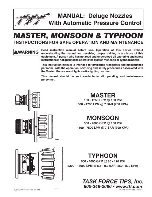
MANUAL: Deluge NozzlesWith Automatic Pressure ControlMASTER, MONSOON & TYPHOONINSTRUCTIONS FOR SAFE OPERATION AND MAINTENANCEWARNINGRead instruction manual before use. Operation of this device withoutunderstanding the manual and receiving proper training is a misuse of thisequipment. A person who has not read and understood all operating and safetyinstructions is not qualified to operate the Master, Monsoon or Typhoon nozzle.This instruction manual is intended to familiarize firefighters and maintenancepersonnel with the operation, servicing and safety procedures associated withthe Master, Monsoon and Typhoon firefighting nozzles.This manual should be kept available to all operating and maintenancepersonnel.TASK FORCE TIPSMASTER150 - 1250 GPM @ 100 PSI600 - 4700 LPM @ 7 BAR (700 KPA)MONSOON300 - 2000 GPM @ 100 PSI1100 - 7500 LPM @ 7 BAR (700 KPA)TYPHOON600 - 4000 GPM @ 80 - 120 PSI2300 - 15000 LPM @ 5.5 - 8.3 BAR (550 - 830 KPA)©Copyright <strong>Task</strong> <strong>Force</strong> <strong>Tips</strong>, Inc. 1999TASK FORCE TIPS, Inc.800-348-2686 • www.tft.com<strong>LIM</strong>-<strong>030</strong> November 22, 1999 Rev 1
TABLE OF CONTENTS1.02.02.12.22.32.42.52.63.03.13.23.33.44.05.06.0MEANING OF SIGNAL WORDSGENERAL INFORMATIONUSE WITH SALT WATERVARIOUS MODELS AND TERMSHYDRAULIC INSTALLATIONELECTRIC INSTALLATIONPATTERN CONTROLUSE WITH FOAM2.6.1 FOAMJET LX WITH MASTER NOZZLEAUTOMATIC NOZZLE OPERATIONFLOW CHARACTERISTICS OF MASTER AND MONSOONFLOW CHARACTERISTICS OF TYPHOONDETERMINING FLOW WITH PRE-PIPED MONITORSSTREAM TRAJECTORY DATAFLUSHING DEBRISMAINTENANCEWARRANTY1.0 MEANING OF SIGNAL WORDSA safety related message is identified by a safety alert symbol and a signal word to indicate the level of risk involvedwith a particular hazard. Per ANSI standard Z535.4-1998 the definitions of the three signal words are as follows:DANGERWARNINGDANGER indicates an imminently hazardous situation which, if not avoided,will result in death or serious injury.WARNING indicates a potentially hazardous situation which, if not avoided,could result in death or serious injury.CAUTIONCAUTION indicates a potentially hazardous situation which, if not avoided,may result in minor or moderate injury.2©Copyright <strong>Task</strong> <strong>Force</strong> <strong>Tips</strong>, Inc. 1999<strong>LIM</strong>-<strong>030</strong> November 22, 1999 Rev 1
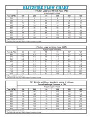
2.0 GENERAL INFORMATIONThe <strong>Task</strong> <strong>Force</strong> <strong>Tips</strong> Master, Monsoon and Typhoon nozzles are automatic pressure control deluge nozzles. Theseautomatic nozzles operate by sensing the pressure at the nozzle's inlet and adjusting the discharge opening to maintain aconstant pressure throughout the flow range of the nozzle. While flowing, the stream pattern can be varied from wide fogto straight stream. Trapped debris can be removed without the use of tools.These nozzles are constructed of hardcoat anodized aluminum and UV resistant rubber. Their rugged construction iscompatible with the use of fresh water as well as firefighting foam solutions. A summary of each nozzle's characteristics isshown in the table below.FLOW FLOW PRESSURE PRESSURE STANDARDSERIES (GPM) (LPM) (PSI) (BAR, KPA/100) COUPLINGMASTER 150-1250 600-4700 100 7 2.5" NH FEMALEMONSOON 300-2000 1100-7500 100 7 3.5" NH FEMALETYPHOON 600-4000 2300-15000 80-120 5.5-8.3 6" ANSI 150 FLANGENOTES ON ABOVE TABLE: Other threads, coupling sizes or connector styles can be specified at time of order. Master nozzle is also available in selectable gallonage or fixed orifice models. See catalog for details. Typhoon nozzle is field adjustable within the range of pressures shown. For long term installations, it is recommended that the threads be greased before installing the nozzle.OPERATING NOTE ABOUT AUTOMATIC NOZZLES: The automatic nozzle is considerably different than"conventional" nozzles because of basic changes in the operating principle. These differences not only assure the mosteffective operation under a variety of conditions, but will also utilize the available water supply most efficiently. It isimportant that nozzle operators, pump operators, and officers be fully aware of these differences. Therefore, properinstruction is required for safe and effective operations.WARNINGCAUTIONCAUTIONWARNINGWARNINGThis equipment is intended for use by trained personnel for firefighting. Their use forother purposes may involve hazards not addressed by this manual. Seek appropriateguidance and training to reduce risk of injury.Nozzle must be properly connected. Mismatched or damaged threads may cause nozzleto leak or uncouple under pressure and could cause injury.Do not couple aluminum to brass. Dissimilar metals coupled together can cause galvaniccorrosion that can result in inability to unscrew threads or complete loss of threadengagement.Injury can occur from an inadequately supported nozzle. The mounting must be capableof supporting the nozzle reaction force which can be in excess of 2300 lbs (4000 GPM at120 PSI).Some volatile liquids can be ignited by static discharge.Static build-up can occur from: Electrochemical separation of charge as water drains through low conductivity,refined products. Applying foam over a low conductivity liquid of sufficient depth to retain thecharge created as the foam blanket drains.1 Streaming currents as water or foam is introduced into the storage tank.WARNINGWater is a conductor of electricity. Application of water solutions on high voltageequipment can cause injury or death by electrocution. The amount of current that may becarried back to the nozzle will depend on the following factors:Voltage of the line or equipmentDistance from the nozzle to the line or equipmentSize of the streamWhether the stream is solid or broken2Purity of the water1 Electrostatic Hazards of Foam Blanketing Operations by Peter Howels. Industrial Fire Safety July/August 19932 The Fire Fighter and Electrical Equipment, The University of Michigan Extension Service, Fourth Printing 1983. Page 47.3©Copyright <strong>Task</strong> <strong>Force</strong> <strong>Tips</strong>, Inc. 1999<strong>LIM</strong>-<strong>030</strong> November 22, 1999 Rev 1
2.1 USE WITH SALT WATERUse with salt water is permissible provided nozzle is thoroughly cleaned with fresh water after each use. The servicelife of the nozzle may be shortened due to the effects of corrosion and is not covered under warranty.2.2 VARIOUS MODELS AND TERMSThe spray pattern is changed from wide fog to straight stream by means of the "stream shaper". Models are availablewith five different methods to move the stream shaper as shown in figures 1A - 1E. See catalog for model numbersand details.Halo RingCouplingStream Shaper Serial Number BumperHydraulic PortsTASK FORCE TIPSTASK FORCE TIPS TASK FORCE TIPSFig 1A Stream Shaper movedmanually by rotating "halo ring"Fig 1C Stream Shaper movedremotely by hydraulicsManual Override Knob(Master & Monsoon Only)TASK FORCE TIPSFig 1B Stream Shaper movedmanually by rotating "bumper"LeverHold lever down and turn knobfor manual override.Fig 1D Stream Shaper movedremotely by electricity (12-24 volts)4©Copyright <strong>Task</strong> <strong>Force</strong> <strong>Tips</strong>, Inc. 1999Fig 1E Stream Shaper movedby linear (push/pull) motionfrom user's mechanismFIG 1 - Methods for Moving Stream Shaper<strong>LIM</strong>-<strong>030</strong> November 22, 1999 Rev 1
2.3 HYDRAULIC INSTALLATIONOn nozzles with hydraulic stream shaper actuation, the hydraulic system is connected to the nozzle with two 1/8"-27 NPTfemale ports on the filter block located on the nozzle's stream shaper. When the port on the left of the filter block (as seenfrom behind the nozzle) is pressurized, the shaper moves back into the wide fog position. Pressurizing the right portmoves the shaper forward into straight stream. Hydraulic lines must be flexible to allow for movement of the streamshaper.Use only clean fluid compatible with DuPont Viton Fluoroelastomer. System must be free from all dirt, chips, andcontaminants. Replacement filter elements are available from <strong>Task</strong> <strong>Force</strong> <strong>Tips</strong> (item #M160). Maximum hydraulicpressure is 1000 PSI (70 BAR, 7000 KPA).2.4 ELECTRIC INSTALLATIONNozzles with electric stream shaper actuation are shipped with a wiring diagram (TFT item #<strong>LIM</strong>-040). Otherdocumentation is available on request. The actuator is not rated as ignition proof, explosion proof, or intrinsically safe.NOTE: Master and Monsoon nozzles are equipped with manual override in case of electrical power failure. Refer to figure1D for manual override instructions.WARNING2.5 PATTERN CONTROLTFT's Master, Monsoon and Typhoon have full pattern control from straight stream to wide fog. On models with manualshapers, turning the stream shaper clockwise (as seen from the operating position behind the nozzle) moves the shaperto the straight stream position. Turning the stream shaper counterclockwise will result in an increasingly wider pattern.Since the stream trim point varies with flow, the nozzle should be "trimmed" after changing the flow to obtain thestraightest and farthest reaching stream. To properly trim a stream, first open the pattern to narrow fog. Then close thestream to parallel to give maximum reach. Note: Turning the shaper further forward will cause stream crossover andreduce the effective reach of the nozzle.2.6 USE WITH FOAMThe electric motor and other components are ignition sources. The electric streamshaper should be operated only in areas where there is adequate ventilation and nohazard of flammable vapor buildup.The Master, Monsoon and Typhoon nozzles may be used with foam solutions. Refer to fire service training for the properuse of foam.WARNINGWARNINGFor Class B fires, lack of foam or interruption in the foam stream can cause a break in thefoam blanket and greatly increase the risk of injury or death. Assure that: Application rate is sufficient (see NFPA 11 or foam manufacturer'srecommendations). Enough concentrate is on hand to complete task (see NFPA for minimum durationtime requirements). Foam logistics have been carefully planned. Allow for such things as:Storage of foam in a location not exposed to the hazard it protects.Personnel, equipment and technique to deliver foam at a rapid enough rate.Removal of empty foam containers.Clear path to deliver foam, as hoses and other equipment and vehicles aredeployed.Improper use of foam can result in injury or damage to the environment. Follow foammanufacturer's instructions and fire service training to avoid: Using wrong type of foam on a fire, i.e. Class A foam on a Class B fire. Plunging foam into pools of burning liquid fuels. Causing environmental damage. Directing stream at personnel.WARNING©Copyright <strong>Task</strong> <strong>Force</strong> <strong>Tips</strong>, Inc. 1999There is a wide variety of foam concentrates. Each user is responsible for verifying thatany foam concentrate chosen to be used with this unit has been tested to assure that thefoam obtained is suitable for the purpose intended.5<strong>LIM</strong>-<strong>030</strong> November 22, 1999 Rev 1
2.6.1 FOAMJET LX WITH MASTER NOZZLETo increase the expansion ratio, <strong>Task</strong> <strong>Force</strong> <strong>Tips</strong> "Foamjet LX" (model FJ-LX-M) may be used with the Master nozzle. Thislow expansion foam tube attaches and detaches quickly from the nozzle. Adjust nozzle spray pattern to give best foamquality. Note: As expansion ratio is increased, the reach of the nozzle will be decreased due to the greater amount ofbubbles in the stream and their inability to penetrate the air. Generally the reach with foam is approximately 10% less thanwith water only. Actual results will vary based on brand of foam, hardness of water, temperature, etc.3.0 AUTOMATIC NOZZLE OPERATIONAutomatic nozzles operate by sensing the pressure at the nozzle's inlet and adjusting the discharge opening to maintaina constant pressure throughout the flow range of the nozzle. For example, when the pressure at the inlet increases, theexit area is automatically increased until the inlet pressure returns to the nominal pressure of the nozzle.Note: Inlet pressure of the Master, Monsoon and Typhoon nozzle will stabilize at the nominal pressure (within 5%). Thisstabilization may take as long as half a minute after a change in inlet pressure.3.1 FLOW CHARACTERISTICS OF MASTER AND MONSOONWithin its flow range, the Master and Monsoon automatic nozzles operate at the nominal pressure of 100 PSI (7 BAR,700 KPA). Figures 2A and 2B show typical performance of these nozzles.WARNINGAn inadequate supply of nozzle pressure and/or flow will cause an ineffective stream andcan result in injury, death or loss of property.FLOW (LPM)0200040006000PRESSURE (PSI)16014012010080604020OPERATING ENVELOPEPER NFPA 1964108642PRESSURE (BAR, KPA/100)0 00 200 400 600 800 1000 1200 1400 1600 1800 2000FLOW (GPM)FIG 2A - Master Pressure PerformanceEXCEL\TFT\MISC\DELUGE_FLOW6PRESSURE (PSI)016014012010080604020©Copyright <strong>Task</strong> <strong>Force</strong> <strong>Tips</strong>, Inc. 19992000FLOW (LITERS/MIN)4000 6000 80000 00 400 800 1200 1600 2000 2400 2800FLOW (GPM)FIG 2B - Monsoon Pressure Performance10000OPERATING ENVELOPEPER NFPA 1964108642PRESSURE (BAR, KPA/100)EXCEL\TFT\MISC\DELUGE_FLOW<strong>LIM</strong>-<strong>030</strong> November 22, 1999 Rev 1
3.2 FLOW CHARACTERISTICS OF TYPHOONThe Typhoon's nozzle pressure is user adjustable from 80 to 120 PSI (5.5-8.3 BAR, 550-830 KPA). Pressure adjustment ismade by turning a knob, on the front of the nozzle, to the desired pressure setting. The Typhoon will operate at the setpressure anywhere within its flow range of 600 to 4000 GPM (2300-15000 LPM). Figure 3 shows typical performance ofthe Typhoon nozzle.PRESSURE (PSI)16014012010080604020FLOW (LITERS/MIN)0 5000 10000 15000 20000FLOW RANGE120 PSI SETTING110 PSI SETTINGFLOW (GPM)FIG3-Typhoon Pressure Performance3.3 DETERMINING FLOW WITH PRE-PIPED MONITORS100 PSI SETTING90 PSI SETTING80 PSI SETTING000 1000 2000 3000 4000 5000 6000The simplest procedure to determine flow with automatic nozzles is with a flow meter. If a flow meter is unavailable, thenthe flow may be estimated using pressure loss data between the nozzle and an in-line pressure gauge at the pump orconsiderably upstream from the nozzle. Data is taken with a smooth bore nozzle and handheld pitot gauge. Note:Equations assume no substantial change in elevation between in-line pressure gauge and nozzle.108642PRESSURE (BAR, KPA/100)EXCEL\TFT\MISC\DELUGE_FLOWStep1: Determine flow of smooth bore nozzle.Flow water with a smooth bore nozzle and record the nozzle's size, pitot pressure and in-line pressure gaugereading. The smooth bore nozzle's flow is calculated from the Freeman formula:2Q =FxD PsmoothpitotWhere: F = 29.71 for English units (GPM, INCHES, PSI)F = .667 for metric units (LPM, MM, BAR) Note: 1 BAR=100 KPAQsmoothflow in GPM (or LPM)D exit diameter in INCHES (or MM)P pitot pressure in PSI (or BAR)pitotStep 2: Find pressure loss constant.Using the results from step 1, use the following equation to calculate the pressure loss constant between the in-linepressure gauge and the nozzle:C=PQ 2 smoothin-line- PpitotWhere: CPinline©Copyright <strong>Task</strong> <strong>Force</strong> <strong>Tips</strong>, Inc. 19992 2piping pressure loss constant in GPM /PSI (or LPM /BAR)in-line pressure gauge reading in PSI (or BAR)7<strong>LIM</strong>-<strong>030</strong> November 22, 1999 Rev 1
Step 3: Calculate flow with automatic nozzle.Using the pressure loss constant from step 2 and the following equation, the flow with an automatic nozzle can becalculated for your particular installation.Where:QPautoautoQ = (P - P )Cauto in-line autoautomatic nozzle flow in GPM (or LPM)nominal nozzle operating pressure in PSI (or BAR)Mount a graph or table of the results adjacent to the in-line pressure gauge. Deliver any desired flow by adjustment ofpump pressure.3.4 STREAM TRAJECTORY DATAFigures 4A and 4B give the stream trajectory for the Master, Monsoon and Typhoon nozzles at various flows.Notes on trajectory graphs:• Graphs show approximate effective stream trajectory at 30 degrees elevation in no windconditions. Distance to last water drops approximately 10% farther.• Trajectories shown are for water. The addition of foam is expected to decrease the reach by 10%.• Tail or head winds of 20 MPH (30 KPH) may increase or decrease the range approximately 30%.• Stream trajectory of Typhoon based on "The Trajectories of Large Fire Fighting Jets" by A.P. Hattonand M.J. Osborne, Reference: "The International Journal of Heat and Fluid Flow", Vol 1 No 1.VERTICAL DISTANCE (FEET)0102<strong>030</strong>METERS40 5080702060 MASTER, 100 PSI (7 BAR, 700 KPA )50D401<strong>030</strong>20AEB10C0 00 20 40 60 80 100 120 140 160 180 200 220 240 260 280 300HORIZONTAL DISTANCE (FEET)607080 90METERSCURVEABCDECURVEABCDEGPMFLOW3004005008001000LPMFLOW11001500190<strong>030</strong>003800LBSREACTION150200260400510KGFREACTION7090120180230EXCEL\MISC\RANMASTVERTICAL DISTANCE (FEET)807060504<strong>030</strong>2010METERS0 10 20 30 40 50 60 70 80 90MONSOON, 100 PSI (7 BAR, 700 KPA)A000 20 40 60 80 100 120 140 160 180 200 220 240 260 280 300HORIZONTAL DISTANCE (FEET)EXCEL\MISC\RAN_MONBCDE2010METERSCURVEABCDECURVEABCDEGPMFLOW300600100015002000LPMFLOW11002300380057007500LBSREACTION16<strong>030</strong>05107601000KGFREACTION701402303404508©Copyright <strong>Task</strong> <strong>Force</strong> <strong>Tips</strong>, Inc. 1999FIG 4A - Master and Monsoon Stream Trajectory<strong>LIM</strong>-<strong>030</strong> November 22, 1999 Rev 1
VERTICAL DISTANCE (FEET)METERS0 204060 80 100 12010<strong>030</strong>80 TYPHOON, 80 PSI (5.5 BAR, 550 KPA)60D2040AE1020B0C00 40 80 120 160 200 240 280 320 360 400HORIZONTAL DISTANCE (FEET)EXCEL\TFT\TYPHOON80METERSCURVEABCDECURVEABCDEGPMFLOW6001000200<strong>030</strong>004000LPMFLOW2300380076001100015000LBSREACTION28047095014001900KGFREACTION130210430640860VERTICAL DISTANCE (FEET)100806040200METERS0 20 40 60 80100 120TYPHOON 100 PSI (7 BAR, 700 KPA)AB0 40 80 120 160 200 240 280 320 360 400HORIZONTAL DISTANCE (FEET)CDE3020100METERSCURVEABCDECURVEABCDEGPMFLOW6001000200<strong>030</strong>004000LPMFLOW2300380076001100015000LBSREACTION320530110016002100KGFREACTION150240500730950EXCEL\TFT\TYPHOON102VERTICAL DISTANCE (FEET)METERS0 20 40 60 80100 1201009080 TYPHOON, 120 PSI (8.3 BAR, 830 KPA)7060C5040D30AE20B1000 40 80 120 160 200 240 280 320 360 400HORIZONTAL DISTANCE (FEET)3020100METERSCURVEABCDECURVEABCDEGPMFLOW6001000200<strong>030</strong>004000LPMFLOW2300380076001100015000LBSREACTION350580120017002300KGFREACTION1602605507701000EXCEL\TFT\TYPHOON116©Copyright <strong>Task</strong> <strong>Force</strong> <strong>Tips</strong>, Inc. 1999FIG 4B - Typhoon Stream Trajectory9<strong>LIM</strong>-<strong>030</strong> November 22, 1999 Rev 1
4.0 FLUSHING DEBRISDebris in the water may get caught inside the nozzle. This trapped material will cause poor stream quality, shortenedreach and reduced flow. To remove debris trapped in the nozzle:1. Shut off flow to the nozzle.2. Move the stream shaper to the wide fog position.3. Carefully unscrew and remove the nozzle's piston/cylinder.Notes on Master Nozzle:• The cylinder is under about 25 lbs (11Kgf) of spring force. The spring must becompressed to reinstall.• A long white push rod is part of the cylinder assembly. Pull cylinder straight out until pushrod clears shaft.Notes for Monsoon and Typhoon:• The cylinder and piston will come out as a unit.• Remove the small spring and stainless steel poppet from the center of the shaft.4. Remove debris.5. Reassemble the nozzle.Figures 5A, 5B & 5C show the pieces that are removed during the flush procedure.WARNINGLarge amounts of debris may be unflushable and can reduce the flow of the nozzleresulting in an ineffective flow. In the event of a blockage, it may be necessary to retreat toa safe area.PISTONRETURN SPRINGPUSH RODCYLINDERSPRAY LUBESHAFTLUBELUBELUBETFT\MASTER\MTFT_ISOFIG 5A - Master Nozzle Front End Parts10©Copyright <strong>Task</strong> <strong>Force</strong> <strong>Tips</strong>, Inc. 1999<strong>LIM</strong>-<strong>030</strong> November 22, 1999 Rev 1
LUBE LUBE LUBECONTROLSHAFTLUBEPOPPETSPRINGCYLINDERRETURNSPRINGPISTONtft\monsoon\ms_frontFIG 5B - Monsoon Nozzle Front End PartsLUBELUBELUBECONTROLSHAFTLUBEPOPPETSPRINGRETURNSPRINGCYLINDERPISTONtft\typhoon\mt850FIG 5C - Typhoon Nozzle Front End Parts©Copyright <strong>Task</strong> <strong>Force</strong> <strong>Tips</strong>, Inc. 199911<strong>LIM</strong>-<strong>030</strong> November 22, 1999 Rev 1
5.0 MAINTENANCEWhen reassembling the nozzle after repairs or for preventive maintenance, coat the seal on the piston, the inner bore ofthe cylinder and the shaft slide surface with a waterproof lubricant such as Dow Corning #44 Silicone Grease. Lubricationis required to assure continued smooth operation. The frequency of lubrication will depend on frequency of usage andstorage conditions. Nozzles must be checked regularly to assure proper operation. See figures 5A, 5B and 5C for thenozzle lubrication points.Contact factory for parts lists and exploded views for particular models. Each nozzle is identified by a serial numberlocated on the nozzle's stream shaper (see figure 1).6.0 WARRANTY<strong>Task</strong> <strong>Force</strong> <strong>Tips</strong>, Inc., 2800 East Evans Avenue, Valparaiso, Indiana 46383 ("TFT") warrants to the original purchaser of itsMaster, Monsoon and Typhoon series nozzles ("equipment"), and to anyone to whom it is transferred, that the equipmentshall be free from defects in material and workmanship during the five (5) year period from the date of purchase.TFT's obligation under this warranty is specifically limited to replacing or repairing the equipment (or its parts) which areshown by TFT's examination to be in a defective condition attributable to TFT. To qualify for this limited warranty, theclaimant must return the equipment to TFT, at 2800 East Evans Avenue, Valparaiso, Indiana 46383, within a reasonabletime after discovery of the defect. TFT will examine the equipment. If TFT determines that there is a defect attributable toit, TFT will correct the problem within a reasonable time. If the equipment is covered by this limited warranty, TFT willassume the expenses of repair.If any defect attributable to TFT under this limited warranty cannot be reasonably cured by repair or replacement, TFTmay elect to refund the purchase price of the equipment, less reasonable depreciation, in complete discharge of itsobligations under this limited warranty. If TFT makes this election, claimant shall return the equipment to TFT free andclear of any liens and encumbrances.This is a limited warranty. The original purchaser of the equipment, any person to whom it is transferred, and any personwho is an intended or unintended beneficiary of the equipment, shall not be entitled to recover from TFT anyconsequential or incidental damages for injury to person and/or property resulting from any defective equipmentmanufactured or assembled by TFT. It is agreed and understood that the price stated for the equipment is in partconsideration for limiting TFT's liability. Some states do not allow the exclusion or limitation of incidental or consequentialdamages, so the above may not apply to you.TFT shall have no obligation under this limited warranty if the equipment is, or has been, misused or neglected (includingfailure to provide reasonable maintenance) or if there have been accidents to the equipment or if it has been repaired oraltered by someone else.THIS IS A <strong>LIM</strong>ITED EXPRESS WARRANTY ONLY. TFT EXPRESSLY DISCLAIMS WITH RESPECT TO THEEQUIPMENT ALL IMPLIED WARRANTIES OF MERCHANTABILITY AND ALL IMPLIED WARRANTIES OF FITNESSFOR A PARTICULAR PURPOSE. THERE IS NO WARRANTY OF ANY NATURE MADE BY TFT BEYOND THATSTATED IN THIS DOCUMENT.This limited warranty gives you specific legal rights, and you may also have other rights which vary from state to state.TASK FORCE TIPS, Inc.www.tft.com©Copyright <strong>Task</strong> <strong>Force</strong> <strong>Tips</strong>, Inc. 19992800 East Evans Avenue • Valparaiso , IN 46383-6940800-348-2686 • 219-462-6161 • Fax 219-464-7155<strong>LIM</strong>-<strong>030</strong> November 22, 1999 Rev 1