Angular Modulation and Demodulation
Angular Modulation and Demodulation
Angular Modulation and Demodulation

You also want an ePaper? Increase the reach of your titles
YUMPU automatically turns print PDFs into web optimized ePapers that Google loves.
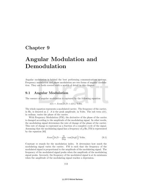
Chapter 9<strong>Angular</strong> <strong>Modulation</strong> <strong>and</strong><strong>Demodulation</strong>Draft<strong>Angular</strong> modulation is behind the best performing communications systems.Frequency modulation <strong>and</strong> phase modulation are two forms of angular modulation.They are both covered with a wealth of detail in this chapter.9.1 <strong>Angular</strong> <strong>Modulation</strong>The essence of angular modulation is captured by the following equations(t) = A cos(2πft + φ(t)) Volts.The whole equation represents a modulated carrier. The frequency of the carrier,in Hz, is denoted as f. A is the peak amplitude, in Volts. The sub term φ(t),in radians, varies the phase of the carrier.With Frequency <strong>Modulation</strong> (FM), the derivative of the phase of the carrieris changed according to the amplitude of the modulating signal. In other words,the modulating signal determines the rate of change of the phase of the carrier.This rate of change is expressed as a fraction of a complete cycle of the signal.Assuming that the modulating signal has a frequency of g Hz, FM is representedby the equation [63](A cos 2πft − m)2πg · cos(2πgt) Volts. (9.1)Constant m st<strong>and</strong>s for the modulation index. It determines how much themodulating signal varies the carrier. FM is such that the frequency of themodulated signal is proportional to the amplitude of the modulating signal. Thefrequency of the modulated signal peaks when the amplitude of the modulatingsignal peaks. Inversely, the frequency of the modulated signal is at its minimumwhen the amplitude of the modulating signal reaches a depression.113(c) 2013 Michel Barbeau
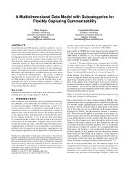
114 CHAPTER 9. ANGULAR MODULATION AND DEMODULATIONExercise 9.1Show that the derivative of the phase of the carrier φ ′ (t) is equal to m·sin(2πgt).Amp. (V)10Carrier−10 0.1 0.2 0.3 0.4 0.5 0.6 0.7 0.8 0.9 1Modulating Signal1Draft0−10 0.1 0.2 0.3 0.4 0.5 0.6 0.7 0.8 0.9 1Phase φ(t)100−100 0.1 0.2 0.3 0.4 0.5 0.6 0.7 0.8 0.9 1Modulated Signal10Amp. (V)Amp. (V)Amp. (V)−10 0.1 0.2 0.3 0.4 0.5 0.6 0.7 0.8 0.9 1Time (s)Figure 9.1: A modulating signal at one Hz varying the frequency of a carrier at20 Hz.Figure 9.1 demonstrates FM on a carrier at frequency 20 Hz. The modulatingsignal is at one Hz. The modulation index is 16π. The phase <strong>and</strong> modulatedsignals are shown in the lower part. Figure 9.1 is produced by the followingOctave script:1 % Create an array of 1000 time instants, in steps of 0.001 s.2 time=[0:999]*0.001;3 % Create a carrier signal at frequency f4 f=20; % Hz(c) 2013 Michel Barbeau
9.1. ANGULAR MODULATION 1155 % Create a carrier6 carrier = cos(2*pi*f*time);7 % <strong>Modulation</strong> index8 m=16*pi;9 % Create a modulating signal at frequency g10 g=1; % Hz11 % Create the modulating signal12 modulatingsignal=sin(2*pi*g*time);13 phase=−m/(2*pi*g)*cos(2*pi*g*time);14 % Create the modulated signal15 modulatedsignal=cos(2*pi*f.*time + phase);16 % Plot the carrier, modulating signal, phase <strong>and</strong> modulated signal17 subplot(4,1,1);18 plot(time,carrier);19 grid on;20 title('Carrier');21 ylabel('Amp. (V)');22 subplot(4,1,2);23 plot(time,modulatingsignal);24 grid on;25 title('Modulating Signal');26 ylabel('Amp.Draft(V)');27 subplot(4,1,3);28 plot(time,phase);29 grid on;30 title('Phase \phi(t)');31 ylabel('Amp. (V)');32 subplot(4,1,4);33 plot(time,modulatedsignal);34 grid on;35 title('Modulated Signal');36 xlabel('Time (s)');37 ylabel('Amp. (V)');The modulating signal at frequency g is generated at line 12. The phase φ(t)is calculated at line 13. Is is used to vary the frequency f of the carrier <strong>and</strong>produce the modulated signal at line 14. The later is the implementation ofEquation 9.1.Exercise 9.2The equation representing phase modulation isA cos(2πf 1 t + m · sin(2πf 2 t)).Modify the example such that Phase <strong>Modulation</strong> (PM) is used instead of FM.Explain the effect of phase modulation on the carrier.(c) 2013 Michel Barbeau
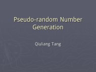
116 CHAPTER 9. ANGULAR MODULATION AND DEMODULATIONExercise 9.3Modify the previous script such that an in-phase FM signal Isignal <strong>and</strong> aquadrature FM signal Qsignal are generated.It is well established that angular modulation, FM <strong>and</strong> PM, is less susceptibleto noise than AM. Under equivalent conditions, angular modulation yields alower bit error rate than AM.9.2 FM <strong>Demodulation</strong>Using the in-phase <strong>and</strong> quadrature of a signal, FM demodulation is accomplishedusing the following equationDraftQ t · I t−1 − I t · Q t−1Volts. (9.2)I t · I t−1 + Q t · Q t−1The following Octave script implements FM demodulation:1 % Get the number of time instants2 S=size(time); L=S(2);3 % Compute the numerator4 numerator = Qsignal(2:L).*Isignal(1:L−1) − ...Isignal(2:L).*Qsignal(1:L−1);5 % Compute the denominator6 denominator = Isignal(2:L).*Isignal(1:L−1) + ...Qsignal(2:L).*Qsignal(1:L−1);7 % Take the ratio of the numerator <strong>and</strong> denominator8 demodulation = numerator ./ denominator;9 % Plot the signal10 plot(time(2:L),8*demodulation);11 % Annotations12 title('Frequency <strong>Demodulation</strong>');13 xlabel('Time (s)');14 ylabel('Amplitude (V)');The variables Isignal <strong>and</strong> Qsignal from the Octave script of Exercise 9.3 areused. Lines 5, 7 <strong>and</strong> 8 implement Equation 9.2. Figure 9.2 shows the plot ofthe demodulated signal.9.3 Phase Shift KeyingPhase Shift Keying (PSK) is a type of PM used for data communications. Bitsare encoded by discrete phase changes in the signal. A possible PSK scheme ispictured in Figure 9.3. The figure represents a constellation of PSK symbols.The points, i.e., the symbols, are distributed evenly around a circle. The circle(c) 2013 Michel Barbeau
9.3. PHASE SHIFT KEYING 1171.5Frequency <strong>Demodulation</strong>1.41.31.2Amplitude (V)1.110.90.8Draft0.70 0.1 0.2 0.3 0.4 0.5 0.6 0.7 0.8 0.9 1Time (s)Figure 9.2: FM demodulation.diameter is not important. What is important is the angle determined by eachpoint. A bit assignment is indicated inside each symbol of the constellation.For instance, the symbol 000 has an angular offset of π/4 radians. In otherwords, when the symbol 000 is sent, the phase of the signal is π/4 radians.This example is an eight-symbol constellation. Three bits are encoded by eachsymbol.The particular scheme illustrated in Figure 9.3 is termed eight-ary PSK. Ingeneral, we may have m-ary PSK, where m is a power of two. If m is equal totwo, then it is called Binary PSK (BPSK) because only one bit can be coded persymbol. If m is equal to four, then it is called Quadrature PSK (QPSK) becausethe angular separation between any two adjacent symbols is π/4 radians. A m-symbol constellation can encode log 2 m bits per symbol.Let i denote the index of a symbol, with i = 1, 2, 3, . . . , m. When symbolwith index i is sent, the value of the signal as a function of time is determinedby the following equation(s(t) = A cos2πft + 2πim). (9.3)(c) 2013 Michel Barbeau
118 CHAPTER 9. ANGULAR MODULATION AND DEMODULATION001010000011π/4111Draft100110101Figure 9.3: An eight-ary PSK constallation. Each point represents a symbol.The angle determined by each point represents the phase of the signal whenthe corresponding symbol is sent. For instance, when symbol 1 is sent, thephase of the signal is π/4 radians. Each symbol can encode three bits. The bitassignment is posted next to the symbol.Exercise 9.4Figure 9.4 shows a QPSK constellation. The Q refers the fact that the adjacentsymbols are in quadrature, i.e., the angular separation between two consecutivesymbols is π/2 radians. The four different points of the constellation allows therepresentation of two bits per symbol. A drawback of this constellation is theabsence of phase shift when symbol with index four is sent, assigned to bits 00.The phase shift is zero radians. This makes determination of symbol start <strong>and</strong>clock recovery harder to make by the receiver when long sequences of zeroes aresent. Design an alternative QPSK constellation that doesn’t have this problem.That is, there is a phase shift marking the start of every symbol.(c) 2013 Michel Barbeau
9.3. PHASE SHIFT KEYING 119010110001110DraftFigure 9.4: AQPSK constellation. Each point represents a symbol. It is calledquadrature QSP because the angle between each symbol is π/2 radians. Thephases are determined according to Equation 9.3, i.e., using the pattern 2πi/m,with m = 4 <strong>and</strong> i = 1, 2, 3, 4. Bit assignment is shown next to each symbol.On the receiver side, when both the in-phase signal I <strong>and</strong> quadrature signalQ are available, the phase of the signal can be determined by the equationφ = arctan Q Iradians. (9.4)Exercise 9.5Because tan φ is equal to tan(π + φ), an implementation of Equation 9.4 returnsan angle in the range −π/2 to π/2 radians. Use the signs of the values of I <strong>and</strong>Q to determine in which quadrant the angle effectively belongs.We may distinguish two quantities, the modulation rate <strong>and</strong> the data rate.The modulation rate is the number of symbols sent per second. The unit ofmodulation rate is the baud. The data rate is the number of bits sent perseconds (bps). In m-ary PSK, the data rate is determined by the product of m<strong>and</strong> modulation rate.(c) 2013 Michel Barbeau
120 CHAPTER 9. ANGULAR MODULATION AND DEMODULATIONExercise 9.6Given the following numbers of symbols 2, 4, 8 <strong>and</strong> 16, calculate the correspondingnumber of bits that can be coded per symbol.Exercise 9.7Show that BPSK is equivalent to 2-QAM <strong>and</strong> that QPSK is equivalent to 4-QAM.9.4 A Data TransmitterDraftshift relative to its predecessor.In this section, using GNU Radio we develop a data transmitter for the USRPSDRs. The modulation m-ary PSK encodes symbols as phase shifts with respectto a reference signal. Differential PSK (DPSK) encodes each symbol as a phaseFor instance, in a binary scheme, the valueone is sent as a phase shift of π radians with respect to the previous symbol.There is no phase shift when the binary value zero is sent. Assuming that thereceiver can synchronize itself with the transmitter <strong>and</strong> can determine the startof each symbol, the actual index of each symbol is determined by comparingthe phase of the current symbol with the phase of its antecedent. There is noneed for a reference signal as in pure m-ary PSK. GNU Radio does supportDPSK. The following is the outline of a Python program that implements aDPSK transmitter.# Import of modules required by the model...class Model(gr.top block):# The model of the application# −−−−−−−−−−−−−−−−−−−−−−−−−−−−def init (self):# Constructor# −−−−−−−−−−−...def setUSRP(self):# Setup USRP <strong>and</strong> daughter board# −−−−−−−−−−−−−−−−−−−−−−−−−−−−−...def setFrequency(self, freq):# Set the USRP frequency# −−−−−−−−−−−−−−−−−−−−−−...def push(self, payload='', eof=False):# Push a packet into modulation block(c) 2013 Michel Barbeau
9.4. A DATA TRANSMITTER 121# −−−−−−−−−−−−−−−−−−−−−−−−−−−−−−−−−−−...class Controller():# The controller of the application# −−−−−−−−−−−−−−−−−−−−−−−−−−−−−−−−−def init (self):# Constructor# −−−−−−−−−−−...def send(self,n):# Send packets# −−−−−−−−−−−−...if name == ' main ':# The main program# −−−−−−−−−−−−−−−−...The application is structured according to the MVC architecture, the view isalthough not elaborated. Three GNU Radio modules are imported, gr, uhd <strong>and</strong>blks2. TheyDraftbring in a basic GNU Radio context. In addition, the applicationimports modulation utilities (modulation utils) <strong>and</strong> packet modulators(mod pkts) from the branch gnuradio.digital. The module time is also importedto obtain access to the function sleep.# Import the GNU Radio modulesfrom gnuradio import gr,uhd,blks2from gnuradio.digital import modulation utils,mod pkts# For sleepimport timeThe model of the application is represented by class Model. The class is definedas a specialization of the GNU Radio class gr.top block. By inheritance, Modelis a flow graph class.class Model(gr.top block):# The model of the application# −−−−−−−−−−−−−−−−−−−−−−−−−−−−# gr.top block is the class of a top level block of a flow graphaPacketModulatoranAmp aResampler anUSRPFigure 9.5: Flow graph of a data transmitter.The constructor of class Model assembles the flow graph of the application(see Figure 9.5). Its consists of a packet modulator (aPacketModulator), an(c) 2013 Michel Barbeau
122 CHAPTER 9. ANGULAR MODULATION AND DEMODULATIONamplifier (anAmp), a resampler (aResampler) <strong>and</strong> an abstraction of an USRPradio (anUSRP).def init (self):# Constructor# −−−−−−−−−−−# Initialize parent classgr.top block. init (self)# Create the USRPself.setUSRP();# Set the sample rateself.anUSRP.set samp rate(201600)# Get the actual sample ratesampleRate=self.anUSRP.get samp rate()# Post the actual sample rateprint "**** Sample rate is: %f sps" % sampleRate# Get the available modulator listtheModulators=modulation utils.type 1 mods()# Create a packet modulation blockself.aPacketModulator=mod pkts(DrafttheModulators['dbpsk'](),# using a DBPSK modulatormsgq limit=4,pad for usrp=True)# Create an amplifierself.anAmp=gr.multiply const cc(1)# Set the transmit amplitude sent to the USRP in volts# (0 ≤ amplitude < 1)self.anAmp.set k(0.25)# Adapt modulator rate (62 sps) to USRP rateself.aResampler=blks2.pfb arb resampler ccf(sampleRate/62)# Interconnect the blocksself.connect(self.aPacketModulator,self.anAmp,self.aResampler,self.anUSRP)The USRP abstraction anUSRP is created first. The program attempts settingthe sampling rate to 201,600 sps. The actual sampling rate achieved bythe transmitter daughterboard is extracted <strong>and</strong> displayed to the user. GNURadio implements a number of modulator for data communications: BPSK,Differential BPSK (DBPSK), Continuous Phase <strong>Modulation</strong> (CPM), GaussianMinimum Shift Keying (GMSK), Orthogonal Frequency-Division Multiplexing(OFDM), Quadrature PSK (QPSK), Differential QPSK (DQPSK) <strong>and</strong> QAM.The actual list of supported modulators is obtained <strong>and</strong> stored in variabletheModulators. The symbol dbpsk is used to index the list <strong>and</strong> extract areference to a DBPSK modulator. Together with a message queue size limit<strong>and</strong> an indicator activating packet assembly, class mod pkts is used to instantiatea DBPSK modulator. The modulator accepts binary packets <strong>and</strong> sendsthem one-by-one. An amplifier is used to bind the amplitude of the signal inthe range zero to one volt. Each sample is multiplied by the factor 0.25. Thisapplication sends at a slow data rate. The b<strong>and</strong>width of the signal is less than50 Hz. By definition, DBPSK encodes one bit per symbol. By default, theGNU Radio DBPSK modulator uses two samples per symbol. Hence, the 31(c) 2013 Michel Barbeau
9.4. A DATA TRANSMITTER 123bps modulator output data rate corresponds to a 62 sps sampling rate. Thisdoes not match the high sampling rate of the USRP. The resampler aResampleruses interpolation to raise the sampling rate at the output of the amplifier tothe sampling of the USRP. The constructor concludes by interconnecting thefour blocks of the model, aPacketModulator, anAmp, aResample <strong>and</strong> anUSRP,in that sequence.Method setUSRP initializes the USRP radio:def setUSRP(self):# Setup USRP <strong>and</strong> daughter board# −−−−−−−−−−−−−−−−−−−−−−−−−−−−−# Select the USRP by IP address <strong>and</strong> input data typeself.anUSRP=uhd.usrp sink(device addr="addr=192.168.10.2",stream args=uhd.stream args('fc32'))# Get the USRP gain rangegainRange=self.anUSRP.get gain range()# Determine mid point gainDraftgain = float(gainRange.start()+gainRange.stop())/2# Set the USRP gain at mid pointself.anUSRP.set gain(gain, 0)Firstly, it finds the USRP radio by IP address (assumed to be 192.168.10.2 inthis example). Function uhd.usrp sink is used to create a sink USRP block,denoted by the name anUSRP. The created sink accepts a stream of 32-bit floatcomplex samples. Then, the gain range of the USRP is obtained. The mid pointdetermined <strong>and</strong> used to configure the USRP.Method setFrequency assigns a frequency to the USRP. Afterwards, theactual frequency used by the daughterboard is extracted <strong>and</strong> posted. If the setfrequency is supported by the USRP, they will match.def setFrequency(self, freq):# Set the USRP frequency# −−−−−−−−−−−−−−−−−−−−−−# freq = frequency in MHz# Set the frequencyself.anUSRP.set center freq(freq)# Get the actual frequencyactualFreq=self.anUSRP.get center freq()# Post the actual frequencyprint "**** Frequency is: %f MHz" % actualFreqMethod push accepts data packets <strong>and</strong> pushes them into the packet modulator:def push(self, payload='', eof=False):# Push a packet into modulation block# −−−−−−−−−−−−−−−−−−−−−−−−−−−−−−−−−−−# payload = packet payload as a string of characters# eof = end−of−file, indicator of end−of−transmissionreturn self.aPacketModulator.send pkt(payload, eof)(c) 2013 Michel Barbeau
124 CHAPTER 9. ANGULAR MODULATION AND DEMODULATIONThe second formal parameter, payload, represents the pushed data. The thirdformal parameter, eof, when set to the boolean value True indicates the end ofthe transmission of a burst of packets. By default, it takes value False. Methodsend pkt of the class mod pkts is used to send the traffic. A caller of push canverify the outcome of the execution of the method by inspecting the returnedboolean value.Class Controller determines the control flow of the application:class Controller():# The controller of the application# −−−−−−−−−−−−−−−−−−−−−−−−−−−−−−−−−def init (self):# Constructor# −−−−−−−−−−−# Create the modelself.aModel = Model()# Set the frequency in MHzself.aModel.setFrequency(7.035*1e6)# Start the modelDraftself.aModel.start()Its constructor assembles the application. A model instance is created. Thefrequency of the radio is set to 7.035 MHz. 1 Then, the execution of the model isstarted. The controller’s method Send builds <strong>and</strong> transmits a burst of packets:def send(self,n):# Send packets# −−−−−−−−−−−−# n = number of packets to send# Push n packetsfor i in xrange(n):# Generate the packet payloadpayload = 'VE3EMB:'+str(i)# Push one packetself.aModel.push(payload)# Post progress feedback to userprint str(i)+' '# Sleep one secondtime.sleep(1)# Mark end−of−transmissionself.aModel.push(eof=True)# Wait until the model is finishedself.aModel.wait()The second formal parameter, n, determines the number of sent packets. Afor-loop is executed n times. Each instance of the loop generates the payloadof a packet. The packet is pushed into the model. Feedback is printed for theuser, actually the index of the packet being sent. To pace the transmission ofpackets, the loop sleeps for one second after each packet. After the execution1 7.035 MHz is an amateur radio digital communications frequency. For Canada, U.S.A. <strong>and</strong>most of the countries in the world, a valid amateur radio license is required for transmittingat that frequency.(c) 2013 Michel Barbeau
9.5. A DATA RECEIVER 125of all the instances of the loop, the end-of-transmission signal eof is sent to themodel. The method waits until it is finished sending the packets <strong>and</strong> returns.The listing concludes with the main program:if name == ' main ':# The main program# −−−−−−−−−−−−−−−−# Create the applicationaController = Controller()# Send five packetsaController.send(5)The main program instantiates the controller. Method send is invoked on it totrigger the transmission of a burst of five packets.Exercise 9.8DraftWorking with files is useful for testing <strong>and</strong> exploring ideas. For instance, filesof samples can be read by Octave for processing. Modify the Python programof the DBPSK transmitter such that the signal is written to a file instead ofsending it to an USRP radio.9.5 A Data ReceiverFor the USRP family of SDRs, a data receiver can be developed using classesmodulation utils <strong>and</strong> demod pkts from the digital branch of the GNU Radioframework.Exercise 9.9Using the GNU Radio framework, develop a DBPSK receiver such that it readsits signal from a file.Receiving <strong>and</strong> decoding data signals from the air are discussed hereafter. Wepresent the Python code of a DBPSK receiver, matching the DBPSK transmitterdescribed in Section 9.4. The following is the outline of the program using anUSRP radio:(c) 2013 Michel Barbeau
126 CHAPTER 9. ANGULAR MODULATION AND DEMODULATION# Import of modules required by the model...class Model(gr.top block):# The model of the application# −−−−−−−−−−−−−−−−−−−−−−−−−−−−def init (self):# Constructor# −−−−−−−−−−−...def setUSRP(self):# Setup USRP <strong>and</strong> daughter board# −−−−−−−−−−−−−−−−−−−−−−−−−−−−−...def setFrequency(self, freq):# Set the USRP frequency# −−−−−−−−−−−−−−−−−−−−−−...def pop(ok, payload):# H<strong>and</strong>le a received packet# −−−−−−−−−−−−−−−−−−−−−−−−−...Draftclass Controller():# The controller of the application# −−−−−−−−−−−−−−−−−−−−−−−−−−−−−−−−−def init (self):# Constructor# −−−−−−−−−−−...if name == ' main ':# The main program# −−−−−−−−−−−−−−−−...The program is structured according to the MVC paradigm, but the view isalmost absent. The modules gr, uhd <strong>and</strong> blks2 are imported to establish theGNU Radio environment. In addition, modulation utilities modulation utils<strong>and</strong> packet demodulators demod pkts are imported from the branch digital.of the GNU Radio library.# Import the GNU Radio modulesfrom gnuradio import gr,uhd,blks2from gnuradio.digital import modulation utils,demod pktsanUSRP aResampler aFilteraPacketDemodulatorFigure 9.6: Flow graph of a data receiver.The flow graph of the receiver is built in the constructor of class Model, seeFigure 9.6. It consists of the abstractions anUSRP, aResampler, aFilter <strong>and</strong>(c) 2013 Michel Barbeau
9.5. A DATA RECEIVER 127aPacketDemodulator.class Model(gr.top block):# The model of the application# −−−−−−−−−−−−−−−−−−−−−−−−−−−−# gr.top block is the class of a top level block of a flow graphdef init (self):# Constructor# −−−−−−−−−−−# Initialize parent classgr.top block. init (self)# Create the USRPself.setUSRP();# Set the sample rateself.anUSRP.set samp rate(201600)# Get the actual sample ratesampleRate=self.anUSRP.get samp rate()# Post the actual sample rateprint "**** Sample rate is: %f sps" % sampleRate# Create a resamplerDraftself.aResampler = blks2.pfb arb resampler ccf(62/sampleRate)# Compute coefficients of a filtercoefficients=gr.firdes.low pass (1, # gain (not in dB)62, # sampling rate (in sps)1, # center of transition b<strong>and</strong> (in Hz)0.5, # width of trans. b<strong>and</strong> (in Hz)gr.firdes.WIN HANN) # windowing type# Create a filterself.aFilter=gr.fft filter ccc(1, coefficients)# Get the available modulator listtheDemodulators=modulation utils.type 1 demods()# Create a packet demodulation blockself.aPacketDemodulator=demod pkts(theDemodulators['dbpsk'](), # using a DBPSK demodulatorcallback=self.pop) # callback method# Interconnect the blocksself.connect(self.anUSRP,self.aResampler,self.aFilter,self.aPacketDemodulator)The abstraction anUSRP is created to represent the USRP receiver. The constructortries to set the sampling rate to 201,600 sps. The actual USRP receiverdaughterboard sampling rate is obtained <strong>and</strong> posted to the user. A resampler(aResampler) is created <strong>and</strong> used to slow down the sampling rate to 62 sps, i.e.,a reduction by a factor of 62/sampleRate, where the variable sampleRate isthe actual sampling rate selected by the USRP. This a slow data rate DBPSKreceiver (31 bps). A low pass filter aFilter removes undesired high frequencycomponents in the input signal. Note that the frequencies are specified relativeto the sampling rate, see Section 4.4. The list of GNU Radio implementeddemodulators is extracted <strong>and</strong> loaded in variable theDemodulators.The string dbpsk is used to index the list, select a DBPSK packet demodulator<strong>and</strong> actualize the class demod pkts. It yields a packet demodulator(aPacketDemodulator). Data packets are received on-by-one. Upon reception(c) 2013 Michel Barbeau
128 CHAPTER 9. ANGULAR MODULATION AND DEMODULATIONof a new packet, the callback method pop is automatically invoked to h<strong>and</strong>lethe event (presented below).def setUSRP(self):# Setup USRP <strong>and</strong> daughter board# −−−−−−−−−−−−−−−−−−−−−−−−−−−−−# Select the USRP by IP address <strong>and</strong> output data typeself.anUSRP=uhd.usrp source(device addr="addr=192.168.10.2",stream args=uhd.stream args('fc32'))# Get the USRP gain rangegainRange=self.anUSRP.get gain range()# Determine mid point gaingain = float(gainRange.start()+gainRange.stop())/2# Set the USRP gain at mid pointself.anUSRP.set gain(gain, 0)The USRP SDR is discovered by the IP address using the GNU Radio functionuhd.usrp source. 32-bit boat complex samples are generated by the source. ItDraftis assumed that the SDR is on IP address 192.168.10.2. The USRP gain rangeis obtained. The mid gain point is calculated <strong>and</strong> set in the USRP. The methodsetFrequency is as described in Section 9.4.When a new packet is received, it is h<strong>and</strong>led by the method pop:def pop(self,ok,payload):# H<strong>and</strong>le a received packet# −−−−−−−−−−−−−−−−−−−−−−−−−# ok = True if packet is good, False otherwise# payload = data in packetprint "ok = %r, payload = '%s'" % (ok, payload)The boolean formal parameter ok confirms the validity of the packet. The packetdata is contained in the formal parameter payload. They are both printed onthe terminal.The structure of the application is determined by class Controller:class Controller():# The controller of the application# −−−−−−−−−−−−−−−−−−−−−−−−−−−−−−−−−def init (self):# Constructor# −−−−−−−−−−−# Create the modelself.aModel = Model()# Set the frequency in MHzself.aModel.setFrequency(7.035*1e6)# Start the modelself.aModel.run()The model is incarnated. The receiver is tuned to 7.035 M Hz. The invocationof method run activates the execution of the model.The main program terminates the listing of the receiver:(c) 2013 Michel Barbeau
9.6. DATA COMMUNICATIONS SIMULATION 129if name == ' main ':# The main program# −−−−−−−−−−−−−−−−# Enable real time schedulingif gr.enable realtime scheduling()!=gr.RT OK:print "Enabling realtime scheduling failed"# Create the applicationtry:Controller();except KeyboardInterrupt:passA two line preamble enables real time scheduling that raises the priority of theexecution of the program above normal. In principle, it reduces the latency <strong>and</strong>makes the behavior of the program deterministic.9.6 Data Communications SimulationIt is often convenient to simulate a communications system for analysis purposes.This simulationDraftcapability of the GNU Radio framework is illustrated in thesequel.We simulate a chain consisting of a transmitter, a channel <strong>and</strong> a receiver.The transmitter sends messages (i.e., strings of characters) to the receiver. Thetransmission medium between them is a software simulation of a wireless channel.Key aspects of wireless data communications are captured. For instance,wireless channels are subject to impairments (e.g., noise, attenuation, fading).The received signal does differ from the transmitted signal. Impairments aresimulated.Impairedbaseb<strong>and</strong>baseb<strong>and</strong>Digital signalDigitalChannelsignaltransmitterreceiverFigure 9.7: Architecture of the simulated data communications system.Figure 9.7 pictures the architecture of the simulation. The top-level blocksconsist of a transmitter, a channel <strong>and</strong> a receiver. A digital transmitter is thesource of the signal. It encodes messages into a digital signal. This digital signalis called the baseb<strong>and</strong> signal.By nature, radio communications are based on analog signaling, which usesa continuous constant-frequency carrier signal. The baseb<strong>and</strong> signal is encodedby modulating the carrier signal. The resulting signal is called the modulatedsignal. The modulated signal is b<strong>and</strong>width limited using a pass-b<strong>and</strong> filter.The b<strong>and</strong>width is located at the carrier signal frequency. In this example, thechannel conveys the baseb<strong>and</strong> signal, i.e., there is no analog signaling, carrier,(c) 2013 Michel Barbeau
130 CHAPTER 9. ANGULAR MODULATION AND DEMODULATIONmodulated signal <strong>and</strong> pass-b<strong>and</strong> filter. The communications impairments aresimulated directly on the baseb<strong>and</strong> signal.Th Python script of the simulation is outlined hereafter:class Transmitter(gr.hier block2):# The model of the transmitter# −−−−−−−−−−−−−−−−−−−−−−−−−−−−...class Receiver(gr.hier block2):# The model of the receiver# −−−−−−−−−−−−−−−−−−−−−−−−−...class Channel(gr.hier block2):# The model of the channel# −−−−−−−−−−−−−−−−−−−−−−−−...class Model(gr.top block):# The model of the application# −−−−−−−−−−−−−−−−−−−−−−−−−−−−...Draftclass Controller(gr.top block):# The controller of the application# −−−−−−−−−−−−−−−−−−−−−−−−−−−−−−−−−...if name == ' main ':# The main program# −−−−−−−−−−−−−−−−Controller();Classes Transmitter <strong>and</strong> Receiver define streamlined DBPSK sender <strong>and</strong> receiver,similar to the ones defined in Sections 9.4 <strong>and</strong> 9.5. These classes are notdetailed further. The full listing of this example is available in Section C.4.The body of class Channel consists of a constructor:def init (self,amplitude,SNR):# Constructor# −−−−−−−−−−−# amplitude = amplitude of input signal (in Volts)# SNR = desired SNR (in dB)# Initialize the parent classgr.hier block2. init (self, "Channel",gr.io signature(1, 1, gr.sizeof gr complex),gr.io signature(1, 1, gr.sizeof gr complex))# Create the channelself.aChannel=gr.channel model()# dB form to linear form conversionratio=10.0**(SNR/10.0)signalPower=amplitude**2 # power of signalnoisePower=signalPower/rationoiseVoltage=math.sqrt(noisePower)self.aChannel.set noise voltage(noiseVoltage)self.connect(self,self.aChannel,self)(c) 2013 Michel Barbeau
9.6. DATA COMMUNICATIONS SIMULATION 131The second <strong>and</strong> third formal parameters of the constructor are the amplitude(in Volts) of the channel input signal (amplitude) <strong>and</strong> desired signal to noiseratio (in dB) at the output of the channel (SNR). Following the initializationof the parent class, the GNU Radio class channel model is instantiated. Thisclass can simulate a number of communications impairments, one of them beinga noisy medium. The voltage of the noise must be determined to configure thechannel. The following calculation is done. Let P 1 <strong>and</strong> P 2 denote the powersof the signal <strong>and</strong> noise. SNR is equal to 10 log P 1 /P 2 dB. In linear form, itis 10 SNR/10 . The constructor converts the SNR from the decibel form to thelinear form into variable ratio.A power level P (in Watts) is equal to the ratio V 2 /R, where V is themeasured voltage across the resistance R (in Ohms) of a circuit. Hence, wehave that the signal to noise ratio is equal toratio = P 1= V 1 2 /RP 2 V2 2/R= V 12V22 .where V 1 <strong>and</strong>DraftV 2 are the voltages of the input signal <strong>and</strong> noise. The voltage ofthe noise is then defined as √V2V 2 = 1ratio .The amplitude of the channel input signal is squared to obtain the power ofthe input signal into variable signalPower. The latter is divided by the powerof the signal to noise ratio to determine the power of the noise into variablenoisePower. Its square root corresponds to the noise voltage. It is stored intovariable noiseVoltage. Method set noise voltage of class channel model isused to set the voltage of the noise consistently with the voltage of the channelinput <strong>and</strong> desired SNR (by default the noise voltage is null).Class Model contains solely a constructor:def init (self):# Constructor# −−−−−−−−−−−# Initialize parent classgr.top block. init (self)# Create the trasnmitself.aTransmitter=Transmitter()# Get the signal amplitudeamplitude=self.aTransmitter.amplitude# signal amplitude# Create the channelself.aChannel=Channel(amplitude,7) # SNR in dB# Create the receiverself.aReceiver=Receiver()# Create a probeself.probe=probe mpsk snr est c(SNR EST SIMPLE,100,0.1)# Interconnect the blocksself.connect(self.aTransmitter,self.aChannel,self.aReceiver)self.connect(self.aChannel,self.probe)(c) 2013 Michel Barbeau
132 CHAPTER 9. ANGULAR MODULATION AND DEMODULATIONThe parent class is initialized. A transmitter is created (aTransmitter). Theamplitude of the signal at its output is saved into variable amplitude. ClassChannel is instantiated. The actual parameters are the amplitude of the signal(in Volts) <strong>and</strong> desired SNR (in dB). At this SNR level (7 dB), a significantamount of errors is observable. An instance of class Receiver is created.GNU Radio provides the class probe mpsk snr est c to estimate the SNR ofPSK channel. The first argument (SNR EST SIMPLE) is the channel estimationmethod. The second argument (100) is the number of samples used to calculatethe estimate. The probe is used to compare the real SNR with its estimate.The constructor ends by interconnecting the blocks together.Class Controller contains a constructor <strong>and</strong> method send:class Controller(gr.top block):# The controller of the application# −−−−−−−−−−−−−−−−−−−−−−−−−−−−−−−−−def init (self):Draft# Constructor# −−−−−−−−−−−...def send(self,n):# Send packets# −−−−−−−−−−−−...The constructor is defined hereafter:def init (self):# Constructor# −−−−−−−−−−−# Initialize parent classgr.top block. init (self)# Create the modelself.aModel=Model()# Launch the execution of the Modelself.aModel.start()# Send packetsself.send(5)# Get the SNRSNR=self.aModel.probe.snr()print "SNR = "+str(SNR)+" dB"# Wait to model execution completionself.aModel.wait()The parent class is initialized. The model is instantiated. It creates an independentthread whose execution is launched when method start is invoked on themodel. The definition of method send is as in Section 9.4. Five packets are sent.Method snr is invoked on the probe of the model to get the estimated SNR. Thecontroller waits until the completion of the execution of the flow graph thread<strong>and</strong> returns.(c) 2013 Michel Barbeau
9.7. ORTHOGONAL FREQUENCY DIVISION MULTIPLEXING 1339.7 Orthogonal Frequency Division MultiplexingIn data communications, there is only so much you can do with a channel .Shannon has established a theoretical limit [58]. Indeed, given a channel ofb<strong>and</strong>width w Hz, a signal power of S Watts <strong>and</strong> a noise power of N Watts, theupper limit of the channel capacity is( )C = w log 2 1 + S bps. (9.5)NEach modulation technique also has its performance limit proportional to the energycontained in each bit <strong>and</strong> inversely proportional to the noise power. Thereare other communication impairments such as interference from other transmitters,see Subsection 10.1 on Digital Communications Performance. Accordingto Equation 9.5, capacity C can be increased by augmenting the b<strong>and</strong>width w.This is what most of the latest generation wireless systems do.The techniqueDraftbehind contemporary high speed data communications isnamed Orthogonal Frequency Division Multiplexing (OFDM). The fundamentalidea of OFDM is very simple. The bit stream of a single high speed data sourceat rate R bps is split into N parallel low speed streams. The data rate of eachlow speed stream is R/N. Each individual low speed stream is easier to transmit<strong>and</strong> receive with success because, intuitively, each bit lasts longer. There ismore energy in each of them, relative to the noise power <strong>and</strong> interference. Thereceiver accepts the N parallel low speed streams. It recombines them into asingle high speed stream.What does the term orthogonal in the name OFDM mean? It refers tothe placement <strong>and</strong> division of the b<strong>and</strong>width among the N channels. B<strong>and</strong>widthbeing a scarce resource, the channels are packed together for minimalco-interference. Figure 9.8 shows the spectrum of an OFDM signal consisting ofthree channels respectively centered at frequencies 10, 12 <strong>and</strong> 14 Hz. Each curverepresents the spectrum of the individual signal of one of the three channels.They do overlap. The channels are, however, packed together such that peaksdo not overlap <strong>and</strong> are placed in segments where the signals of other channelsare weak. The signal in each individual channel can be sent using M-QAMor any of the angular modulation techniques discussed in this chapter, such asDBPSK or DQPSK. The number of parallel channels is normally rather high.For example, WiFi/802.11a uses 52 concurrent channels.Let f 0 be the frequency of the carrier <strong>and</strong> T s be the duration of a symbol.The spectrum of a signal defined by Equation 3.4 isS(f) = T s sinc(π(f − f 0 )T s )e −jπ(f−f0)Ts .The spectrum is null (i.e., S(f) = 0) at the frequencies f = f 0 + k/T s , withk ≠ 0. This means that a good spacing of the different carriers of an OFDMsignal by 1/T s Hz. If n is the number of OFDM carriers, then the b<strong>and</strong>widthof the resulting signal is n/T s Hz.(c) 2013 Michel Barbeau
134 CHAPTER 9. ANGULAR MODULATION AND DEMODULATION1.210.8S(f) (V)0.60.40.2Draft08 9 10 11 12 13 14 15 16f (Hz)Figure 9.8: Spectrum of a three-carrier OFDM signal.Let f 0 be the central frequency of an OFDM signal. For the ith symbol <strong>and</strong>kth carrier, the base signal isψ i,k (t) = ek−n/2j2π(f0+ Ts)t h(t − iT s ).Let c i,k denote the i-th symbol of the k-th carrier. The shape of the signal attime t is determined as( ∞)∑n−1∑s(t) = R c i,k ψ i,k (t) . (9.6)i=0 k=0For a given symbol index i, there are n symbols sent concurrently: c i,0 , . . . , c i,n−1 .This sequence is called an OFDM symbol.The splitting of the single high speed data source into parallel low speedstreams is accomplished accomplished using a serial to parallel data converter.Each channel consists of an individual carrier signal. OFDM is a type ofmulti-carrier transmission system. Each subcarrier is modulated individually.The frequencies of the carriers are chosen such that each of them is a multipleof the inverse of the duration of one symbol. After modulation, the subcarriersare multiplexed in frequency. This modulation is done on a frequency domain(c) 2013 Michel Barbeau
9.7. ORTHOGONAL FREQUENCY DIVISION MULTIPLEXING 135representation of the subcarriers. The the subcarriers are combined together<strong>and</strong> converted to a a time domain representation using an inverse FFT. Theresult is the OFDM carrier signal. All this procedure is done in the digitalworld. Conversion from digital to analog of the OFMD carrier is done. A radiofrequency carrier signal is modulated by this baseb<strong>and</strong> OFDM carrier signal<strong>and</strong> sent over the air.The inverse FFT is enabled because, for the i-symbol, the Equation 9.6 canbe rewritten as)which is equivalent tos i (t) = Rs i (t) = R( n−1∑k=0c i,k e( n−1 ∑k=0c i,k ψ i,k (t)k−n/2j2π(f0+ Ts)t h(t − iT s )or( n−1)Draft∑ k−n/2j2πs i (t) = R c i,k eTst e j2πf0t h(t − iT s ) .k=0The termn−1∑k−n/2j2π tc i,k eTsk=0corresponds to the inverse FFT.From the radio frequency carrier, the receiver demodulates the OFDM baseb<strong>and</strong>signal. It is converted from analog to digital. To extract the individualsubcarriers, the receiver performs a time domain to a frequency domain conversionof the OFDM baseb<strong>and</strong> signal using a FFT. Each subcarrier is demodulatedindividually. The obtained low bit streams are combined into a high speedstream using a parallel data converter.The OFDM implementation of GNU Radio (see Section 9.8) uses by default200 channels. The inverse FFT <strong>and</strong> FFT has a length of 552 (always a powerof two).Because of the use of several adjacent subcarrier, OFDM is sensitive to frequencydeviation. Small deviations from their nominal frequency is the causeof Inter-Carrier Interference (ICI) across channels. Causes of frequency deviationsare Doppler frequency shift, in presence of mobility, multipath reflection,in the presence of physical obstacles to signal free space propagation. The lattermeans that a receiver gets several copies of the same signal but with variousdelays. The difference of time between the first copy <strong>and</strong> the last is calledthe delay spread. Significant delay spread makes the overlapping copies createInter-Symbol Interference (ISI).OFDM uses the concept of cyclic prefix to mitigate the undesirable effectsof delay spread. The cyclic prefix is added to every symbol by the transmitter,after the inverse FFT, <strong>and</strong> deleted by the receiver before the DFT. Every symbolis sent prefixed with a repetition of it ends. Let x 1 , . . . , x n be the samples of a)(c) 2013 Michel Barbeau
136 CHAPTER 9. ANGULAR MODULATION AND DEMODULATIONsymbol, taken at the output of the inverse FFT. A prefix of length k (k < n)for this symbol isx n−k+1 , . . . , x n−1 , , x n .The transmitted signal isx n−k , . . . , x n−1 , x n , x 1 , . . . , x n .The cyclic prefix is a quantity expressed in bits. For the OFDM implementationof GNU Radio (see Section 9.8), the cyclic prefix is by default of length 128 bits.9.8 OFDM Data Communications SimulationIn this subsection, we review the simulation of an OFDM communications system.See Section 9.7 for background on OFDM. The full listing of this exampleis available in Section C.5.The architecture of this example is identical to the one of the simulationDraftpresented in Section 9.6. The definition of class Channel is the same, except thatthere is no probe. The definition of class Model is also the same, but the SNRis set to 30 dB. Class Controller is identical. Changes are in the constructors,following the initialization of the parent classes. In class Transmitter, thechanges have to do with the creation of the modulator:# Options construction# Create an option parserparser=OptionParser(option class=eng option, conflict h<strong>and</strong>ler="resolve")# Add group Expertexpert grp = parser.add option group("Expert")# B<strong>and</strong>width optionparser.add option("−W", "−−b<strong>and</strong>width", type="eng float",default=500e3,help="set symbol b<strong>and</strong>width [default=%default]")# Verbose optionparser.add option("−v", "−−verbose", action="store true",default=False)expert grp.add option("", "−−log", action="store true",default=False,help="Log all parts of flow graph to ...file")# Add OFDM optionsofdm mod.add options(parser, expert grp)print "−−− Transmitter options"parser.print help(sys.stderr)(options, args) = parser.parse args ()# Create the OFDM modulatorself.anOFDMTransmitter=ofdm mod(options)An OFDM modulator is created (last line). It is an instance of class ofdm mod.It expects options. For the purposes of options processing, an option parser is(c) 2013 Michel Barbeau
9.9. FURTHER READING 137instantiated (an instance of class OptionParser). The options b<strong>and</strong>width (withdefault value 500,000 Hz), verbose <strong>and</strong> log are entered. Method ofdm mod.add optionsis invoked to add OFDM specific options. They include the FFT length, cyclicprefix length <strong>and</strong> number of channels (see Section 9.7 for the explanation ofthese parameters).In class Receiver, the changes have to do with the creation of the demodulator:# Options construction...# Create the OFDM receiverself.anOFDMReceiver=ofdm demod(options,callback=self.pop)An OFDM modulator is created (last line). It is an instance of class ofdm demod.The demodulator also needs a method to callback for packet h<strong>and</strong>ling, which isdefined as in Section 9.5.9.9 FurtherDraftReadingPSK31, created by Martinez [42, 41], uses BPSK. In contrast to the BPSK examplepresented in this chapter. PSK31 is not packet based. PSK31 modulates,in phase, an audio signal. The audio signal then modulates in amplitude a carriersent over the air. This technique allows the use, for digital communications,of radio equipment originally designed for voice communications. The binaryvalue zero is represented by a phase shift of π radians. There is no phase shiftwhen the binary value one is sent. Data is sent by character <strong>and</strong> its start ismarked by two successive zeros. The data is 32 bps at a remarkably low signalb<strong>and</strong>width of 31.25 Hz. PSK31 also has a QPSK mode, using the constellationof Figure 9.4.System B<strong>and</strong>with <strong>Modulation</strong> Rate TransmissionBluetooth 1 MHz GFSK 1 M bps FH SS802.11 1 MHz GFSK 1 <strong>and</strong> 2 M bps FH SS10 MHz DBPSK 1 M bps DS SS10 MHz DQPSK 2 M bps DS SS802.11b 10 MHz CCK 11 M bps CCK802.11a 16.6 MHz OFDM 54 M bps OFDM802.16 SC-25 25 MHz QPSK 40 M bps SC802.16 SC-25 25 MHz QAM-16 60 M bps SC802.16 OFDM-7 7 MHz QAM-64 120 M bps OFDMTable 9.1: <strong>Modulation</strong> schemes.Table 9.1 lists modulation methods of radio systems employed for computernetworks. Bluetooth uses Gaussian-shape Frequency Shift Keying (GFSK) com-(c) 2013 Michel Barbeau
138 CHAPTER 9. ANGULAR MODULATION AND DEMODULATIONbined with frequency hopping (FH) spread spectrum (SS) transmission [6].WiFi/802.11 uses two or four-level GFSK, for the data rates one Mega bps <strong>and</strong>two Mega bps respectively, combined with FH SS transmission [22]. WiFi/802.11also uses DBPSK <strong>and</strong> DQPSK for the data rates one Mega bps <strong>and</strong> two Megabps respectively, combined with direct sequence (DS) SS. WiFi/802.11b usescomplementary code keying (CCK) [24]. WiFi/802.11a uses OFDM [23]. TheWiMAX/802.16 system, with the single-carrier (SC) transmission <strong>and</strong> 25 MegaHz channel profile, uses QPSK (downlink or uplink) <strong>and</strong> Quadrature Amplitude<strong>Modulation</strong>-16 states (QAM-16) (downlink only) [25]. WiMAX/802.16,with the OFDM transmission <strong>and</strong> 7 Mega Hz channel profile, uses QAM-64states (note that WiMAX/802.16 defines other transmission <strong>and</strong> modulationcharacteristics).Draft(c) 2013 Michel Barbeau