EA467 Antenna Design using EZNEC - WA8LMF Home Page
EA467 Antenna Design using EZNEC - WA8LMF Home Page
EA467 Antenna Design using EZNEC - WA8LMF Home Page

Create successful ePaper yourself
Turn your PDF publications into a flip-book with our unique Google optimized e-Paper software.
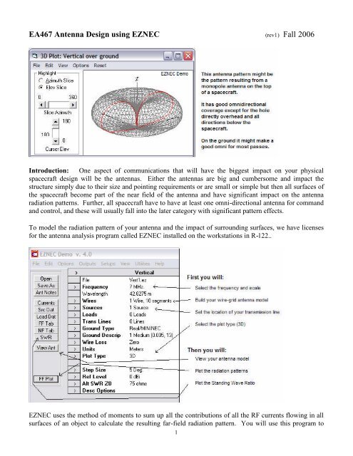
<strong>EA467</strong> <strong>Antenna</strong> <strong>Design</strong> <strong>using</strong> <strong>EZNEC</strong> (rev1) Fall 2006Introduction: One aspect of communications that will have the biggest impact on your physicalspacecraft design will be the antennas. Either the antennas are big and cumbersome and impact thestructure simply due to their size and pointing requirements or are small or simple but then all surfaces ofthe spacecraft become part of the near field of the antenna and have significant impact on the antennaradiation patterns. Further, all spacecraft have to have at least one omni-directional antenna for commandand control, and these will usually fall into the later category with significant pattern effects.To model the radiation pattern of your antenna and the impact of surrounding surfaces, we have licensesfor the antenna analysis program called <strong>EZNEC</strong> installed on the workstations in R-122..<strong>EZNEC</strong> uses the method of moments to sum up all the contributions of all the RF currents flowing in allsurfaces of an object to calculate the resulting far-field radiation pattern. You will use this program to1
explore the basic fundamentals of antenna patterns and gain and then will develop a project <strong>using</strong> it.Below is the <strong>EZNEC</strong> main control panel:CAUTIONS: In this lab, you will be opening certain model files to manipulate them.PLEASE make sure that you do not SAVE a modified file over the top of our standardfiles. Either change the name of the file or save it on the desktop.TEAMS: We only have 9 licensed workstations with <strong>EZNEC</strong> installed, so form teams of two studentsper workstation. Many of these exercises will take two people, since one will operate the progam and theother can best assist with a pencil and some engineering paper to make sketches and help compute X, Y, Zcoordinates for the wire models.CAPTURING IMAGES: To save <strong>EZNEC</strong> images for your report. Hit the Print-Scrn key, then open theWindows PAINT program, and hit paste. Then save the file and email it to yourself.<strong>Antenna</strong> Models: The model is made up of small lengths of wire with the sum of all their contributionsintegrated over space. This is called a wire grid model. To limit processing demands, the general rule isthat segments no larger than about 0.1 wavelength are sufficient to give a reasonably close approximationto reality. Unfortunately the software is limited to 500 segments and it is surprisingly easy to run out. Youwill use the WIRES tab to build your antenna model, and SOURCES to set the location of yourtransmission line feed point. The location of segments in the model are simply points in the X,Y,Z planes.Below left is a simple model of a monopole over a plane, and a more complex model of the 10 inch cubePCsat is shown on the right with a monopole whip antenna on the top.HINT: Be sure to have a few pages of engineering paper handy to help you sketch your wire model andhelp you decide on the coordinate system and point values.2
3D Pattern Plots: The result of the <strong>EZNEC</strong> calculations is a 3D plot of the antenna pattern that can beviewed and rotated in any angle as shown on the next page, or a 2D plot that contains a number ofnumeric results such as the maximum gain of the main lobe, and the 3 dB beamwidth as shown below:Part A: Labsat Monopole Pattern: The first element of this lab is to build a model of a LABsat with a530 MHz monopole antenna and take off-air measurements of its antenna pattern to compare itstheoretical pattern from with your measurements. The monopole should be 1/4 wavelength long at thatfrequency.1) Open the LABsat530.ez model and modify the “wire” that represents the monopole to the correctlength. Raise the model about 5 feet above ground. Use at least 10 segments in the monopolewire. Enter your source at the base of the wire where it attaches to the LABsat. Set plot type toazimuth. Leave the antenna as a free space model (do not use any ground for this part).2) Produce a far-field 2D elevation plot and save the image for your report. Do NOT save yourantenna model unless you give it a unique name, so that we do not destroy the originalLABsat530.ez model.3) Now add a real ground and see the effect of ground reflections on the antenna pattern.Post Lab: You will compare this antenna pattern to the pattern you will measure in the antenna lab.Part B: Helix <strong>Antenna</strong>s: To complete this part you will construct an <strong>EZNEC</strong> model of the Fleetsat helixwe used in the EA-204 lab and compare the predictions with the measurements you will make in the3
<strong>EA467</strong> <strong>Antenna</strong> lab. Start by loading the Dipole1.ez and change UNITS to inches so you can makemeasurements with a simple ruler.1) Under the WIRES tab, create a helix of the dimensions of our Fleetsat antenna. Set End-1 on theground plane pointing in the +Z direction Use 8 segments per turn and make the wire diameterabout 0.4”2) Add a perfect ground plane and then delete the original wire #1 which was the original dipole.Now set a source at the beginning of wire #1 where it is connected to the ground plane.3) Do and SWR plot of the antenna over the frequency from 220 to 320 MHz.4) Call up the various displays of the antenna, pattern plots and SWR and hit the Print-Scrn key andpaste the images into PAINT and save for your report.Part C. Manpack <strong>Antenna</strong>: The manpack antenna is a cross polarized pair of dipoles to optimizesatellite reception when the polarization is not known. For this lab, you will build your <strong>EZNEC</strong> antennamodel for only one of the dipoles since the two polarizations are independent of each other.1) Take measurements of the manpack antenna with a ruler so that you have the dimensions of boththe dipole, its height above its ground plane and the dimensions of the ground plane. Open theDipole1.ez as a starting point. Change the model by scaling it to 300 MHz and entering a wiregrid model of one of the dipoles and the ground plane. Make the dipole as two rectangles with asmall 2” short segment in between and place your source at the center of that short segment.2) Make the radials of the ground plane by making just one, and then use the RADIAL tool togenerate the rest. Remember to give them a meaningful thickness. Look at the wires table, andnow add in the additional circumference wire part of the ground plane.3) Produce both 2D and 3D plots and data for your report.Part D: Parabolic Dish <strong>Antenna</strong>s: One of the most common antenna types used for space applicationsis the parabola because it can be used over a variety of frequencies by only changing the feed system. Thefeed then is usually only a dipole in front of a small reflector to focus the energy into the dish. But sincethe largest structure of the dish acts as nothing more than a reflector to focus energy on the feed usuallyonly the pattern of the feed is modeled in programs like <strong>EZNEC</strong>, and then the gain calculated purely fromthe geometry. But for the purposes of this lab, we generated a wire grid model of the dish itself. To keep4
the number of segments below the 500 maximum, we only use a linear feed in one polarization, andtherefore we only need to model the dish in that one polarization. The holes in the dish are less than 0.1wavelength to keep within the rule of thumb.1) Open the file named “dish.ez”. View the antenna model and you will see that it is a very deepdish with the feed dipole deep inside. Normally dishes are flatter and have the dimensionswhere the focal point is .4 from the center of the dish compared to the diameter. As loaded, thefeed point is 3 inches from the dish. Look at the Far Field and 3D plot and then 2D plot andantenna gain.2) Using the WIRES tab, adjust the height of the feed dipole and see the effect on the gain andradiation pattern. See if you can find the location of the highest gain.3) Adjust the length and thickness of the feed dipole to get the lowest SWR at 2400 MHz andcomment for your report.Part E. Omni <strong>Antenna</strong>s, Spacecraft and Multipath: All spacecraft need omni antennas, but largespacecraft usually need one on opposite ends of the spacecraft to assure spherical coverage. But wheneveryou have two antennas connected to the same system, if they have overlapping coverage, there will bemultiple lobes in the antenna pattern due to the mutual constructive and destructive interference of thewaves in the overlapping areas. This lobing effect is called “multipath” which causes these phasedifferences. This effect occurs in all RF systems when there are multiple reflections and different pathlengths from one antenna to any point. Follow the instructions below:5
Part F. Personal <strong>Antenna</strong> <strong>Design</strong>: For this portion of this lab, you will design an antenna reflectorsystem and model it on your own. You will build the wire model, and obtain your best gain, and alsopreferably a low SWR at your operating frequency. You only need to do one of the following suggestedprojects:a) A corner reflector of at least 20 rods to place behind your personal 802.11 Wireless Access Pointdipole antenna (2400 MHz) to attempt to give gain in one direction and give you some security inother directions. See how much gain you can achieve. Make your corner reflector at 90 degreeswith rods spaced closer than 0.1 wavelength. Iteratively find the optimum location for the feedalong the centerline to get the best gain.b) A pocket corner reflector for your cell phone (as in (a)), but designed for the 800 MHz cell phoneband or your PCA phone at 1800 MHz.c) Model the typical Cell phone gain antenna you see on cars, which is a 1/4 wave monopole on aground plane, but then over the top of it is a full size dipole fed in phase. In real antennas, this isaccomplished with a coil to give a phase delay, but your model will simply use a source at the baseof the monopole and another source in the middle of the raised dipole. What is the optimumspacing for the Dipole above the monopole?Post Lab: You will be <strong>using</strong> many of the elements of this lab for comparison with the values obtained inthe <strong>Antenna</strong> Lab next period. You will write a combined formal lab report to cover all the material inboth labs.. Compare actual results to theoretical or those results from the antenna modeling program toshow how theory meets practice. The lessons learned here will be very important to you in your satellitedesign.6