COMBAT ® Tubular Unit Heater Installation ... - Roberts Gordon
COMBAT ® Tubular Unit Heater Installation ... - Roberts Gordon
COMBAT ® Tubular Unit Heater Installation ... - Roberts Gordon
- No tags were found...

Create successful ePaper yourself
Turn your PDF publications into a flip-book with our unique Google optimized e-Paper software.
Product ApprovalROBERTS GORDON ® appliances have been tested and CE certified as complying with the essentialrequirements of the Gas Appliance Directive, the Low Voltage Directive, the ElectromagneticCompatibility Directive and the Machinery Directive for use on natural gas and LPG when installed,commissioned and maintained in accordance with these instructions.These instructions refer to appliances designed to operate in the European Union.Appliances designed for other countries (Non-European Union) are available on request.This appliance must be installed in accordance with the local and national codes in force and usedonly in a sufficiently ventilated space, as specified in these instructions.Before installation, check that the local gas distribution systems, nature of gas and pressure, andadjustment of the appliance are compatible.1 of 51
<strong>COMBAT</strong> ® CTU UNIT HEATERS INSTALLATION OPERATION AND SERVICE MANUALSECTION 2: INSTALLER RESPONSIBILITY• To install the heater, as well as the gas and electricalsupplies, in accordance with applicablespecifications and regulations. <strong>Roberts</strong>-<strong>Gordon</strong>recommends the installer contact a localauthority, building inspector or insurancecompany for guidance.• To use the information given in the manualtogether with the local and national regulationsto perform the installation.• To install the heater in accordance with theclearances to combustibles of this heater.• To apply all needed materials not suppliedas standard equipment.• To plan location of supports, flues and airintakes.• To provide access to burners for servicing.• To provide the owner with a copy of thisinstallation, commissioning, operation andservice manual.• To never use heater as support for ladder orother access equipment and never hang orsuspend anything from heater.• To ensure that there is sufficient ventilation in thearea to comply with the requirements ofall relevant local and national regulations.• To safely and adequately install heater usingmaterials with a minimal working load of 33 kg.• To ensure the heater is placed in an approvedapplication.2.1 Laminated Wall PlateA laminated wall plate is available for the heater as apermanent reminder of the safety instructions andthe importance of the required clearances tocombustibles. Affix theplate by peeling off thebacking of the adhesive strips on the rear surfaceand position the plate on a wall near the heater (e.g.thermostat or ROBERTS GORDON ® Controller).A copy of the wall plate (P/N 91040028) is illustratedon the back cover. Know your model number andinstalled configuration. Model number and installedconfiguration are found on the heater and in the<strong>Installation</strong>, Operation and Service Manual.2.2 Corrosive ChemicalsCAUTIONProduct Damage HazardDo not use heater in area containingcorrosive chemicals.Refer to appropriate Material Safety DataSheets (MSDS).Failure to follow these instructions can resultin product damage.<strong>Roberts</strong>-<strong>Gordon</strong> cannot be responsible for ensuringthat all appropriate safety measures are undertakenprior to installation; this is entirely the responsibilityof the installer. It is essential that the contractor, thesub-contractor, or the owner identifies the presenceof combustible materials, corrosive chemicals orhalogenated hydrocarbons* anywhere in thepremises.* Halogenated Hydrocarbons are a family of chemicalcompounds characterized by the presence of halogenelements (fluorine, chlorine, bromine, etc.). These compoundsare frequently used in refrigerants, cleaningagents, solvents, etc. If these compounds enter the airsupply of the burner, the lifespan of the heater componentswill be greatly reduced. Warranty will be invalid ifthe heater is exposed to halogenated hydrocarbons.2.3 National Standards and ApplicableRegulationsAll appliances must be installed in accordance withthe latest revision of applicable standards and localand national regulations. This refers also to theelectric, gas and venting installation. Note:Additional standards for installations in publicgarages, aircraft hangars, etc. may be applicable.4 of 51
SECTION 3: CLEARANCES TO COMBUSTIBLESWARNINGFire HazardKeep all flammable objects, liquids andvapours the minimum required clearances tocombustibles away from heater.Some objects will catch fire or explode whenplaced close to heater.Failure to follow these instructions can resultin death, injury or property damage.3.1 Required Clearances to CombustiblesClearances are the required distances thatcombustible objects must be away from the heaterto prevent fire hazards. Caution should be usedwhen running the system near combustibles.Combustibles are materials, which may catch on fireand include common items such as wood, paper,rubber, fabric, etc. Maintain clearances tocombustibles at all times for safety.Clearances around the heater and flue must be asindicated on Page 6, Figure 3 to ensure access forservicing, and correct operation. If clearances tocombustibles are not indicated, then installationclearances apply.Check the clearances on each burner for the modelheater being installed to make sure the product issuitable for your application and the clearances aremaintained. Read and follow the safety guidelinesbelow:• Keep petrol or other combustible materialsincluding flammable objects, liquids, dust orvapours away from this heater or any other appliance.• The stated clearances to combustibles representsa surface temperature of 32°C (90° F)above room temperature. Building materials witha low heat tolerance (such as plastics, vinyl siding,canvas, tri-ply, etc) may be subject to degradationat lower temperatures. It is the installer’sresponsibility to assure that adjacent materialsare protected from degradation.• Maintain clearances from heat sensitive equipmentand workstations.• Maintain clearances from vehicles parked belowthe heater.• Maintain clearances from swinging and overheaddoors, overhead cranes, vehicle lifts, parti-SECTION 3: CLEARANCES TO COMBUSTIBLEStions, storage racks, hoists, buildingconstruction, etc.• In locations used for the storage of combustiblematerials, signs must be posted to specify themaximum permissible stacking height to maintainrequired clearances from the heater to thecombustibles. Signs must be posted adjacent tothe heater thermostat. In the absence of a thermostat,signs must be posted in a conspicuouslocation.• Consult local Building Inspector, Fire InsuranceCarrier or other authorities for approval of proposedinstallation when there is a possibility ofexposure to combustible airborne materials orvapours.• Hang heater in accordance to the minimumsuspension requirements on Page 12, Section 6and Page 13, Figure 4 through Page 14, Figure6.• Affix the tag on a wall near the heater.5 of 51
<strong>COMBAT</strong> ® CTU UNIT HEATERS INSTALLATION OPERATION AND SERVICE MANUALFigure 3: <strong>Installation</strong> Clearances and Clearances to Combustibles<strong>Installation</strong> ClearancesClearances to CombustiblesRoof TerminalAirIntake15 cm15 cmWallTerminalFlue60 cm3 m50 cm 50 cm**30 cm2.5 - 3.5 m** <strong>Heater</strong>s may be mounted at a higher level ifdestratification fans and/or turn down nozzles areinstalled.The heater must always be installed at least 2.5 m above the floor.The flue pipe must have clearance from combustibles by 5 cm.**80 cm is necessary to service heater.If installed at low levels where individuals can come in contact with hot heat exchanger components,adequate guarding must be provided.All distances are minimum clearance requirements for service access, air flow and safety.6 of 51
SECTION 4: CRITICAL CONSIDERATIONS4.1 VentilationWARNING4.3 Electrical SupplySECTION 4: CRITICAL CONSIDERATIONSDANGERIt is important to ensure that there is adequate aircirculation around the heater to supply air forcombustion, ventilation and distribution inaccordance with local and national codes.4.2 Gas SupplyCarbon Monoxide Hazard<strong>Heater</strong>s may be installed vented or unvented.Vented heaters must be vented outdoors.Unvented heaters must be installed inbuildings with ventilation rates as persection 7.Failure to follow these instructions can resultin death or injury.Electrical Shock HazardDisconnect electric before service.<strong>Heater</strong> must be properly grounded.Failure to follow these instructions can resultin death or electrical shock.A permanent 230 V 50 Hz electrical supply isrequired at the main electrical terminals. The heateralso requires suitable energy controls in accordancewith Section 11.4.4 FlueChoose heater siting to allow for the proper locationof the flue. Each heater must be fitted with anindividual and correctly sized sealed flue system(See Section 7).No other appliance may be connected to the flue.For room sealed installation, the air intake must bethe same size sealed system and the flue/air intakemust terminate at an approved concentric wall orroof terminal.It is important that the gas supply pipe is sizedcorrectly to provide the inlet pressure as stated onthe heater data plate. The gas supply pipe andelectrical connections must not support any of theheater's weight.7 of 51
<strong>COMBAT</strong> ® CTU UNIT HEATERS INSTALLATION OPERATION AND SERVICE MANUALSECTION 5: SPECIFICATIONS5.1 CTUA77Top View <strong>Heater</strong> must be supportedat these points from aboveor below.E C DSupport492Centers4 x M10 Captive Nuts ProvidedJRear ViewEnd View646ZAir IntakeFGHFlueBLockout ResetGasSupplyElectricalCable Entry168Dimension Data - CTUA (All Models)AABCDEFGHJZModel 22 30 35 40 50 60 75 90 100 115Widthmm 1075 1075 1075 1075 1075 1075 1327 1327 1327 1327(in) (42.3) (42.3) (42.3) (42.3) (42.3) (42.3) (52.3) (52.3) (52.3) (52.3)Heightmm 610 610 610 610 895 895 1100 1100 1345(in) (24) (24) (24) (24) (35.2) (35.2) (43.3) (43.3) (53)1345(53)Support Spacingmm 450 450 450 450 450 450 627 627 627 627(in) (17.7) (17.7) (17.7) (17.7) (17.7) (17.7) (24.7) (24.7) (24.7) (24.7)Support Spacingmm 312 312 312 312 312 312 312 312 312 312(in) (12.3) (12.3) (12.3) (12.3) (12.3) (12.3) (12.3) (12.3) (12.3) (12.3)Support Spacingmm 315 315 315 315 315 315 388 388 388 388(in) (12.4) (12.4) (12.4) (12.4) (12.4) (12.4) (15.3) (15.3) (15.3) (15.3)Centre of Fluemm 240 240 240 240 430 430 346 346 537 537(in) (9.5) (9.5) (9.5) (9.5) (16.9) (16.9) (13.6) (13.6) (21.1) (21.1)Centre of Flue/Air Intakemm 140 140 140 140 140 140 225 225 225 225(in) (5.5) (5.5) (5.5) (5.5) (5.5) (5.5) (8.9) (8.9) (8.9) (8.9)Position of Fluemm 218 218 218 218 211 211 260 260 260 260(in) (8.6) (8.6) (8.6) (8.6) (8.3) (8.3) (10.2) (10.2) (10.2) (10.2)Gas Inlet Positionmm 150 150 150 150 150 150 220 220 220 220(in) (5.9) (5.9) (5.9) (5.9) (5.9) (5.9) (8.7) (8.7) (8.7) (8.7)Lengthmm 756 756 756 756 806 806 756 756 806 806(in) (29.8) (29.8) (29.8) (29.8) (31.8) (31.8) (29.8) (29.8) (31.8) (31.8)Flue/Air Intake Pipe Sizemm Ø 100 100 100 100 100 100(in) Ø (3.9) (3.9) (3.9) (3.9) (3.9) (3.9)130(5.1)130(5.1)130(5.1)130(5.1)Weight kg 84 84 88 92 115 122 160 169 194 2038 of 51
<strong>COMBAT</strong> ® CTU UNIT HEATERS INSTALLATION OPERATION AND SERVICE MANUAL5.3 General Technical Data TableCTUA With Axial FanModel CTU-22 CTU-30 CTU-35 CTU-40 CTU-50 CTU-60 CTU-75 CTU-90 CTU-100 CTU-115Total Electrical Load W 210 210 210 210 415 415 510 510 745 745Run Current A 1.0 1.0 1.0 1.0 1.72 1.72 1.9 1.9 3.2 3.2Start Current A 1.4 1.4 1.4 1.4 2.4 2.4 2.8 2.8 4.5 4.5Air Flow m 3 /h 3800 4000 4000 4000 5500 5500 7500 7500 11,000 11,000Sound Pressure Levelat 3 m[NR]dB(A)[51]56[51]56Electrical load at 230 V 50 Hz measured by calculating from total run current of appliance.[51]56* Do not exceed the maximum length of flue stated or heater may not operate properly. Reduce themaximum length stated by 1 m for each 90° bend installed.**If minimum air flow requirements are not met, then temperature limit devices will shut down the heater.[51]56[52.1]57.1CTUB with Centrifugal Fan and CTUC Range with Centrifugal Fan and Duct InletTotal Electrical Load W 550 550 550 550 1100 1100 1100 1100 1650 1650Normal Run Current A 4.6 4.6 4.6 4.6 11.0 11.0 11.0 11.0 15.6 15.6Normal Start Current A 9.0 9.0 9.0 9.0 13.5 13.5 13.5 13.5 19.2 19.2Normal Speed Medium Medium Medium Medium Medium Medium Medium Medium Medium MediumHigh Run Current A 5.5 5.5 5.5 5.5 14.0 14.0 14.0 14.0 21.0 21.0High Start Current A 13.6 13.6 13.6 13.6 17.2 17.2 17.2 17.2 25.8 25.8Air Flow m 3 /h 3300 3300 3300 3300 5500 5500 6400 6400 9400 9400Sound Pressure Levelat 3 m[NR]dB(A)CTUD Duct <strong>Heater</strong> with No Fan[59]59.5[59]59.5[59]59.5[59]59.5**Minimun Air FlowRequired m 3 /h 3300 3300 3300 3300 5500 5500 6400 6400 9400 9400Pressure Loss AcrossHeat Exchanger Pa 30 30 30 30 30 30 30 30 30 30Flue and AIr IntakeFlue and Air IntakeSize mm Ø 100 100 100 100 100 100 130 130 130 130*Maximum StraightFlue/Air Intake m 7 8 8 10 13 15 15 17 20 20[61]61.5[52.1]57.1[61]61.5[52.3]57.3[62]61.8[52.3]57.3[62]61.8[52.3]57.3[63]64.2[52.3]57.3[63]64.210 of 51
SECTION 5: SPECIFICATIONS5.4 Technical Data TableAppliance Category II 2H/L 3B/PModel CTU-22 CTU-30 CTU-35 CTU-40 CTU-50 CTU-60 CTU-75 CTU-90 CTU-100 CTU-115Heat InputGross CVkW(Btu/h) x (1000)2792.03390.03991.442.990.691.892.77092.09590.611191.092.291.513491.7Heat InputNet CVkW(Btu/h) x (1000)2484301023511943147551896321586292100341107365121414ApproximateHeat OutputkW(Btu/h) x (1000)2275289632109401365117458198792709231498334111379Thermostat Limit ThermodiscCTUA, B/C, D °C 75 75 75 75 75 75 75 75 75 75Natural Gas (G20) Data - Inlet Pressure 20 mbar (7.8 in WG) Min. 17 mbar (6.8 in WG) Max. 25 mbar (10 in WG)Burner Pressure mbar 8.3 8.7 8.5 9.4 9.3 8.5 6.1 6.0 6.2 6.3Gas Ratem 3 /hft 3 /h2.6923.21123.71314.51605.82066.62349.031910.537111.339812.8451Natural Gas (G25) Data - Inlet Pressure 25 mbar (10 in WG) Min. 20 mbar (7.8 in WG) Max. 30 mbar (12 in WG)Burner Pressure mbar 12.2 12.7 12.5 14.0 13.6 13.2 9.2 9.3 9.2 10.2Gas Ratem 3 /hft 3 /h3.031073.331174.311524.781696.142176.982479.4933511.0639111.8641913.43474LPG Gas Propane (G31) Data - Inlet Pressure 37 mbar (14.6 WG) Min. 25 mbar (10 in WG) Max. 45 mbar (18 in WG)Alternative where permitted 50 mbar (20 in WG) Min. 42.5 bar (17 in WG) Max. 57.5 mbar (23 in WG)Burner Pressure mbar 26.6 24.9 25.4 25.9 25.6 26.8 25.6 27.3 25.3 25.9Gas Ratem 3 /hkg 3 /hliquid/h1.011.873.71.232.284.51.482.755.41.773.276.42.274.218.32.584.799.43.516.5012.84.097.5814.94.398.1316.04.979.2118.1LPG Gas Butane (G30) Data - Inlet Pressure 29 mbar (11,4 in WG) Min. 20 mbar (7.8 in WG) Max. 35 mbar (13.8 WG)Burner Pressure mbar 18.9 17.4 17.8 19.5 18.4 19.0 18.3 19.4 18.3 18.7Gas Ratem 3 /hkg 3 /hliquid/h0.761.863.20.932.274.01.062.594.51.343.265.71.724.197.31.954.778.32.656.4711.33.097.5513.23.328.0914.13.759.1716.0Gas ConnectionCTUA, B/C, D R - 1/2" R - 1/2" R - 1/2" R - 1/2" R - 1/2" R - 1/2" R - 3/4" R - 3/4" R - 3/4" R - 3/4"Gas rates corrected to standard conditions 1013.25 mbar 15° C.11 of 51
<strong>COMBAT</strong> ® CTU UNIT HEATERS INSTALLATION OPERATION AND SERVICE MANUALSECTION 6: HEATER INSTALLATION6.1 General<strong>Heater</strong>s are designed for installation above 2.5 m.These heaters must be installed within the heatedspace. Duct delivery systems are not permitted withaxial fans. When handling or supporting the heaterfrom below, ensure that the weight is taken at thesupport points.6.5 Suspension and Shelf MountingWARNING6.2 Basic InformationCTU heaters have automatic ignition burners forON/OFF operation only.6.3 Location and SuspensionAll models:• Must be installed indoors.• Must be installed in a level position.• May be mounted on a shelf of non-combustiblematerial. (See Page 13, Figure 5, Page 14, Figure6 and the Dimension Data Tables on Page 8,Section 5.1 and Page 9, Section 5.2 for supportpoints).• May be suspended from above (See Page 13,Figure 4) or from wall brackets of sufficientstrength to support the heater as listed in theDimension Data Tables on Page 8, Section 5.1and Page 9, Section 5.2. Drop rods must be aminimum of 10 mm diameter mild steel. Foursuspension points (M10 nuts) are located on topof the heater.• Must be installed in a manner which allows thehinged door to be fully opened to provide accessto all serviceable components.6.4 HandlingAll CTU heaters are supplied secured to a woodenpallet and shrink wrapped. Use the pallet to supportthe heater during handling and installation. Whenhandling or supporting the heater from below,ensure that the weight is taken at the support points.Crush HazardUse 10 mm steel drop rod minimum.Failure of the supports can result in death,injury or property damage.For typical suspension See Page 13, Figure 4.The gas or electrical supply lines must not be usedto support the heater.Do not locate the gas or electrical supply linesdirectly over the path of the flue products from theheater.The heater must be installed in a location that isreadily accessible for servicing.The heater must be installed in accordance withclearances to combustibles as indicated on the walltag and in this manual.6.6 Wall MountingFor typical suspension, See Page 14, Figure 6. Wallmounted heaters blowing parallel to the wall canonly be installed with the service door away from thewall.The wall mounting brackets must be attached to asuitable wall using all mounting holes. Screw sizesless than 9.0 mm (3/8") may not be used. In orderfor the wall mounting brackets to adequately carrythe weight of the heater, it must be installedaccording to best building practices.12 of 51
Figure 4: Suspension MethodsSECTION 6: HEATER INSTALLATIONUnistrutChannel NutInsure all suspension hardwareis torqued to a minimumof 27 Nm (20 ft lbs)WasherNut10 mmSteelDrop RodCone PointSet PinWindowClamp10 mmSteelDrop RodNutWasherUnistrutRivNutSupport PointsFigure 5: Shelf-Mounting MethodsShelf MountingBracketsExisting cabinet screws must be re-used.13 of 51
<strong>COMBAT</strong> ® CTU UNIT HEATERS INSTALLATION OPERATION AND SERVICE MANUALFigure 6: Wall Shelf Mounting and SuspensionWall Shelf MountingWall Suspension MountingShelfMountingBrackets(Fasten toWall MountingBracket)3/8" FastenersWall MountingBracket Arm(Right & Left)Wall MountingBracket DiagonalWall MountingBracket Vertical5/16" x 3 1/2" Bolt5/16" Flat Washer5/16" Locknut with Nylon InsertTorque to 40 in lb (4.5 Nm).Hardware to construct mounting bracket assembly not provided by <strong>Roberts</strong>-<strong>Gordon</strong>.14 of 51
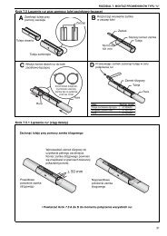
SECTION 7: FLUE INSTALLATION7.1 Flue <strong>Installation</strong>WARNINGCarbon Monoxide Hazard<strong>Heater</strong>s installed unvented must be interlockedwith sufficient building exhaust.<strong>Heater</strong>s must be installed according to theinstallation manual.Failure to follow these instructions can resultin death or injury.WARNINGSECTION 7: FLUE INSTALLATIONPage 16, Figure 9. The joints between the flueterminal and the roof or wall must be properlysealed. If the flue passes through a wall or ceiling ofcombustible material, it must be enclosed by asleeve of non-combustible material and beseparated from the sleeve by at least a 25 mm airgap.Flues and air intakes must be adequatelysupported so that the heater does not bear theweight of the pipes.For flue termination See Page 15, Figure 7 throughPage 16, Figure 9.7.2 Type C 12 , C 32 & C 62 ApplianceRoom Sealed.The heaters are designed to be installed as roomsealed appliances. The flue and air intake are run asseparate pipes to the special concentric wall or roofterminal. See Page 16, Figure 9. The wire mesh befitted inside the fresh air adapter on the heater andmust be removed prior to installation.Fire HazardKeep all flammable objects, liquids andvapours the minimum required clearances tocombustibles away from heater.Some objects will catch fire or explode whenplaced close to heater.Failure to follow these instructions can resultin death, injury or property damage.WARNING7.3 Type B 22 ApplianceThe flue must terminate outside the building and befitted with a low resistance terminal.See Page 15, Figure 7 through Page 16, Figure 8.Figure 7: Flue and Roof DetailFlueTerminalMasterflashSoaker Flashingor Rain Collar.RoofCut/Pinch HazardWear protective gear during installation,operation and service.Edges are sharp.Failure to follow these instructions can resultin injury.The flue must terminate outside of the building.Flues and air intakes must be a fully sealed systemand correctly sized for the model. Flues should beassembled as detailed on Page 15, Figure 7 through25 mm Air Gap toCombustible MaterialMetal SleeveFlue15 of 51
<strong>COMBAT</strong> ® CTU UNIT HEATERS INSTALLATION OPERATION AND SERVICE MANUALFigure 8: Vertical and Horizontal Flue Termination - Type B 22 ApplianceRoof TerminalMasterflashFlueAir IntakeTerminal CoverVerticalOptionMetal Sleeve(25 mm air gap toCombustible Material)90°BendFlueHorizontalOptionMasterflashWallTerminalFigure 9: Vertical and Horizontal Flue Termination - Type C 12 C 32 & C 62 AppliancesRoof TerminalPlastic CupMasterflashModelConcentric Flue Diameter22-60 Cover (100mm) 150mm75-115 Cover (130mm) 200mmManifoldAir IntakeVerticalOptionAir IntakeFlueHorizontalOptionFlue90° BendManifoldMax wall thickness335 mmWallTerminalWallPlate End ViewThe minimumgap must bepositioned at bottom16 of 51
SECTION 8: AIR SUPPLYSECTION 8: AIR SUPPLY8.1 Room Sealed <strong>Installation</strong>When installed as a room sealed heater, the air forcombustion is drawn in from outside the building. Itis important to ensure that there is adequateventilation to provide air for the distribution fan/s.8.2 Open Flued <strong>Installation</strong>It is important to ensure that there is adequate airsupply at all times for both combustion and heatingrequirements in accordance with local and nationalcodes. When installed in this mode, the air supply tothe heater must also be fitted with a low resistanceterminal to prevent the ingress of debris. See Page16, Figure 8.8.2.1 <strong>Heater</strong>s Installed Within the Heated SpaceWhere the volume of the heated space is greaterthan 4.7 m 3 per kilowatt of total rated heat input andthe air change rate is at least 0.5/h, additional highand low level ventilation will not be required.For a building having an air change rate less than0.5/h, ventilation will be necessary in accordancewith local and national codes. Ventilation direct tooutside must be provided as follows:• <strong>Heater</strong>s up to 70 kW heat input: 5.0 cm 2 per kWof rated heat input• <strong>Heater</strong>s above 70 kW heat input: 350 cm 2 + 2.5cm 2 per kW of rated heat input above 70 kW8.3 Building VentilationWhere ventilation is required, air must be taken froman outside point where it is not likely to becontaminated or obstructed.Where natural ventilation is used, suitable ventilationwith outside air at low level must be provided inaccordance with Section 8.2.1 and local andnational codes.Where mechanical ventilation is used, extract ratemust be 5% - 10% less than the inlet rate. Themechanical ventilation must be interlocked with theburner on the CTU heater.8.4 Isolated Equipment RoomsVentilation must prevent the isolated equipmentroom temperature from exceeding 32° C as well asprevent any negative air pressure within the room.See Page 17, Figure 10. Any isolated equipmentroom containing air heaters will require permanentair vents direct to outside air in compliance with localcodes.Where natural ventilation is used, suitablepermanent openings at low and high level,communicating directly with the outside air, must beprovided.Where mechanical ventilation is used, extract ratemust be 5% - 10% less than the inlet rate. Themechanical ventilation must be interlocked with theburner on the CTU heater.Figure 10: <strong>Heater</strong>s Installed in Isolated Equipment RoomsManifoldHigh LevelVentilationAir IntakeFlueDuct DistributionSystem orDischarge toHeated SpaceReturn Air Ductfrom HeatedSpace or FreshAir from OutsideMax Temperature 32° CRoom Air Pressure Must Not be Negative.Low LevelVentilationWallOutsideWall17 of 51
<strong>COMBAT</strong> ® CTU UNIT HEATERS INSTALLATION OPERATION AND SERVICE MANUALSECTION 9: OPTIONAL HEATER CONFIGURATIONS9.1 Distribution Duct Work for CTUB, CTUC andCTUD <strong>Heater</strong>sCTUC heaters have the fans enclosed so that theheater may be connected to inlet ducting.CTUD heaters are supplied with inlet and outlet ductspigots for mounting the heater into a customerdesigned duct system for use with an external fansystem.It is recommended that flexible duct connectors areused to reduce duct born noises.When installing CTUD heaters onto ducting forcethe fan to run.Do not rely on the fan thermostat to turn it on.Any such device must be in parallel with the fanthermostat so that the fan run-on operation will stilloperate.Contact <strong>Roberts</strong>-<strong>Gordon</strong> Europe Ltd. DesignDepartment for recommendations regardingduct resistance and design. Tel: +44 (0) 121 50677009.1.1 CTUD <strong>Heater</strong>sFor CTUD heaters, it is essential that the airflow inthe duct system is at least that specified in the DataSheet on Page 9, Section 5.2 and in the correctdirection across the heat exchanger as indicated bythe arrow on the heater. Higher air flows arepermitted, but will cause a lower exiting airtemperature. It is recommended that the fan ispositioned to blow the air through the heatexchanger.The duct must be designed as described on Page18, Section 9.1 and Figure 11 to ensure that there isa homogenous air flow across the whole of the heatexchanger.Failure to provide a suitable air flow properlydistributed across the heat exchanger will reduce thelife of the heat exchanger.The fan motor, or its control, must contain a methodof overload protection. When installed remote fromthe heater, the fan must be supplied via a localelectrical isolator positioned and properly labeled toprevent inadvertent operation.Figure 11: DuctingNOTE: Duct size will be full size of inlet and outlet.All joints between the heater and duct work should bemade as air tight as possible.Minimum-TwiceDimension“X”Dimension“X”Airflow IndicatorMinimum-TwiceDimension“X”DuctingFlexible FlangeDucting18 of 51
SECTION 10: GAS PIPE WORKSECTION 10: GAS PIPE WORK• The gas supply pipe is adequately sized to carrythe total volume of gas for the completeinstallation.• An isolating valve and union connection shouldbe used and fitted into the supply adjacent to theheater.• For suspended heaters, use an approved metalflexible connection between the isolating valveand the heater. To reduce pressure loss, useone pipe size larger than the heater gasconnection.IMPORTANT - The complete installation must bepurged and tested for gas soundness in accordancewith local and national regulations.WARNING• Check the pipe and tubing ends for leaksbefore placing heating equipment into service.When checking for gas leaks, use asoap and water solution; never use an openflameExplosion HazardLeak test all components of gas pipe workbefore operation.Gas can leak if pipe work is not installedproperly.Do not high pressure test gas pipe work withheater connected.Failure to follow these instructions can resultin death, injury or property damage.It is important that the gas supply pipe and theelectrical connections do not support any of theheater’s weight.A gas meter is connected to the service pipe by thegas supply company. An existing meter should bechecked, preferably by the gas supplier, to ensurethat the meter is adequate for the rate of gas supplyrequired.<strong>Installation</strong> pipes must be fitted in accordance withlocal and national regulations. Pipe work from themeter to the heater(s) must be of adequate size.10.1 ConnectionsConnect the heater to the gas supply ensuring thatthe final connections are as follows:• Gas supply pipe work is run in medium or heavygauge tubing in compliance with local andnational regulations.19 of 51
<strong>COMBAT</strong> ® CTU UNIT HEATERS INSTALLATION OPERATION AND SERVICE MANUALFigure 12: Gas Connection with Stainless Steel Flex Connector20 of 51
SECTION 11: WIRING AND ELECTRICAL INFORMATIONSECTION 11: WIRING AND ELECTRICAL INFORMATIONDANGERElectrical Shock HazardDisconnect electric before service.<strong>Heater</strong> must be properly grounded.Failure to follow these instructions can resultin death or electrical shock.11.1 Electrical SupplyAll heaters need a constant 230 V 50 Hz singlephase supply connected to terminals L, N & Earth.Polarity "L & N" must be correct. The voltagebetween neutral and earth should be 0 and neverexceed 15 volts.All heaters and controls must be correctly earthed.All external wiring must conform to "HAR"(harmonised wiring code) HOSVV-F (PolyvinylChloride Cord).External controls must have the same constant230 V 50 Hz supply.An isolator with a contact separation of at least3 mm on all poles must be installed adjacent to, butnot attached to, the heater to disconnect all suppliesto the heater and any remote control.The final connection to the heater should be madeby flexible cable or conduit to the main terminalblock on the inside of the heater using 1 mm 2 cableon all models.11.2 Remote ControlsThe heater is designed to be operated by controlsinstalled remote from the heater. See Page 22,Section 11.3. through Page 23, Section 11.4.11.2.1 Burner Controls (Thermostat)Controls to operate the burner must be voltage freecontacts connected between terminals 2 & 3 of themain terminal block.11.2.2 Positioning Room Thermostats orROBERTS GORDON ® ControlA room thermostat or ROBERTS GORDON ®control should be mounted on a wall or column at aheight of approximately 1.5 metres from the floor tomeasure the ambient temperature. It should be clearof both cold draughts and the direct path of warm airfrom the heater.11.2.3 Remote Frost ThermostatWhen required, connect to terminals 2 and 3 in themain terminal block.Locate within the heated space adjacent to the mostvulnerable equipment that requires protection.See Page 22, Section 11.3 through Page 23,Section 11.4.11.2.4 Remote Fan ControlsThe fan will operate automatically providing there isa constant 230 V supply to the main terminals.A switch or control wired between terminals L & 1 inthe terminal block will allow external control of thefan(s).The fan may be controlled to operate continuouslyfrom an external control, with the burner cycling onand off, providing that the fan run-on at close downis not impaired.Models............................................ Fuse SizeCTUA (All Models) ........................................... 5 ACTUB & CTUC (Models 22-50)...................... 10 ACTUB & CTUC (Models 75 - 115).................. 20 ACTUD heaters must have the external fan, or itscontrol connected to Terminal 1 so that the fan runonfunction at close down operates correctly.21 of 51
<strong>COMBAT</strong> ® CTU UNIT HEATERS INSTALLATION OPERATION AND SERVICE MANUAL11.3 CTUA Wiring Diagram (Models 22-60)NOTE:If any of the original wire supplied withthe heater must be replaced, it must bereplaced with wiring material having atemperature rating of at least 105° Cand 600 volts.22 of 51
11.4 CTUA Wiring Diagram (Models 75-115)SECTION 11: WIRING AND ELECTRICAL INFORMATIONNOTE:If any of the original wire supplied withthe heater must be replaced, it must bereplaced with wiring material having atemperature rating of at least 105° Cand 600 volts.23 of 51
<strong>COMBAT</strong> ® CTU UNIT HEATERS INSTALLATION OPERATION AND SERVICE MANUAL11.5 CTUB/C Wiring Diagram (Models 22-40)NOTE:Unused speed setting wires for thecentrifugal fan must be isolated andinsulated. If any of the original wiresupplied with the heater must bereplaced, it must be replaced withwiring material having a temperaturerating of at least 105° C and 600 volts.24 of 51
11.6 CTUB/C Wiring Diagram (Models 50-60)SECTION 11: WIRING AND ELECTRICAL INFORMATIONNOTE:Unused speed setting wires for thecentrifugal fan must be isolated andinsulated. If any of the original wiresupplied with the heater must bereplaced, it must be replaced withwiring material having a temperaturerating of at least 105° C and 600 volts.25 of 51
<strong>COMBAT</strong> ® CTU UNIT HEATERS INSTALLATION OPERATION AND SERVICE MANUAL11.7 CTUB/C Wiring Diagram (Models 75-115)NOTE:Unused speed setting wires for thecentrifugal fan must be isolated andinsulated. If any of the original wiresupplied with the heater must bereplaced, it must be replaced withwiring material having a temperaturerating of at least 105° C and 600 volts.26 of 51
11.8 CTUD Wiring Diagram (Models 22-60)SECTION 11: WIRING AND ELECTRICAL INFORMATIONNOTE:For external fan wiring,See Page 29, Section 11.10.If any of the original wire supplied with theheater must be replaced, it must be replacedwith wiring material having a temperaturerating of at least 105° C and 600 volts.27 of 51
<strong>COMBAT</strong> ® CTU UNIT HEATERS INSTALLATION OPERATION AND SERVICE MANUAL11.9 CTUD Wiring Diagram (Models 75-115)NOTE:For external fan wiring,See Page 29, Section 11.10.If any of the original wire supplied with theheater must be replaced, it must be replacedwith wiring material having a temperaturerating of at least 105° C and 600 volts.28 of 51
SECTION 11: WIRING AND ELECTRICAL INFORMATION11.10 CTUD External Motor Alternative Wiring & Optional Thermostat/Time Switch29 of 51
<strong>COMBAT</strong> ® CTU UNIT HEATERS INSTALLATION OPERATION AND SERVICE MANUALSECTION 12: COMMISSIONINGDANGERWARNINGElectrical Shock HazardDisconnect electricbefore service.More than onedisconnect switch maybe required todisconnect electric fromheater.Explosion HazardTurn off gas supply toheater before service.Burn HazardAllow heater to coolbefore service.Tubing may still be hotafter operation.Cut/Pinch HazardWear protective gearduring installation,operation and service.Edges are sharp.<strong>Heater</strong> must beconnected to a properlygrounded electricalsource.Failure to follow these instructions can result in death, electric shock, injury or property damage.Gas Fired <strong>Heater</strong><strong>Installation</strong> Code and Annual Inspections:All installation and service of ROBERTS GORDON ®equipment must be performed by a contractorqualified in the installation and service of equipmentsold and supplied by <strong>Roberts</strong>-<strong>Gordon</strong> and conformto all requirements set forth in the ROBERTSGORDON ® manuals and all applicablegovernmental authorities pertaining to theinstallation, service and operation of the equipment.To help facilitate optimum performance and safety,<strong>Roberts</strong>-<strong>Gordon</strong> recommends that a qualifiedcontractor conduct, at a minimum, annualinspections of your ROBERTS GORDON ®equipment and perform service where necessary,using only replacement parts sold and supplied by<strong>Roberts</strong>-<strong>Gordon</strong>.<strong>Installation</strong>, service, commissioning and annualinspection of the heater must be done by acontractor qualified in the installation and service ofgas-fired heating equipment. Read this manualcarefully before installation, commissioning,operation, or service of this equipment. Allcomponents are accessed via the hinged door.Opening the door exposes live electricalconnections and hot components.12.1 Pre-Commission ChecksAll pre-commission checks must be carried outbefore lighting the heater.Ensure that the heater and all controls are suitablefor the gas, pressure and electrical supply to whichthey are to be connected.12.1.1 LouvresWhere fitted, the air delivery louvres need to be setduring commissioning to give the required airdistribution.12.1.2 Electrical ChecksAll pre-commission checks must be carried outbefore commissioning the heater.1. Check that all site wiring is connected inaccordance with the appropriate wiring diagramson Page 22, Section 11.3 through Page29, Section 11.10.2. Check the correct fuse size is fitted;See Page 21, Section 11.1.12.2 Gas SupplyAll aspects of the gas installation including the gasmeter must be inspected, tested for soundness andpurged in accordance with local and nationalregulations.Ensure that the air is fully purged from the heaterinlet pipe up to the main gas valve inlet test nipple.12.3 Mechanical Checks1. Check that the fan(s) are free to run anddelivery louvres are turned to give required airdeflection.2. Check that the flue (and air intake for roomsealed) is installed in accordance with theseinstructions and local regulations.3. The thermostat limit thermodisc is preset andsealed at the factory and is not adjustable.30 of 51
12.4 Begin Commissioning12.4.1 Before Operating the <strong>Heater</strong>To ensure that all the controls are in safe workingorder, operate the heater for the first time with theisolating gas valve turned off.1. Turn off the gas isolating valveFigure 13: Sequence of Operation ChartSECTION 12: COMMISSIONING2. Using the installed external control, turn on theburner. The automatic sequence will now beginas described on Page 31, Figure 13.There will be no ignition of the burner and lockoutwill occur, which proves the controls are operatingcorrectly.KEY TOSYMBOLST0 T1 T2 T3 T4 T5 T6 T7T8ThermostatPFanPressureSwitchNeonPFan NeonIgnitionGasValveFlameSensingLockout AlarmSignal (optional)Burner NeonTp10 secTp10 secTs10 sec40 sec max. Interruption of main11 sec typicalflame sensingBurner Lockoutsignal received after3 ignition trialfailuresNOTE: If the heater operates for more than 24 hours continuously, the ignition module will automatically recycle theburner to ensure that all safety functions are still in working condition.31 of 51
<strong>COMBAT</strong> ® CTU UNIT HEATERS INSTALLATION OPERATION AND SERVICE MANUALFigure 14: Gas Valve for <strong>Heater</strong> (Models 22 - 60)Figure 15: Gas Valve for <strong>Heater</strong> (Models 75 - 115)Plug forMain Gas ValveRegulator(Under Cover)Inlet PressurePlug forMain SafetyGas ValveGas InletOutlet PressureGas Outlet12.4.2 Commissioning the Gas Valves (all gases)12.4.2.1 Check Burner Gas Pressure1. Loosen the screw cover of the outlet (burner)pressure test point and connect a manometer.2. With the burner firing, measure the pressure onthe manometer. To adjust the burner pressure,remove the regulator cover from the valve andturn the regulator adjustment screw to set therequired burner pressure as stated in the TechnicalData Tables for the correct gas and modelon Page 11, Section 5.4.NOTE: If the correct burner pressure cannot bereached, then check the inlet pressure to the valve,with the burner firing. See Technical Data Tables onPage 11, Section 5.4 for inlet pressure requirement.Do not continue to adjust the regulator if thepressure is not changing.If the inlet pressure is too low to allow correct burnerpressure setting, then the gas inlet pressure must becorrected before completing the commission.32 of 51
SECTION 12: COMMISSIONINGCheck Gas Rate1. After burner pressure adjustment, allow theheater to operate for at least 15 minutes andthen re-check settings.2. Remove the manometer and refit all covers tothe valve and tighten the screw of the outletpressure tap.3. Check gas flow rate at gas meter.Give this manual to the user.Ensure that the user is shown and understands theimportance of maintaining clearances tocombustibles and the user instructions on Page 34,Section 13 through Page 35, Section 13.5 and allwarnings defined in this manual.12.5 Combustion TestingThe only adjustment to alter combustionperformance is burner pressure. Combustion qualitymust be tested to prove correct heater operation.Incorrect results will indicate faults with theinstallation or appliance.Combustion testing must be carried out with allcovers in place. The flue gas is sampled in the flue,within 1 meter of the heater. The values of CO 2should be between 6.5% to 8.0% for natural gas and7.0% to 9.1% for LPG dependant upon model.The CO will be up to 80 ppm (0.008%) dry, air freedependant upon model. Temperature rise of the fluegases above ambient should be approximately160° C to 180° C. Seal test hole in flue after testing.Pressure Switch:The pressure switch is factory presetfor each model and is not adjustable.12.6 Turning Off the <strong>Heater</strong>Set the external controls to the off position and themain burner will stop.The fans will run until they are stopped automaticallyby the fan thermostat.Do not use electrical isolator for control ofheater. Electrical isolator will switch off the fan.Heat exchanger could be damaged. Warranty willnot cover damage to the heat exchanger ifoperated improperly.12.7 External ControlsExternal controls may include time switch, roomthermostat and frost thermostat. Operate eachcontrol to ensure that they function correctly. Set thetime switch (if fitted) and room thermostat to theusers’ requirements.12.8 Complete the CommissioningEnsure that all covers are fitted correctly and all testpoints are properly sealed.12.9 Instruction to the UserExplain the controls of the heater to the userincluding how to turn it on and off, using the controlsfitted on site.33 of 51
<strong>COMBAT</strong> ® CTU UNIT HEATERS INSTALLATION OPERATION AND SERVICE MANUALSECTION 13: USER INSTRUCTIONSDANGERElectrical Shock HazardDisconnect electric before service.<strong>Heater</strong> must be properly grounded.Failure to follow these instructions can resultin death or electrical shock.WARNINGFire HazardKeep all flammableobjects, liquids andvapors the minimumrequired clearances tocombustibles awayfrom heater.Explosion HazardTurn off gas supply toheater before service.Burn HazardAllow heater to coolbefore service.Tubing may still be hotafter operation.Cut/Pinch HazardWear protective gearduring installation,operation and service.Edges are sharp.Some objects will catchfire or explode whenplaced close to heater.Failure to follow these instructions can result in death, injury or property damage.13.1 User InstructionsThe CTU heaters are fully automatic and operatefrom the external controls fitted on site.The only user controls at the heater are the:Burner Lockout Reset Button:See Page 35, Section 13.3.2Thermostat Limit Thermodisc Reset Button:See Page 35, Section 13.3.113.2 <strong>Heater</strong> OperationWhen the heater has been switched on by theremote controls installed on site, the main burner willautomatically turn on.The burner control box will control the safe ignitionof the flame.All heaters require a constant gas and electricitysupply which must not be interrupted during thenormal operation of this heater.Figure 16: <strong>Heater</strong> Operating Sequence34 of 51
13.3 Common User Controls13.3.1 Thermostat Limit ThermodiscPress to resetThese are hand reset devices to give furtherprotection against fan failure.NOTE: To reset, the heat exchanger must be cool.DescriptionPart NumberAll Models 9041210013.3.2 Burner Lockout Reset ButtonThe red warning light at the front of the heater willilluminate when the control has gone to lockout. Thismay be caused by flame failure. Press the resetbutton on the back of the heater, (See Page 8,Section 5.1), or the remote reset if installed on site.If control locks out, do not make more than threeattempts to restart the heater. Dangerous fuelmixtures can build up. The fault must be traced andrepaired by a registered installer or serviceengineer.SECTION 13: USER INSTRUCTIONS4. The thermostat limit thermodisc may haveoperated. This may be caused by an interruptionof the electrical supply or failure of thedistribution fan.If the thermostat limit thermodisc persistentlyoperates, there is a fault which must be investigatedby a contractor qualified in the installation andservice of gas-fired heating equipment.13.5.1 Simple Fault Finding (Burner Faults)If the burner fails to ignite for any reason, it will go tolockout. This will be indicated by the red light on theheater or at the remote indicator (if fitted).1. Press in and release the lockout reset button. Ifa remote reset is not fitted, a reset button is onthe rear panel of the heater.See Page 8, Section 5.1.Lockout should not occur during normal operation ofthe heater and indicates there is a fault conditionwhich must be corrected.13.4 Lighting Instructions13.4.1 To Turn On <strong>Heater</strong>1. Ensure that the electrical and gas supplies tothe heater are on. Check that the on sitecontrols are “ON”.NOTE: The thermostat setting must be above theambient temperature for the heater to operate.2. The green light will be on and the automaticfiring sequence will begin as described onPage 31, Figure 13. The heater will nowoperate automatically under the control of theon site controls. Following long shut downperiods, the control may go to lockout. SeePage 35, Section 13.3.2.13.4.2 To Turn the <strong>Heater</strong> OffSet the installed remote controls to the “OFF”position.The burner will turn off immediately.The fan will continue to run for a few minutes.To restart, turn the control used above to “ON”.13.5 Simple Fault FindingSome possible reasons for the heater not operatingare:1. Gas supply not turned “ON”.2. Electricity supply not turned “ON”.3. The time and/or temperature controls are not“ON”.35 of 51
<strong>COMBAT</strong> ® CTU UNIT HEATERS INSTALLATION OPERATION AND SERVICE MANUALSECTION 14: SERVICINGDANGERWARNINGElectrical Shock HazardDisconnect electricbefore service.More than onedisconnect switch maybe required todisconnect electric fromheater.Explosion HazardTurn off gas supply toheater before service.Burn HazardAllow heater to coolbefore service.Tubing may still be hotafter operation.Cut/Pinch HazardWear protective gearduring installation,operation and service.Edges are sharp.<strong>Heater</strong> must beconnected to a properlygrounded electricalsource.Failure to follow these instructions can result in death, electric shock, injury or property damage.WARNINGNOTE 2: Check all gas pipes and pipe joints toensure there are no cracks or gas leaks. Any cracksin the pipes or pipe joints must be repaired.NOTE 3: Inspect all suspended components andhardware. Insure that they are in good condition,properly tightened, and corrosion free.14.1 Servicing InstructionsAfter commissioning, the heater will requiremaintenance to be carried out annually. If the heateris used in a dirty or dusty area, more frequentmaintenance may be necessary.<strong>Installation</strong>, service and annual inspection ofheater must be done by a contractor qualifiedin the installation and service of gas-fired heatingequipment.NOTE 1: After any maintenance or repair workalways test fire the heater in accordance with thecommissioning instructions on Page 30, Section 12through Page 33, Section 12.9 to ensure all safetysystems are in working order before leaving theheater to operate. Minor faults may be traced byusing the troubleshooting charts on Page 40,Section 16 through Page 43, Section 16.4.36 of 51Severe Injury HazardTurn off gas and electrical supply beforeservice.Fan can start automatically at any time.Failure to follow these instructions canresult in severe injury or product damage.14.2 Burner Maintenance1. Open the hinged door and remove the burnercompartment cover. See Page 46, Section 17.2.2. Clean any deposits from the main burner whichmay have formed in the injectors or venturi ofthe burner. See Page 46, Section 17.2.3. Remove the ignition electrode and flame probe.Check condition of ignition electrode and flameprobe. Clean off any deposits which may havebeen formed, check condition of ceramicinsulators. Replace as necessary.14.3 Fan/Motor Assembly MaintenanceThe main fan bearings are permanently sealed anddo not need lubrication. Before cleaning, turn off gasand electrical supply. Remove the fan(s) and use asmall brush or duster to clean the fan blades fromeach side. Replace fan(s) when done.14.3.1 For CTUB & CTUC Centrifugal FanModelsCTUB and CTUC models are fitted with thermallyprotected three speed fans. The number of fans canbe found on Page 51, Section 17.9 and the standard
SECTION 14: SERVICINGair flow for each model can be found on Page 10,Section 5.3.For CTUC models, the fans may be accessed viathe removable panels in the top, bottom and sides ofthe inlet spigot compartment as required.Do not operate at higher speeds than the originalsetting on the heater without prior consultation with<strong>Roberts</strong>-<strong>Gordon</strong>.The "HIGH" speed option is available to give thenormal required air flow against higher staticpressures and is not intended to be operated freeblowing or against low resistance. Use of the fansunder these conditions may cause the fan thermaloverload to operate and the fan thermostat to cycle.All fans on a heater must be set to operate at thesame speed. For Models 50 - 115, they will beswitched using a fan relay built into the heater. SeePage 50, Section 17.8.2.14.4 Heat Exchanger MaintenanceThe heat exchanger will remain clean unless aproblem has developed with combustion. Inspect theheat exchanger. Look for signs of overheating at thefront tubes which may indicate burner over firing orpersistently low air flows.14.5 Gas Control Valve MaintenanceNo regular maintenance is required on thesedevices. To change gas control valves, See Page44, Step 17.1 and Page 49, Section 17.5.Do not repair or disassemble on site.Replace faulty gas valves with genuinereplacement parts sold and supplied by<strong>Roberts</strong>-<strong>Gordon</strong>.14.6 Flue FanThe flue fan should not require maintenance.However, if the air pressure switch is causing burnerlockout, then remove the flue fan from the vent boxby unscrewing the screw at the outlet flange and theflue fan mounting plate (See Page 48, Section 17.4).Ensure that the fan is free to run and that the fanwheel is clean.14.7 Maintenance Checklist<strong>Installation</strong> Code and Annual Inspections: Allinstallations and service of ROBERTS GORDON ®equipment must be performed by a contractorqualified in the installation and service equipmentsold and supplied by <strong>Roberts</strong>-<strong>Gordon</strong> and conformto all requirements set forth in the ROBERTSGORDON ® manuals and all applicablegovernmental authorities pertaining to theinstallation, service and operation of the equipment.To help facilitate optimum performance and safety,<strong>Roberts</strong>-<strong>Gordon</strong> recommends that a qualifiedcontractor conduct, at a minimum, annualinspections of your ROBERTS GORDON ®equipment and perform service where necessary,using only replacement parts sold and supplied by<strong>Roberts</strong>-<strong>Gordon</strong>.The Vicinity of the <strong>Heater</strong>Vent Pipe/TerminalsCombustion Air IntakePipeDo not store or use flammable objects, liquids or vapors near the heater.Immediately remove these items if they are present.Maintain the clearances to combustibles.Do not hang anything from, or place anything on, the heater.Immediately remove objects in violation of the clearances to combustibles.See Page 5 and Page 6, Section 3.Venting must be intact. Using a flashlight, look for obstructions, cracks on thepipe, gaps in the sealed areas or corrosion.The area must be free of dirt and dust.Remove any carbon deposits or scale using a wire brush.If the vent terminal has a screen built in, remove any dirt, dust or depositsfrom the screen.See Page 15, Section 7 through Page 17, Section 8.Intake pipe and inlet must be intact. Look for obstructions, cracks on the pipe,gaps in the sealed areas or corrosion.The area must be free of dirt and dust.Clean and reinstall as required.37 of 51
<strong>COMBAT</strong> ® CTU UNIT HEATERS INSTALLATION OPERATION AND SERVICE MANUALHeat ExchangerGas Line and Shut-offValvesBurner ObservationWindowFlue Blower Scroll, Wheeland MotorInshot Burners andOrificesDirect-Spark IgniterThermostatMake sure there are no cracks.Make sure there is no sagging, bending or distortion.Clean or replace as required.Check for gas leaks.See Page 19, Section 10.Make sure it is clean and free of cracks or holes.Clean and replace as required.Compressed air or a vacuum cleaner may be used to clean dust and dirt.Clear obstructions (even spider webs will cause problems).Carefully remove any dust and debris from the burner.Replace if there are cracked ceramics, excessive carbon residue, or erosionof the electrode.The electrode gap should be 1/8" (3.2 mm).There should be no exposed wire or damage to the device or wiring.See Page 21, Section 11.Suspension PointsSilicone TubingGas ValveCondensate Drain(when installed)DuctworkMake sure the heater is hanging securely.Look for signs of wear on the suspension materials or ceiling.See Page 12, Section 6.Ensure tight, secure fit on all pressure fittings at pressure switch,burner partition, and blower outlet.Verify that cap covering pressure regulator adjustment screw is secure andhas not been tampered with.Verify all wiring connections.Flush drain and clear any obstructions.Consult an indoor air quality professional for proper cleaning proceduresAir Circulation BlowerFor a complete inspection, refer the manufacturers <strong>Installation</strong>, Operation andService manual.Wall TagIf wall tag is present, make sure it is legible and accurate. Please contact<strong>Roberts</strong>-<strong>Gordon</strong> LLC or your ROBERTS-GORDON ® independent distributor ifyou need a wall tag. See Page 4, Section 2.1.38 of 51
SECTION 15: CONVERSION BETWEEN GASESSECTION 15: CONVERSION BETWEEN GASES15.1 GeneralConversion between gases will require a change ofburner injectors and the gas valve re-commissioningto the new conditions.15.2 Burner ConversionConversion of the burner assembly from one gas tothe other is the same for all types of heaters.1. Remove the burner compartment cover asshown on Page 46, Section 17.2.2. Remove the connection between the gas valveoutlet and the manifold. See Page 44, Section17.1 for gas valve removal.3. Remove the manifold from the burner assemblyby removing the screws at the top and bottom.See Page 46, Section 17.2.1.4. Remove the main burner injectors.5. Replace with the injectors for the new gasensuring a gas tight seal.6. Refit all components in reverse order.15.3 Gas ValvesAll gas valves used on the CTU have pressureregulators that may be set to operate on natural gasor LPG.Conversion is carried out by re-setting the burnerpressure to the value in the data table duringcommissioning. See Page 11, Section 5.4.Ensure that the gas inlet pressure to the heater iscorrect for the new gas, and that the gas supply hasbeen purged of the old gas.39 of 51
<strong>COMBAT</strong> ® CTU UNIT HEATERS INSTALLATION OPERATION AND SERVICE MANUALSECTION 16: TROUBLESHOOTINGDANGERElectrical Shock HazardDisconnect electric before service.<strong>Heater</strong> must be properly grounded.Failure to follow these instructions can resultin death or electrical shock.WARNINGFire HazardExplosion HazardBurn HazardCut/Pinch HazardKeep all flammableobjects, liquids andvapors the minimumrequired clearances tocombustibles awayfrom heater.Turn off gas supply toheater before service.Allow heater to coolbefore service.Tubing may still be hotafter operation.Wear protective gearduring installation,operation and service.Edges are sharp.Some objects will catchfire or explode whenplaced close to heater.Failure to follow these instructions can result in death, injury or property damage.40 of 51
16.1 GeneralSECTION 16: TROUBLESHOOTINGSTARTAre gas & electricalsupplies on?NoTurn on supplies.YesIs Red lockoutwarning light on?YesUse 15.2 to test burner.NoWith external controls on,does the burner continueto fire?NoCheck limt thermostat;Reset.NoUse 15.2 to test burner.YesIs distribution air fanoperating?NoCheck time delat relay. Isthere 230 V accross brownand blue wires?NoCheck for mis-wiring.YesChange time delay relay.Yes<strong>Heater</strong> OperatingTROUBLESHOOT ENDS.NoIf problems persist, contactROBERTS GORDON ® atTel: +44(0)121 506 7709www.rg-inc.comConduct Commissioning procedure as shown on Page 30, Section 12.41 of 51
<strong>COMBAT</strong> ® CTU UNIT HEATERS INSTALLATION OPERATION AND SERVICE MANUAL16.2 Troubleshooting For Automatic Ignition Burner SystemsTo measure flame current, connect a 0 - 50 µA DC meter inseries with the flame probe. If the meter reads negativevalues, then reverse the test leads.StartAre gas & electricalsupplies on?NoTurn on supplies.YesIs the green light on?NoAre external controls on?YesHas the thermostat limitthermodisc operated or lightfaulty? Reset or replace asnecessary.YesIs red lockout light on?YesPress in lockout reset buttonon rear of heater or remotereset button if fitted.NoDoes flue fan run?NoIs 230 V supply at fanconnections?YesFlue fan faulty replaceNoBurner control faulty or plugin connections faulty. Repairor replace as necessaryYesDoes air pressure switchchange over?YesNoCheck for too much flue/air inletduct. Check for blockage incombustion air circuit.Check for faulty air pressureswitch. See section 16.5.Wait 30 - 40 seconds.Is ignition spark operating?NoIs HT lead okay andconnected?Ignition control faultyreplace.See Section 15.6.YesDoes the flame light?NoIs spark electrode okay? Yes Replace valve.Is the gas valve operating?To test valve,see Section 15.4.NoYesIs red lockout light on?YesIs the flame current atleast 1 µAmp DC whenthe flame lights?NoTrace fault in supervisionsystem. See Section 16.3.No<strong>Heater</strong> OperatingTROUBLESHOOT ENDS.NoIf problems persist, contactROBERTS GORDON ® atTel: +44(0) 121 506 7709www.rg-inc.comConduct Commissioning procedure as shownon Page 30, Section 12.42 of 51
16.3 Troubleshooting for Flame Supervision SystemSTARTSECTION 16: TROUBLESHOOTINGConnect a DC ammeter inseries with the flame probe.Is the green light on andat least 1 µA DC flamecurrent?NoUse section 15.1 totrace the fault.YesIs there a current flowing in theflame probe circuit with noflame present?YesIs the connecting leaddamaged? Is the flame probedamaged or touching earthedcomponents?YesRepair or replace asnecessary.NoDoes “lockout” occur whenthere is a flame present?YesIs inlet burner gas pressurecorrect? Is live and neutralpolarity correct? Isflame probe circuit correct?YesControl box faulty.Replace with correct type.NoRepair or replace asnecessary.<strong>Heater</strong> OperatingTROUBLESHOOT ENDS.16.4 Troubleshooting for Solenoid ValvesNoNOTE: Minimum flame probe current 1 µA DC.NoSTARTIf problems persist, contactROBERTS GORDON ® atTel: +44(0) 121 506 7709www.rg-inc.comIs 230 V at the valveterminals at theappropriate time.NoFault elsewhereYesIs gas pressure at inlet of thevalve correct for gas type?Note pressure found.NoFault elsewhereYesDoes gas pressure at outletof the valve rise whenvalve turns on?NoValve faulty.Replace with one ofcorrect type.YesDoes gas pressure atoutlet of valve return to zero orlower when valve turns off?NoValve faulty.Replace with one ofcorrect type.YesValve OperatingTROUBLESHOOT ENDS.NoIf problems persist, contactROBERTS GORDON ® atTel: +44(0) 121 506 7709www.rg-inc.com43 of 51
<strong>COMBAT</strong> ® CTU UNIT HEATERS INSTALLATION OPERATION AND SERVICE MANUALSECTION 17: REMOVAL AND REPLACEMENT PARTSDANGERWARNINGElectrical Shock HazardExplosion HazardSee warnings and notes on Page 36, Section 14before removing or replacing parts.Burner ComponentsAll serviceable burner parts are accessed by thedoor on the right side of the heater. Use ascrewdriver to turn the latch 90°. See Page 8,Section 5.17.1 Gas ValveRemove the gas supply pipe at the heater inlet.17.1.1 Models 22 - 60Fire HazardCarbon Monoxide HazardUse only genuine ROBERTS GORDON ® replacement parts per this installation, operation andservice manual.Failure to follow these instructions can result in death, electric shock, injury or property damage.DescriptionPart NumberGas Valve 90033102Ignition Control 9043402144 of 51
17.1.2 Models 75 - 115SECTION 17: REMOVAL AND REPLACEMENT PARTSDescriptionPart NumberIgnition Control 90434021Time Delay Axial Fan 90439820Harness with EMC Filter 91303017Pressure Switch904398XXGas Valve VR4605 (Models 75 - 115) 9003340417.1.3 All ModelsReplace in reverse order. Verify that the gas flowdirection of the valve is correct. Use a minimumamount of gas seal on the thread joint. Re-use the"O" ring seal in the outlet flange where fitted. Checkthat all the joints are leak free. Reset gas valve. SeePage 32, Section 12.4.2.IT IS IMPORTANT THAT ONLY THE CORRECTGAS VALVES SPECIFIED FOR EACH MODELTYPE ARE USED WHEN REPLACING THESECONTROLS.45 of 51
<strong>COMBAT</strong> ® CTU UNIT HEATERS INSTALLATION OPERATION AND SERVICE MANUAL17.2 Burner CompartmentThe burner compartment is a sealedcompartment. Following any work,re-seal the compartment with the gaspipe rubber seal fully in place and allscrews fitted and tight.BurnercompartmentcoverFlame probeViewing portfor flame probeRemove flexibleair duct from spigotIgnition electrodeViewing portfor ignition electrodeRemoveaccess plateRubber SealRemove screws andpull off burner cover17.2.1 Burner InjectorsEnsure gas tight fitting of injectors.Ensure correct alignment with burners.Ensure all pipe joints are gas tight.ManifoldRemove manifoldscrews and pullout manifoldBurnersInjectorsManifoldUnscrewInjectorsBurnerventuriBurnerScrewsMarkingMODEL CTU-22 CTU-30 CTU-35 CTU-40 CTU-50 CTU-60 CTU-75 CTU-90 CTU-100 CTU-115Injector Quantity 5 5 6 7 9 11 12 14 15 17Natural Gas (G20) and (G25)Injector size mm Ø 2.08 2.25 2.25 2.25 2.25 2.25 2.71 2.71 2.71 2.71in Ø 0.0819 0.0886 0.0886 0.0886 0.0886 0.0886 0.1067 0.1067 0.1067 0.1067Marking 45 225 225 225 225 225 36 36 36 36RG P/N 91930045 91930225 91930225 91930225 91930225 91930225 91930036 91930036 91930036 91930036LPG Gas Propane (G31) and LPG Gas Butane (G30)Injector size mm Ø 1.25 1.40 1.40 1.40 1.40 1.35 1.51 1.51 1.51 1.51in Ø 0.0492 0.0551 0.0551 0.0551 0.0551 0.0531 0.0594 0.0594 0.0594 0.0594Marking 125 54 54 54 54 135 53 53 53 53RG P/N 91930125 91930054 91930054 91930054 91930054 91930135 91930053 91930053 91930053 9193005346 of 51
17.3 Ignition Electrode and Flame ProbeSECTION 17: REMOVAL AND REPLACEMENT PARTSBurnersFlameProbeRemove allburner compartmentscrews to removethe burnercompartment andaccess the“Front View”.ThermostatLimitThermodiscFlameProbeRemoveScrewBurner CompartmentFront ViewsIgnitionElectrodeIgnitionElectrodeBurners.120(3 mm)sparkgapTo replace the ignition electrode or flame probe, remove the electrical lead and screw.Pull out from mounting. Refit in reverse ensuring that the gap to burner is as shown in thefront view of the burner compartment.DescriptionPart NumberSpark Electrode 90427411Automatic Ignition Flame Probe 90439300Burners (all models except CTU-40) 92000000Burners - CTU-40 9200000147 of 51
<strong>COMBAT</strong> ® CTU UNIT HEATERS INSTALLATION OPERATION AND SERVICE MANUAL17.4 Flue FanHoleRear PanelFlue Adapterto Flue FanscrewsRemove screws securing outletflange to the flue adapter.Vent BoxVent BoxScrewsOutletGasketFlueAdapterFlue FanDisconnectelectrical connectionsat plug in tabs.GasketMounting Plateto Flue FanScrewsMountingAir PlateVent BoxMounting Plateto Vent BoxScrewsGasketRemove screws securing fluefan mounting plate to vent box.Remove screws securingmounting plate to fan.Refit in reverse.Use new gaskets.Ensure sealed joints.Ensure mounting plate orifice isclear and not obstructed.MODEL CTU-22 CTU-30 CTU-35 CTU-40 CTU-50 CTU-60 CTU-75 CTU-90 CTU-100 CTU-115Flue FanTorin DSA508-128077272Torin DSA508-128077272Torin DSA508-128077272Torin DSA508-128077272Torin DSA524-202077273Torin DSA524-202077273AO Smith AO Smith AO SmithJFIG098NS JFIG098NS JFIG098NSTorin DSF146-052077274RG P/N 90710430 90710430 90710430 90710430 90710440 90710440 90710001 90710001 90710001 90710450Air mm ØPlate in Ø47.61.87553.12.0960.72.3969.12.72IT IS IMPORTANT THAT ONLY THE CORRECT FLUE FAN SPECIFIED FOR EACH MODEL TYPE ISUSED WHEN REPLACING THESE ITEMS.Carry out a commission after working on or changing a flue fan. See Page 34, Section 13.60.72.39RG P/N 11011139 11011138 11011140 11011137 11011136 11011135 11011134 11011133 11011132 1101113169.92.7597.03.82103.64.08110.54.35152.4648 of 51
17.5 Pressure SwitchPull off 3 way connector. Spring open plastic clips ofmounting cradle. Replace with correct type ofpressure switch for model. The pressure switchesare colour coded for each pressure setting.SECTION 17: REMOVAL AND REPLACEMENT PARTSWARNINGCarbon Monoxide HazardUse correct pressure switch specified for eachmodel.Use of incorrect pressure switch could causeunsafe condidtion.Failure to follow these instructions can resultin death or serious injury.Carry out a commission after working on orchanging a pressure switch. See Page 30, Section12.Pressure CTU-22 CTU-30 CTU-35 CTU-40 CTU-50 CTU-60 CTU-75 CTU-90 CTU-100 CTU-115SwitchRG P/N 90439801 90439810 90439804 90439803 90439810 90439802 90439811 90439807 90439811 90439807Colour pink grey white grey grey yellow grey brown grey brownCodeSet Point 0.57 0.87 1.17 1.02 0.87 0.80 1.79 1.69 1.79 1.69mbarin wc 0.23 0.35 0.47 0.41 0.35 0.32 0.72 0.68 0.72 0.6849 of 51
<strong>COMBAT</strong> ® CTU UNIT HEATERS INSTALLATION OPERATION AND SERVICE MANUAL17.6 Ignition ControlIT IS IMPORTANT THAT ONLY THE CORRECTIGNITION CONTROL SPECIFIED FOR EACHMODEL TYPE IS USED WHEN REPLACINGTHESE ITEMS.17.6.1 Models 22 to 115This control is mounted at the electrical mountingplate. Pull out the 3 cable connectors.Pull out ignition cable, ignition earth and flame probecable noting their positions. Remove the screws.Refit in reverse. Ensure correct location of ignitionand flame probe cables.17.7 CTUA Axial Fan/Guard/Motor AssemblyThe axial fan unit for the CTUA heater issupplied completely assembled and balanced.17.8 CTUB & CTUC Centrifugal Fan/Guard/MotorAssemblyThe direct drive fan/s for the CTUB & CTUC range issupplied as a complete assembly. Take careful noteof the electrical connections of the fan beforedisconnecting from the terminals.For the CTUC versions fitted with an inlet spigotassembly, the fans may be accessed through theremovable covers on the sides, top and bottom ofthe spigot, as required.17.8.1 Fan Removal and Replacement20 mm x 5 mm Adhesive Sealis applied to the flange.17.7.1 Fan Removal and ReplacementRemove the four screwsand rubber washers.DescriptionTorin Fan DDC 270-270Torin Fan DDC 241-241Part NumberA047A049Remove the fan by removing the fixing screws whilesupporting the weight of the fan (approx. 19 kg).DescriptionPart NumberAxial Fan 16 in. (Models 22, 30, 35, 40, 75, 90) 90710418Axial Fan EBM (Models 50, 60,100, 115) 9071042217.7.2 To Replace the Fan AssemblyTo replace the fan assembly, reverse the procedureshown above. Fit rubber washers to the guardmountings to reduce vibration.• Check that the fan blades are free to rotatebefore turning on the power to the fan.• Strictly comply with the colour code of the fanwires to ensure correct operation. See Page 22,Section 11.3 through Page 23, Section 11.4 wiringdiagrams• Use only genuine replacement parts sold andsupplied by <strong>Roberts</strong>-<strong>Gordon</strong>.50 of 5117.8.2 To Replace the Fan(s)To reassemble, reverse the procedure shown above.• Fit new rubber seal between the fan flange andthe heater rear panel.• Fit to the rear panel in the correct orientation asshown on Page 51, Figure 17.• Strictly comply with the colour code of the fanwires to ensure correct operation. See Page 24,Section 11.5 through Page 26, Section 11.7wiring diagrams.• Use only genuine replacement parts sold andsupplied by <strong>Roberts</strong>-<strong>Gordon</strong>.The three speed winding connections are:Low speed: White N, Red Live The other twowindings are "parked" separately in spare terminals.Medium speed: White N, Blue live. The other twowindings are "parked" separately in spare terminals.High speed: White N, Black live. The other twowindings are "parked" separately in spare terminals.
SECTION 17: REMOVAL AND REPLACEMENT PARTS• Check that the fan blades are free to rotatewithout catching before turning on the power tothe fan.• Set all fans to operate at the same speed.Figure 17: Centrifugal Fan OrientationCTUB/C 22-40 CTUB/C 50-90 CTUB/C 100-11517.9 Fan DataMODEL CTU-22 CTU-30 CTU-35 CTU-40 CTU-50 CTU-60 CTU-75 CTU-90 CTU-100 CTU-115Axial Fan TypeCTUA ModelsAxial Fan16 in.Axial Fan16 in.Axial Fan16 in.Axial Fan16 in.Axial Fan500 mmAxial Fan500 mmAxial Fan16 in.Axial Fan16 in.Axial Fan500 mmAxial Fan500 mmRG P/N 90710418 90710418 90710418 90710418 90710422 90710422 90710418 90710418 90710422 90710422Quantity 1 1 1 1 1 1 2 2 2 2Fan Rating(Watts per Fan)160 160 160 160 370 370 160 160 370 370Centrifugal Fan TypeCTUB/C ModelsTorin241-241Torin241-241Torin241-241Torin241-241Torin241-241Torin241-241Torin270-270Torin270-270Torin270-270Torin270-270RG P/N A049 A049 A049 A049 A049 A049 A047 A047 A047 A047Quantity 1 1 1 1 2 2 2 2 3 3Normal Fan Rating (W) 1100 1100 1100 1100 1100 1100 1200 1200 1200 1200High Fan Rating (W) 1400 1400 1400 1400 1400 1400 1700 1700 1700 170051 of 51
Attach this information to the wall near the ROBERTS GORDON ® heater®Read the <strong>Installation</strong>, Commissioning, Operation and Service Manual thoroughly before installation, operation or service.OPERATING INSTRUCTIONSWARNING1. STOP! Read all safety instructions on this information sheet.2. Open the manual gas valve in the heater supply line.3. Turn on electric power to the heater.4. Set the thermostat to desired setting (above ambient temperature).The automatic starting sequence begins.NOTE: Following long shutdown periods, the burner control may go toto 'LOCKOUT' during the start sequence. Push the reset button torecommence firing. Contact service department if 'LOCKOUT'continues (see manual for details).TO TURN OFF THE HEATER1. Turn the thermostat/time switch to 'OFF'. The burner will turn 'OFF'immediately, but fans will continue to cool heat exchanger until the fanthermostat switches off.IF THE HEATER WILL NOT OPERATE, TO ENSURE YOUR SAFETY,FOLLOW THESE INSTRUCTIONS TO SHUT DOWN YOUR HEATER1. Set the thermostat to off or the lowest setting.2. Turn off electric power to the heater.3. Turn off the manual gas valve in the heater supply line.4. Call your registered installer/contractor qualified in the installationand service of gas-fired heating equipment.<strong>Installation</strong> ClearancesRoof TerminalFire HazardSome objects can catch fire or explode when placedclose to heater.Keep all flammable objects, liquids and vapors therequired clearances to combustibles away from heater.Failure to follow these instructions can result in death,injury or property damage.Clearances to CombustiblesAirIntake15 cm15 cmWallTerminalFlue60 cm3 m50 cm 50 cm**30 cm2.5 - 3.5 m***80 cm is necessary to service heater.*<strong>Heater</strong>s may be mounted at a higher level if destratificationfans and/or turn down nozzles are installed.<strong>Roberts</strong>-<strong>Gordon</strong> Europe Limited<strong>Unit</strong> A, Kings Hill Business ParkDarlaston Road, WednesburyWest Midlands WS10 7SH UKTelephone: +44(0)121 506 7700Fax: +44(0)121 506 7701Service Telephone: +44(0)121 506 7709Service Fax: +44(0)121 506 7702E-mail: uksales@rg-inc.comE-mail: export@rg-inc.com<strong>Roberts</strong>-<strong>Gordon</strong>, LLC1250 William StreetP.O. Box 44Buffalo, NY 14240-0044 USATelephone: 716.852.4400Fax: 716.852.0854Toll Free: 800.828.7450<strong>Installation</strong> Code and Annual Inspections:All installations and service of ROBERTS GORDON ® equipment must be performed by a contractor qualified in the installation and service of equipment sold and supplied by <strong>Roberts</strong>-<strong>Gordon</strong> andconform to all requirements set forth in the ROBERTS GORDON ® manuals and all applicable governmental authorities pertaining to the installation, service and operation of the equipment. To helpfacilitate optimum performance and safety, <strong>Roberts</strong>-<strong>Gordon</strong> recommends that a qualified contractor annually inspect your ROBERTS GORDON ® equipment and perform service where necessary,using only replacement parts sold and supplied by <strong>Roberts</strong>-<strong>Gordon</strong>.For installations at elevations above 2000' (610 m), the appliance shall be derated 4% for each 1000' (305 m) of elevation above sea level.Further Information:Applications, engineering and detailed guidance on systems design, installation and equipment performance is available through ROBERTS GORDON ® representatives.Please contact us for any further information you may require, including the <strong>Installation</strong>, Commissioning, Operation and Service Manual.These products are not for residential use.© 2007 <strong>Roberts</strong>-<strong>Gordon</strong>, LLC www.rg-inc.com Printed in U.S.A. P/N 91040028 Rev B