CPSC 314, Midterm Exam 8 March 2010 Question ... - Ugrad.cs.ubc.ca
CPSC 314, Midterm Exam 8 March 2010 Question ... - Ugrad.cs.ubc.ca
CPSC 314, Midterm Exam 8 March 2010 Question ... - Ugrad.cs.ubc.ca

Create successful ePaper yourself
Turn your PDF publications into a flip-book with our unique Google optimized e-Paper software.
<strong>CPSC</strong> <strong>314</strong>, <strong>Midterm</strong> <strong>Exam</strong>8 <strong>March</strong> <strong>2010</strong>Closed book, no electronic devices besides (simple, nongraphing) <strong>ca</strong>lculators. Cell phones must be turnedoff. Place your photo ID face up on your desk. One single-sided sheet of handwritten notes is allowed,keep it so that you <strong>ca</strong>n reuse it for the final if you want.Do not open the exam until told to do so. Answer the questions in the space provided. If you run out ofroom for an answer, continue on the back. There are 100 points, you have 50 minutes.Good luck!Name:Student Number:<strong>Question</strong> Points Earned Points Possible1 62 103 124 165 86 47 208 24Total 1001
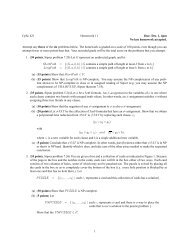
1. (6 pts) The point p <strong>ca</strong>n be specified as p A = (2, 5) T in the coordinate frame W, with orthonormal basis vectors i and j.Specify the coordinates of point p in frames A and B.2. (10 pts) Find the 3x3 homogeneous transformation which transforms a point from Frame B into the Frame W coordinatesystem. That is, give M where p W = Mp B . Verify your solution using one of your answers to question 2.3. (12 pts) True/false• The only way to specify a viewing transformation is by using eye point, lookat point, and up vector.• If a surface is transformed by a nonuniform s<strong>ca</strong>le, transforming its normal vector by the same transformation willleave it perpendicular to the surface.• The homogeneous points (1,2,3,4) and (1,2,3,8) map to the same Cartesian point after homogenization.• Using display lists will affect performance differently depending on the graphi<strong>cs</strong> <strong>ca</strong>rd in the machines.• A rotation transformation leaves the w coordinate of a homogeneous point unchanged.• The transformation from an orthographic view volume to the display coordinate system depends on the size of theviewport.• An object with normalized devices coordinates (5, 5, 5) is visible in the final framebuffer image given a viewportof width 500 and height 500.• In OpenGL, vertices are always specified in the world coordinate system.• In OpenGL, light positions <strong>ca</strong>n be specified in either the world or the viewing coordinate system.• The transformation from the RGB to the HSV colorspace <strong>ca</strong>n be expressed by a 4x4 matrix.• The CIE colorspace incorporates measurements of human perceptual response and encodes all luminance informationin one of its three channels.• Intensity in the HSI colorspace correctly encodes luminance information taking into account human perceptualresponse.2
4. (16 pts) Draw shapes 2, 3, 4, and 5 transformed by the appropriate OpenGL commands in the left column below. ThedrawShape() code is shown in the middle column, and the result of the first <strong>ca</strong>ll is shown in the right column.glIdentity();drawShape(); // shape 1glRotate(90, 0, 0, 1);glTranslate(1, 0, 0);drawShape(); // shape 2glRotate(-90, 0, 0, 1);glPushMatrix();glTranslate(1, 0, 0);drawShape(); // shape 3glS<strong>ca</strong>le(1, 2, 1);glTranslate(1, -2, 0);drawShape(); // shape 4glTranslate(-2, 2, 0);glRotate(90, 0, 0, 1);glTranslate(-1, -1, 0);glS<strong>ca</strong>le(1, .5, 1);glRotate(90, 0, 0, 1);glPopMatrix();glTranslate(-2, 1, 0);drawShape(); // shape 5drawShape() {glBegin(GL_POLYGON);glVertex(0,0,0,1);glVertex(2,0,0,1);glVertex(2,1,0,1);glVertex(1,1,0,1);glVertex(1,3,0,1);glVertex(0,3,0,1);glEnd(GL_POLYGON);}y54321x0 1 2 3 4 5a) shape 2b) shape 3y543210 1 2 3 4x5y543210 1 2 3 4x5c) shape 4d) shape 5y543210 1 2 3 4x5y543210 1 2 3 4x53
5. (8 pts) Scene Graphs. The transformation matrices in the following scene graph define the relative transformations ofeach body part with respect to its parent. foo.• (4 pts) Your <strong>ca</strong>t wants an earring, be<strong>ca</strong>use all the other kitties have one. You should draw it as an offset withrespect to the coordinate system of the ear. Give the expression for the composite transformation that shouldbe in the modelview matrix to get from viewing to ear coordinates: that is, the transformation to get from theviewing coordinate system to the ear coordinate system, or equivalently the matrix that takes a point specified inear coordinates and transforms it to viewing coordinates.• (4 pts) You want to add a TailCam, a second <strong>ca</strong>mera that lets you see what things would look like from a point ofview of the end of your <strong>ca</strong>t’s tail. (You will get dizzy when your <strong>ca</strong>t sees a mouse and lashes its tail!) Give theexpression for the composite transformation that you should use for B, the viewing matrix for the TailCam. (B isthe V2W matrix from the coordinate frame point of view, and the W2V matrix from the point/object point of view.)6. (4 pts) A point p is at lo<strong>ca</strong>tion (50,50) in DCS (display coordinates), with a viewport of width 100 and height 100. Giveits x and y lo<strong>ca</strong>tion in NDCS (normalized device coordinates).4
7. (20 pts) Viewing.1 glMatrixMode(GL_PERSPECTIVE);2 glLoadIdentity();3 glFrustum(-5, 5, -5, 5, 15, 150);4 glMatrixMode(GL_MODELVIEW);5 glLoadIdentity();6 gluLookAt(0, 0, 10, 0, 0, 0, 0, 1, 0);7 drawIguana();The drawIguana() function draws an iguana in the current coordinate system with extent ranging from -5 to 5 in x,-2 to 2 in y, and 0 to 1 in z. When you run your program, you are sad that you <strong>ca</strong>nnot see the iguana.• (4 pts) Fix this problem so that the iguana is visible and nearly fills the image plane, by changing only the eye point.State which line you are changing, and give new parameters for the OpenGL command.• (4 pts) Fix this problem so that the iguana is visible and nearly fills the image plane, by changing only the nearclipping plane. State which line you are changing, and give new parameters for the OpenGL command.• (4 pts) Change the view by rotating the image of the iguana 90 degrees clockwise on the image plane, by changingonly the up vector. State which line you are changing, and give new parameters for the OpenGL command.• (4 pts) Give the viewing matrix produced by the original code above. That is, the V2W matrix considered from thecoordinate frame point of view, or the W2V matrix considered from the transforming object point of view.• (4 pts) Give the perspective matrix produced by the original code above. That is, the N2V matrix considered fromthe coordinate frame point of view, or the V2N matrix considered from the transforming object point of view.5
8. (24 pts) For each equation below, sketch the new lo<strong>ca</strong>tion L’ of the L shape on the grid and provide the OpenGL sequenceneeded to <strong>ca</strong>rry out those operations. Use the function drawL(), which draws an L shape with the lower left corner atthe current origin as shown below. You may assume the matrix mode is GL MODELVIEW and that the stack has been initializedwith glLoadIdentity(). For reference, the OpenGL command syntax is glRotatef(angle,x,y,z),glTranslatef(x,y,z), glS<strong>ca</strong>lef(x,y,z).y54321x0 1 2 3 4 5drawL();A =⎡⎢⎣1 0 0 00 1 0 10 0 1 00 0 0 1⎤ ⎡⎥⎦ , B = ⎢⎣0 1 0 0−1 0 0 10 0 1 00 0 0 1⎤ ⎡⎥⎦ , C = ⎢⎣1 0 0 10 1 0 00 0 1 00 0 0 1⎤ ⎡⎥⎦ , D = ⎢⎣2 0 0 00 1 0 00 0 1 00 0 0 1⎤⎥⎦a) L’ = CBD Ld) L’ = ABAB Ly543210 1 2 3 4x5y543210 1 2 3 4x5b) L’ = CABC Le) L’ = BBBB Ly543210 1 2 3 4x5y543210 1 2 3 4x5c) L’ = BDC Lf) L’ = CCAA Ly543210 1 2 3 4x5y543210 1 2 3 4x56