
You also want an ePaper? Increase the reach of your titles
YUMPU automatically turns print PDFs into web optimized ePapers that Google loves.
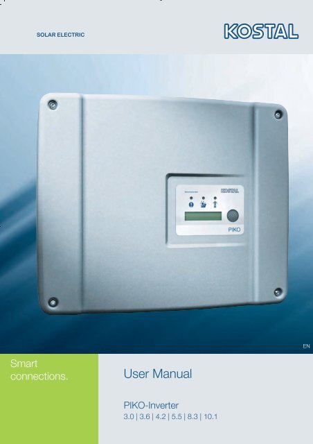
Installation and Operating <strong>Manual</strong>ENSmartconnections.User <strong>Manual</strong>PIKO-Inverter3.0 | 3.6 | 4.2 | 5.5 | 8.3 | 10.1
LEGAL NOTICEKOSTAL Solar Electric GmbHHanferstrasse 679108 Freiburg i. Br.GermanyTel. +4976147744-100Fax +49 761 477 44 - 111www.kostal-<strong>solar</strong>-electric.comExclusion of liabilityAll names of usage, trade names, product names or other designations given in thismanual may also be legally protected even without special labelling (e.g. as atrademark). KOSTAL accepts no liability and gives no assurance that they can befreely used.The illustrations and texts have been compiled with great care. However, thepossibility of errors cannot be ruled out. The compilation is made without anyguarantee.Software version above FW: 3.75 UI: 3.71General note on non-sexist languageKOSTAL is aware of the importance of language with regard to the equality ofwomen and men and always makes an effort to reflect this in the documentation.Nevertheless, for the sake of readability we are unable to use non-gender-specificterms throughout and have used the masculine form as a rule.© 2010 KOSTAL Industries Electric GmbHAll rights reserved by KOSTAL, including those of reproduction by photocopy andstorage in electronic media. Commercial use or distribution of the texts, displayedmodels, diagrams and photographs appearing in this product is not permitted. Themanual may not be reproduced, stored, transmitted or translated in any form or bymeans of any medium – in whole or in part – without prior written permission.
ContentsContents1 Notes on this manual . . . . . . . . . . . . . . . . . . . . . . . . . . . . . . . . . . . . . . . . . . . . . . . . . . . . . . . . . . 52 Proper use . . . . . . . . . . . . . . . . . . . . . . . . . . . . . . . . . . . . . . . . . . . . . . . . . . . . . . . . . . . . . . . . . . 53 Safety instructions. . . . . . . . . . . . . . . . . . . . . . . . . . . . . . . . . . . . . . . . . . . . . . . . . . . . . . . . . . . . . 64 Unit and system description . . . . . . . . . . . . . . . . . . . . . . . . . . . . . . . . . . . . . . . . . . . . . . . . . . . . . 75 Installation . . . . . . . . . . . . . . . . . . . . . . . . . . . . . . . . . . . . . . . . . . . . . . . . . . . . . . . . . . . . . . . . . . 105.1 Installation . . . . . . . . . . . . . . . . . . . . . . . . . . . . . . . . . . . . . . . . . . . . . . . . . . . . . . . . . . . . . 105.2 Electrical connection . . . . . . . . . . . . . . . . . . . . . . . . . . . . . . . . . . . . . . . . . . . . . . . . . . . . . . 125.3 Connecting the AC side . . . . . . . . . . . . . . . . . . . . . . . . . . . . . . . . . . . . . . . . . . . . . . . . . . . 125.4 Connecting the DC side . . . . . . . . . . . . . . . . . . . . . . . . . . . . . . . . . . . . . . . . . . . . . . . . . . . 135.5 Setting the country of use . . . . . . . . . . . . . . . . . . . . . . . . . . . . . . . . . . . . . . . . . . . . . . . . . . 165.6 Connecting communication components with communication board I . . . . . . . . . . . . . . . . 175.7 Connecting communication components with communication board II . . . . . . . . . . . . . . . . 245.8 Installing accessories with communication board I . . . . . . . . . . . . . . . . . . . . . . . . . . . . . . . 305.9 Installing accessories with communication board II . . . . . . . . . . . . . . . . . . . . . . . . . . . . . . . 345.10 Closing the housing . . . . . . . . . . . . . . . . . . . . . . . . . . . . . . . . . . . . . . . . . . . . . . . . . . . . . . 366 Commissioning and de-commissioning . . . . . . . . . . . . . . . . . . . . . . . . . . . . . . . . . . . . . . . . . . . 376.1 Switching on the inverter . . . . . . . . . . . . . . . . . . . . . . . . . . . . . . . . . . . . . . . . . . . . . . . . . . 376.2 Setting up communication and accessories . . . . . . . . . . . . . . . . . . . . . . . . . . . . . . . . . . . . 376.3 Handover to the operator . . . . . . . . . . . . . . . . . . . . . . . . . . . . . . . . . . . . . . . . . . . . . . . . . . 436.4 Switching the inverter off/decommissioning . . . . . . . . . . . . . . . . . . . . . . . . . . . . . . . . . . . . 436.5 Servicing/maintenance . . . . . . . . . . . . . . . . . . . . . . . . . . . . . . . . . . . . . . . . . . . . . . . . . . . . 446.6 Disassembly and disposal . . . . . . . . . . . . . . . . . . . . . . . . . . . . . . . . . . . . . . . . . . . . . . . . . 457 Inverter operating characteristics . . . . . . . . . . . . . . . . . . . . . . . . . . . . . . . . . . . . . . . . . . . . . . . 467.1 Display field . . . . . . . . . . . . . . . . . . . . . . . . . . . . . . . . . . . . . . . . . . . . . . . . . . . . . . . . . . . . 467.2 Determine the operating status (operating LEDs) . . . . . . . . . . . . . . . . . . . . . . . . . . . . . . . . 467.3 Determining the operating status (display) . . . . . . . . . . . . . . . . . . . . . . . . . . . . . . . . . . . . . . 467.4 Displaying operating values and changing settings (communication board I) . . . . . . . . . . . . 477.5 Displaying operating values and changing settings (communication board II) . . . . . . . . . . . 487.6 Faults . . . . . . . . . . . . . . . . . . . . . . . . . . . . . . . . . . . . . . . . . . . . . . . . . . . . . . . . . . . . . . . . . 488 System monitoring . . . . . . . . . . . . . . . . . . . . . . . . . . . . . . . . . . . . . . . . . . . . . . . . . . . . . . . . . . . 508.1 Displays and settings via web server . . . . . . . . . . . . . . . . . . . . . . . . . . . . . . . . . . . . . . . . . . 508.2 Logging into the web server . . . . . . . . . . . . . . . . . . . . . . . . . . . . . . . . . . . . . . . . . . . . . . . . 508.3 Downloading log data . . . . . . . . . . . . . . . . . . . . . . . . . . . . . . . . . . . . . . . . . . . . . . . . . . . . . 518.4 Displaying log data . . . . . . . . . . . . . . . . . . . . . . . . . . . . . . . . . . . . . . . . . . . . . . . . . . . . . . . 518.5 End data transfer to a <strong>solar</strong> portal . . . . . . . . . . . . . . . . . . . . . . . . . . . . . . . . . . . . . . . . . . . . 529 Appendix . . . . . . . . . . . . . . . . . . . . . . . . . . . . . . . . . . . . . . . . . . . . . . . . . . . . . . . . . . . . . . . . . . . 539.1 Technical data . . . . . . . . . . . . . . . . . . . . . . . . . . . . . . . . . . . . . . . . . . . . . . . . . . . . . . . . . . 539.2 Block diagram . . . . . . . . . . . . . . . . . . . . . . . . . . . . . . . . . . . . . . . . . . . . . . . . . . . . . . . . . . 559.3 Type plate . . . . . . . . . . . . . . . . . . . . . . . . . . . . . . . . . . . . . . . . . . . . . . . . . . . . . . . . . . . . . 569.4 Warranty and service information . . . . . . . . . . . . . . . . . . . . . . . . . . . . . . . . . . . . . . . . . . . . 56Index . . . . . . . . . . . . . . . . . . . . . . . . . . . . . . . . . . . . . . . . . . . . . . . . . . . . . . . . . . . . . . . . . . . . . . . . . . . 57Installation and Operating <strong>Manual</strong> for PIKO Solar Inverter 3
1 Notes on this manualThank you for choosing a <strong>solar</strong> inverter PIKO fromKOSTAL Solar Electric GmbH!We hope you enjoy consistently high energy yields withthe PIKO inverter and your photovoltaic system.If you have any technical questions, please call ourservice hotline: +49 761 477 44 - 2221 Notes on this manualRead this manual carefully in its entirety. It containsimportant information on the installation and operationof the inverter. Pay particular attention to theinstructions regarding safe usage. KOSTAL assumesno liability for damages arising from the nonobservanceof this manual.This manual is an integral part of the product. It onlyapplies to <strong>solar</strong> inverters PIKO from KOSTAL SolarElectric GmbH. Retain this manual and pass it onto thenew owner in the event of a new operating company.The installer as well as the user must always haveaccess to this manual and must be familiar with itscontents, particularly the safety instructions.Target groupsThis manual, especially chapters 5 (‹Installation›) and 6(‹Commissioning and de-commissioning›), are intendedfor specialist tradespersons. Information relevant forthe operator can be found in chapters 7 (‹Inverteroperating characteristics›) and 8 (‹System monitoring›).The inverters described in this manual differ from oneanother in terms of particular technical details.Information and instructions, which only apply tocertain device types are indicated accordingly, forexample "PIKO 4.2/5.5".Information concerning your safety or that of the unit ishighlighted especially.DANGERNon-observance of safety warnings, which areidentified by the signal word DANGER, can cause fatalinjuries.WARNINGNon-observance of safety warnings, which areidentified by the signal word WARNING, can causeserious and/or permanent injuries.ATTENTIONNon-observance of safety warnings, which areidentified by the signal word ATTENTION, can causedamage to property.2 Proper useThe PIKO inverter converts DC current into symmetric,single-phase (PIKO 3.0/3.6) or 3-phase (PIKO4.2/5.5/8.3/10.1) AC current and feeds this into thepublic mains grid. The unit may only be used in gridconnectedphotovoltaic systems within the permissiblepower range and under the permissible environmentalconditions. The unit is not intended for mobile use.Inappropriate use can be hazardous and lead to injuryor even death of the user or third parties. Materialdamage to the unit and other equipment can alsooccur. The inverter may therefore only be used for itsintended purpose.Exclusion of liabilityAny use that differs from or goes beyond the statedintended purpose is considered inappropriate. Themanufacturer accepts no liability for any damageresulting from this. Modifications to the inverter areprohibited. The inverter may only be used if safe tooperate and in technically perfect condition. Anyinstance of misuse will cause the termination of thewarranty, guarantee and general liability of themanufacturer.Only a qualified electrician may open the unit. Theinverter must be installed by an electrician who isresponsible for observing the applicable norms andregulations. Work that could affect the electrical powersystem of the respective utility company at the site ofthe <strong>solar</strong> energy feed-in may only be carried out byqualified electricians expressly authorised (licensed) bythe utility company.This includes changes to the factory presetparameters. The installer must always observe theregulations of the utility company. The utility company'sspecifications must always be observed when settingthe parameters, since otherwise the ENS (gridmonitoring) will no longer function correctly.CAUTIONNon-observance of safety warnings, which areidentified by the signal word CAUTION, can causeminor and/or reversible injuries.Installation and Operating <strong>Manual</strong> for PIKO Solar Inverter 5
3 Safety instructions3 Safety instructionsImproper handling during installation and whileoperating inverters can cause potentially fatal situationsdue to electrical shock.Furthermore, non-observance of this manual couldcause burns or even fires due to the potentially highsurface temperature of the cooling elements.Therefore always observe all safety instructions in thismanual.Safety markingsThe labels and markings attached to the housing by themanufacturer may not be changed or removed.Proper installationThe installer must be familiar with and observe all localinstallation regulations valid in their respective country.The installer must be familiar with this manual andfollow all instructions.Lightning protectionThe lightning protection for the inverter depends onwhether the building or photovoltaic system isequipped with an external lightning arrester.If the building has been provided with an externallightning arrester, overvoltage protection type 2 ismandatory on the AC and DC side, and must beinstalled on-site.If the building has not been provided with an externallightning arrester, we recommend the installation ofovervoltage protection type 2 on-site on the AC- andDC side.We also recommend the installation of overvoltageprotection for communication lines (RJ45, RS485,sensors...). When several inverters are connected,overvoltage protection must be installed on both endsof the cable.Electromagnetic fieldsDanger due to electromagnetic fields!People with pacemakers, metallic implants orhearing aids may experience complications.Such people should consult their doctor beforeentering a site with inverters.Opening the unitOnly a qualified electrician may open and perform workon the unit.Fatal voltages are produced in the inverterduring operation.• Switch off the unit completely (DC side and AC side)before all work.• Wait at least five minutes after switching off until thecondensers have discharged.Disconnecting cablesBurns from arcs!Cables must never be removed from the deviceduring operation as dangerous arcs may form.First de-energise the DC side, then removeplug-in connectors!Disconnecting the DC side on units with a DC-loadbreak switchThe DC load break switch is not an isolation switch forcomplete disconnection. The inverter is isolated fromthe PV generator only when the plug-in connectors aredisconnected.It is possible to plug in and to disconnect the plug-inconnectors under voltage – but not while underelectrical load.Touching the inverter during operationIndividual housing sections, especially thecooling elements, can reach temperatures ofover 80 °C during operation.• Do not touch hot components.• Allow the device to cool down before maintenancework.Avoiding risk of fireIndividual housing sections, especially thecooling elements, can reach temperatures ofover 80 °C during operation.• Comply with regulations when choosing theinstallation site.• Always keep the ventilation openings clear.• Do not obstruct the unit.• Do not store combustible and flammable materialsnear the inverter.6Installation and Operating <strong>Manual</strong> for PIKO Solar Inverter
4 Unit and system description4 Unit and system descriptionFunction1Fig. 1: Inverter PIKO2 34 5 6 7 81 Screws2 Cover3 Display4 Housing5 Plug-in connector or cable openings to connect the <strong>solar</strong>modules6 DC load break switch7 Cable openings for optional communication8 Opening for the mains cablePIKO <strong>solar</strong> inverters are powerful and transformerlessstring inverters. They convert the DC current producedby photovoltaic modules into symmetric, single-phase(PIKO 3.0/3.6) or 3-phase (PIKO 4.2/5.5/8.3/10.1) ACcurrent and feed this into the public mains grid. Powergeneration independent of the public grid ("islandoperation") is not possible.Through three-phase technology, PIKO4.2/5.5/8.3/10.1 combine the stability and durability oflarge central inverters with the high efficiency oftransformerless string inverters.The single-phase inverters PIKO 3.0/3.6 use themodern and fail-safe phase-shifting procedure tomonitor the grid.To improve efficiency, PIKO 4.2/5.5/8.3/10.1 use onlyone or two phases with a limited power input (less than10 percent of the rated power) for feeding current intothe grid. The device selects the phase on a randombasis each time.The PIKO inverters are fitted with an integrated DC loadbreak switch. No external break switch is thereforerequired. The <strong>solar</strong> modules are connected to theinverter via plug-in connectors.The PIKO inverters are available in various output sizes(see table 16, page 53) and offer you maximumflexibility in configuring your <strong>solar</strong> energy system.This is achieved through a broad DC input voltagerange, independent MPP regulators for each input,which enable the connection of <strong>solar</strong> modules invarious combinations (alignment, inclination, quantity,type). In order to conveniently display the yields andproduction data of your photovoltaic system, theinverter has an integrated web server, seechapter 6.2.1.Note: There are currently inverters available with twodifferent communication PCBs (communicationboards), clearly visible from a small display oncommunication board I and from a large display oncommunication board II.Fig. 2: Small display on inverter with communicationboard IFig. 3: Large display on inverter with communicationboard IIInstallation and Operating <strong>Manual</strong> for PIKO Solar Inverter 7
4 Unit and system description1367542Fig. 4: System illustration of a grid-connected photovoltaic system1 PV string 12 PV string 2 and 3 (optional)3 Inverter4 Electronic DC load break switchInputsThe PIKO operates using the so-called string principle:In this system, a limited number of <strong>solar</strong> modules(depending on the desired power output whileconsidering the maximum permissible input voltage)are connected in series as a string, which is thenconnected to the inverter. The number of stringsdepends on the configuration of the <strong>solar</strong> energysystem.The strings are connected to the inverter via plug-inconnectors.Depending on the unit type, one, two or threeseparately controllable inputs are available. Inputs oneand two can sometimes be connected in parallel inorder to allow a higher input current (see table 2, page14). For PIKO 5.5, parallel connection is not possible.You can obtain the highest yields through the maximumpermissible input voltage. This is achieved by using thesmallest possible number of inputs with identicalpower. An example: For the installation of 48 <strong>solar</strong>modules, it is better to use two inputs with 24 moduleseach rather than three inputs with 16 modules each.Be sure to always observe the specifications on thetype plate!5 AC mains cable6 Single-phase or 3-phase AC line circuit breaker(for layout, see table 1, page 13)7 Feed meterInternal consumptionInstead of feeding the electricity generated by the PIKOinverter into the grid, you can also use some or all of ityourself. Using a control signal that the inverter emitsvia a switch output (relay), electrical devices can beautomatically switched on via an external load relay assoon as sufficient power is available. On the inverter,you can set the minimum power that must be availablebefore the devices are switched on.This internal consumption option is ideal for deviceswhich are only needed when the sun is shining (such asair conditioning systems) or those which can wait untilbright sunshine is present (washing machines anddryers). In addition, internal consumption reduces theload on the public electricity grid.Note for systems installed in Germany: You canclaim a special internal consumption payment asdefined in EEC 2009 (section 33 para. 2) for electricitythat you can demonstrate to have used yourself. Thisapplies to systems of up to 30 kW which did not goonline before 1 January 2009.8Installation and Operating <strong>Manual</strong> for PIKO Solar Inverter
4 Unit and system descriptionControl signalExternal load relayPhotovoltaic moduleInverterProductionmeterFeedmeterConsumptionmeterJumper switchGridReactive power controlNote: The information in this section applies only tosystems in Germany.In accordance with the German Federal ElectricityAssociation BDEW's medium-voltage regulations,since April 2011 grid operators can demand the feed-inof inductive or capacitive reactive power with adisplacement factor of 0.95.The PIKO inverters are designed so that they can beused to control reactive power.The installer sets the parameters required by the localgrid operator during installation, see chapter 5.5.You can get further information on this from our servicehotline (+49 761 477 44 - 222).Fig. 5: Internal consumption (example illustration:connecting the devices and recording the internalelectricity consumption is the operator's responsibility)Active power controlConsumer devicesNote: The information in this section applies only tosystems in Germany.On the basis of the renewable energy law (EEG)introduced in Germany on the 1.1.2009, grid operatorsmay temporarily limit the output of feed-in systems withan output of 100 kW or more ("power reduction"). Thishelps protect the grid from overloading and avoid gridfailure.The ripple control receiver required for this, which isprovided by the grid operator, can be connected to thePIKO inverter. The information received in this way canbe relayed by the inverter to the other inverters in thesystem via an Ethernet- or RS485 network.Note: If your photovoltaic system has an output of lessthan 100 kW, active power control is, of course, notrequired.In addition, in accordance with the German FederalElectricity Association BDEW's regulations for theconnection and parallel operation of power-generatingunits on the medium-voltage grid dated June 2008("Medium-voltage regulations"), the PIKO inverters, candepending on frequency, limit the power fed to the grid.This form of power restriction may also be necessaryfor systems connected to the low-voltage grid if yourconnection to the public grid accesses the mediumvoltagemains.The installer makes the appropriate settings – afterconsultation with the local grid operator – duringinstallation; see chapter 5.5.Transport and storageThe function if the inverter has been tested and it hasbeen carefully packed prior to delivery. Upon delivery,check that the delivery is complete and check for anypossible transport damage. Complaints and damageclaims are to be directly addressed to the shippingcompany.ATTENTIONRisk of damage when the inverter is placed on itsunderside.• Always place the inverter on its rear side (coolingelements) after unpacking.If stored for a longer period before installation, allcomponents of the inverter must be kept dry and dustfreein the original packaging.Installation and Operating <strong>Manual</strong> for PIKO Solar Inverter 9
5 InstallationScope of deliveryThe packaging contains:— 1 inverter (1)— 1 wall mount (not for replacement devices) (2)— 1 GD containing operating instructions (3)—1 poly bag with:– 2 sealing caps (3-pole, 5-pole) for sealing the ACterminal with lead (mandatory in Italy) (4)– Installation accessories: 4 screws DIN 571 A26×45,4 dowels with 8 mm diameters and 40 mm inlength,1 tapping screw DIN 7516 form A galvanisedM4x10) (5)– 2 wire jumpers for parallel connection (notpossible on all units) (6)– Plug seals for the screw connection for thenetwork cable (7)– 2 insulating caps (8)— Poly bag each with (number of poly bagscorresponding to string inputs):– 2 counterparts for plug-in connectors (9)(1 × plug, 1 × socket)15 InstallationDANGERRisk of death due to electrical shock!When performing any work on the inverter and feedcables:• Switch off the voltage on the AC and DC sides ofthe unit.• Secure the voltage supply from beingunintentionally switched back on.• Wait at least five minutes until the condensers of theinverter have discharged.• Check the device and cables to make certain thatthey are voltage-free.• Prior to installation, check whether the local mainsgrid and the power output of the photovoltaicmodules are compatible with the technical data ofthe inverter. Observe the type plate.• Observe the specified sequence of installationtasks: Install the inverter first, then connect it to theelectricity supply.• Observe the VDE safety regulations, all nationalregulations in the country of use as well as theconnection and safety regulations of the localenergy supplier.• Pay attention to careful and correct installation: Nodirt, no foreign bodies and no moisture may enterthe inverter.9876544x 1xL1 N PEL1 L2 L3 N PEFig. 6: Scope of delivery235.1 InstallationDANGERRisk of death due to improperly performedinstallation!Improper installation can lead to life-threateningsituations. The inverter and the components connectedto it can also be damaged, increasing the risk of fire.Selecting the installation siteYou can install the inverter indoors as well as outdoors.The ideal installation site is as dry and cool as possible(such as a cellar or the non-sunny side of the building).Avoid direct sunlight since the inverter capacity isreduced at high temperatures. For outdoor installation,the inverter should be protected from direct rainfall by aprojecting roof or canopy.The inverter must be installed in a permanent location.It is not intended for mobile use.Observe the following conditions when selecting theinstallation site:– Do not install the inverter near highly flammablematerials or in areas at risk of explosion.10Installation and Operating <strong>Manual</strong> for PIKO Solar Inverter
5 Installation– The cooling fins of the inverter can reach temperaturesof over 80 °C during operation. Select an adequatelyheat-insulated base that cannot ignite at theabove mentioned temperatures. Maintain adequatesafety clearance from flammable materials in thesurroundings.– The base must be of sufficient stability to bear theweight of the inverter. Plasterboard walls andwooden planks are not suitable for the base!– The inverter is intended for vertical installation on awall. The unit can be tilted no more than 10° to theleft or right and no more than 60° backwards. Theunit may not be tilted forwards or installed in ahorizontal position.– The ambient temperature must be between -20 °Cand +60 °C.The air humidity must always be between 0 % and95 % (non-condensing).– In order to ensure adequate cooling, a clearance ofat least 200 mm must be maintained above andbelow the inverter. On the left and right sides theremust be a clearance of at least 100 mm (seeillustration 7, page 11).– Leave enough room on the side of the unit in orderto be able to disassemble the fan for maintenancework, if necessary.– If the inverter is installed in an enclosed area, (forexample in a switch cabinet or small room), use aforced ventilation system to ensure that the hot air isproperly dissipated.– The inverter should be accessible for anysubsequent work. The LEDs, the display and thetype plate should be visible and easy to read.– Install the inverter in a place where children forexample cannot pull out the cables by accident.In areas where there is risk of flooding, the unitshould be installed at an adequate height.– Bear in mind that the inverter may produce noiseduring operation, which may be consideredannoying in living quarters.Installing the wall mount and hanging theinverter• Mark the positions of the drill holes at the installationsite by using the wall mount as a drilling template.1.Fig. 7: Installing the inverter (top: PIKO 3.0/3.6/4.2/5.5,bottom: PIKO 8.3/10.1)1 Required space for cooling2 Outer dimensions of the inverter1.10042max.10°2.100max.10°2.45200151042003.1120020742003.421002245100• Drill holes and insert wall anchors if necessary.• Screw the wall mount to the intended surface.Use the supplied screws.• Hang the inverter on the wall mount.• Fasten the inverter on the underside using thesupplied screw.Installation and Operating <strong>Manual</strong> for PIKO Solar Inverter 11
L1L2 L3 N PE5 Installation5.2 Electrical connectionDANGERRisk of death due to electrical shock!If exposed, voltage-carrying cables make contact, anelectrical arc can occur, posing a life-threateninghazard.• Only remove as much of the cable insulation as isnecessary. The insulation must reach up to theterminal.DANGERRisk of death due to electrical shock!Metal slivers can fall into the inverter when removing theinsulation. Contact with voltage-carrying componentsduring operation can cause an electrical arc to occur,posing a life-threatening hazard.• Never remove the cable insulation above theinverter!Opening the housing• Release the four screws of the cover and carefullyremove the cover.5.3 Connecting the AC side• Unscrew the cable screw connection for the mainscable (1 in figure 8).Fig. 9: Pressing the blind plug out of the sealing ring1 Blind plug2 Sealing ringWe recommend a mains cable of type NYM-J 5×2.5(for single-phase connection NYM-J 3×2.5). The outerdiameter of the cable can be 9…17 mm, the crosssectionof the individual conductors can be a max. of4 mm² for flexible cables and a max. of 6 mm² for rigidcables. The three-phase feed-in to the mains meansthat the currents are lower than single-phase feed-in,allowing the cable cross-section to be smaller. Forflexible cables, we recommend using core end sleeves.• Remove the sheath and the insulation of the mainscable as much as needed.• First thread the unscrewed union nut (4 in illustration10) and then the sealing ring (3 in illustration 10)over the cable.• Guide the mains cable through the cable duct intothe interior of the inverter.• Thread the sealing cap (illustration 11) over themains cable. The sealing cap is mandatory in Italy.1212Fig. 8: Connections on the housing1 Cable screw connection for mains cable143• Press the blind plug and the sealing ring out of thescrew connection from the inside towards theoutside using a screwdriver or similar implement.Detach the sealing ring from the blind plug.Fig. 10: Laying the mains cable1 AC terminal (5-pole; for PIKO 3.0/3.6: 3-pole)2 Mains cable3 Sealing ring4 Union nut12Installation and Operating <strong>Manual</strong> for PIKO Solar Inverter
5 InstallationFig. 11: Sealing cap for AC terminalNote: To connect the AC and DC cables, the inverter isequipped with spring-loaded terminal strips (figure 12).Fig. 12: Spring-loaded terminal strip: Fastening thecable (left), detaching the cable (right)• Connect the conductors of the mains cable to theAC terminal in accordance with the labelling(figure 13).L1 L2 L3 N PE1 Sealing cap2 Sealing wire3 Mains cableL1 L2 L3 N PEFig. 13: Mains cable connected (left without sealingcap, right with sealing cap (illustration showsPIKO 8.3/10.1)• Place the sealing cap on the terminal block andattach the seal. The sealing cap is mandatory inItaly.32.1.L1 L2 L3 N PE12• Screw the union nut with inner sealing ring and plugtightly onto the cable screw connection.Note: The cable connection seals the housing againstmoisture and also relieves tension on the cable toensure it is not pulled out of the terminals by its ownweight.• Check whether all lines are securely connected andcannot become loose.• Switch off the current distributor and secure thevoltage supply from being unintentionally switchedback on. Ensure that the current distributor is deenergised.• Lay the mains cable from the inverter to the currentdistributor.• WARNING! Risk of fire due to overcurrent andheating of the mains cable. Install a line circuitbreaker into the mains cable between the inverterand the feed meter (see table 1) to secure it againstovercurrent.3.03.6• Do not switch on the voltage yet.5.4 Connecting the DC sidePIKO4.25.58.3Type Single-pole Three-poleTripping characteristic10.1Rated current 25 A 16 A 25 ATable 1: Recommended AC line circuit breakerThe number of strings to be connected depends on theconfiguration of the photovoltaic system. First connectstring 1, then strings 2 and 3 (if present).The cross-section of the DC cables should be as largeas possible, a maximum of 4 mm² for flexible cablesand 6 mm² for rigid cables.The cross-section of the DC cables must be 4–6 mm².We recommend using tin-plated cables. If non-tinplatedcables are used, the copper strands may oxidiseas a result of which the transition resistance of thecrimp connections will be too high.If the rated current of a string is higher than thepermitted input value of the inverter, you can, on certainunit types, connect the DC inputs 1 and 2 in parallel(see table 2). Two bridges have been added to the unitsfor this purpose (figure 14).BInstallation and Operating <strong>Manual</strong> for PIKO Solar Inverter 13
5 InstallationFig. 14: DC bridgesNumber of DCinputsNominal DCcurrent per inputMax. DC inputcurrent per inputIs parallelconnection ofinputs 1 & 2possible?DC nominalcurrent for parallelconnection 1 & 2Max. DC inputcurrent for parallelconnection input1& 23.03.64.2PIKO5.58.310.11 2 2 3 2 38A 8A 8A 8A 11.5A 11.5A9A 9A 9A 9A 12.5A 12.5ANo Yes Yes No Yes Yes— 12 A 12 A — 20 A 23 A— 13 A 13 A — 25 A 25 ATable 2: Connecting inputs in parallelWhen supplied, the inverter is equipped with plug-inconnectors from Multi-Contact (type MC4) or fromLumberg (type LC4).During assembly, always observe the latestspecifications from the manufacturer of the plug-inconnectors, e.g. regarding required special tools,permissible tightening torques etc.Further information is available, for example online atwww.multi-contact.com or at www.lumberg.com.Installing the plugs onto the DC cables• Ensure that the DC load break switch is set to O(OFF). The plug-in connectors may be plugged inand disconnected in this position only.• Eliminate any existing earth faults or short circuits inthe strings.• Remove 6–7.5 mm of insulation from the DC cable.Be careful not to cut any individual conductors.• Crimp the DC cables according to therecommendations of the plug-in connectors'manufacturer.• Guide the crimped contacts from behind into theplug or socket insulation until they engage.Ensure that the parts matching the plug-inconnector couplings are used on the inverter.Observe the polarity of the cables.• Pull gently on the cable in order to check whetherthe metal part has engaged.• Check that assembly has been carried out inaccordance with the recommendations of the pluginconnectors' manufacturer.• Hand-tighten the cable connections. The tighteningtorque must match the DC cable. Typical values arebetween 2.5 Nm and 3 Nm.Inserting DC cables into the inverter1 2 3Fig. 15: DC inputs (the number of inputs which can beused depends on the model)1 Plug-in connector couplings DC input 12 Plug-in connector couplings DC input 23 Plug-in connector couplings DC input 3• Check that the inverter is de-energised.• Set the DC load break switch to OFF.OFFFig. 16: DC load break switch OFF• Remove the two plug seals from the plug-inconnectors. Keep the plug seals.14Installation and Operating <strong>Manual</strong> for PIKO Solar Inverter
5 Installation• Insert the PV string plugs until they engage in thecorresponding counterparts on the inverter(figure 17).1DC1DC223Fig. 18: Inputs 1 and 2 connected in parallel(PIKO 3.6/4.2)1 DC bridges2 PV string 13 PV string 2Fig. 17: Connecting the PV string1DC1DC2• Pull on the plugs in order to ensure that they areproperly engaged.Note: To disconnect the plug-in connectors, press theengaging clips together manually or with the toolavailable from the plug-in connectors' manufacturerand pull the plug out.• To connect additional strings, repeat the aboveinstallation steps for each string.Any additional plug-in connectors needed areavailable from specialist shops.• PIKO 3.6/4.2: If you connect DC input 1 and 2 inparallel, remove the cable ends of the second DCinput from the clamping block DC2 and insulate thefree cable ends using the caps supplied.• PIKO 3.6/4.2/8.3/10.1: If required, now connectinputs 1 and 2 in parallel. Insert the bridgessupplied into the clamps as shown (figure 18/19).Note: Please note that a parallel connection is notpossible with PIKO 5.5.2Fig. 19: Inputs 1 and 2 connected in parallel (PIKO8.3/10.1)1 DC bridges2 PV string 13 PV string 2• Leave the plug seals on the plug-in connectors notin use to protect them from moisture and dirt.3Installation and Operating <strong>Manual</strong> for PIKO Solar Inverter 15
5 Installation5.5 Setting the country of usePrior to initial commissioning, the country in which theinverter is used must be specified. This is necessary sothat the grid monitoring functions appropriately for thelocal mains grid.Once the AC voltage has been initiallyswitched on, the country setting ispermanently set!If the country setting is incorrect, the inverter will notfunction.In order to set the country of use, consult the chaptercorresponding to your communication board.5.5.1 Communication board I1• Set the DIP switch as appropriate for the country ofuse according to table 3.Country Switch setting Default languageDelivery condition(inverterdeactivated)GermanyGermany MSRnoneGermanGermanIncluding frequency-dependent power restriction in accordance with themedium-voltage regulations (MSR)SpainFrancePortugalItalyGreece(continental)SpanishFrenchPortugueseItalianEnglish 1Greece (islands) English 1The NetherlandsBelgiumLuxembourgDutchFrenchFrenchFig. 20: DIP switch1 DIP switchThe country setting is made via the DIP switch (1) onthe communications board I.Note: You can change the preset language of thedisplay and integrated web server (see Table 3) to anyselection you wish after the commissioning.ATTENTIONThe communication board may be damaged byelectrostatic discharge.• Use a blunt, non-metallic utensil to activate the DIPswitch.• Touch a grounded point, for example the holder forthe housing screw connection on the bottom right,before touching the circuit board.SwitzerlandCzech RepublicAustriaUnited Kingdom,Cyprus 2HungarySloveniaBulgariaRomania,Slovakia, TurkeyTable 3: DIP switch settings1 For technical reasons, we regret that the display is unableto depict any Greek letters. We apologise for anyinconvenience caused by this limitation.2 For single-phase inverters only.FrenchCzechGermanEnglishHungarianEnglishEnglish16Installation and Operating <strong>Manual</strong> for PIKO Solar Inverter
5 Installation5.5.2 Communication board IIAfter commissioning, a prompt to select the countrysetting appears in the display (4).4Fig. 21: Display on the inverter• Press the arrow keys (1 or 2) to select the desiredcountry.• Press the Enter key (3) to go to the confirmationwindow.• Press the arrow keys (1 or 2) to switch between"NO" and "YES".• Press the Enter key (3) to confirm your selection.5.6 Connecting communicationcomponents with communicationboard INow install the available communication components,such as an analogue modem, cable etc. The GSMmodem is an exception, since the PIN code of the SIMcard must be entered before the GSM modem can beinstalled in the inverter with the SIM card (seesection 6.2.2).DANGERRisk of death due to electrical shock!Single-insulated cables from communicationcomponents may come into contact with parts carryingmains voltage if the insulation is damaged.• Only connect double-insulated cables to theinverter.123Overview of the communications optionsIn terms of communication options, four differentsituations are taken into account.1. Inverter configuration.2. Direct retrieval of the current yield value and/orsaved log data.3. Transferring the yield data to an Internet <strong>solar</strong> portal.4. Remote retrieval of the current yield value and/orsaved log data.Situation 1: Configuring the inverterAll communication settings – for example, activation ofdata transfer to a <strong>solar</strong> portal – are made via theintegrated web server. To access the configuration onthe web server, you will need a computer, which mustbe connected to the inverter.The inverter is equipped with an Ethernet interface(RJ45 socket) for this purpose. The computer mustalso be equipped with this type of interface. Theoperating system is irrelevant. An Internet browsermust be installed on the computer.You can then connect the inverter and computer eithera) via a local network (switch and Ethernet cable, seefigure 22), orb) directly via a so-called crossover cable(see figure 23).Version a) is the best option when a local network isalready available. Several inverters can also beconnected in the network (figure 24).Version b) is the best option when no switch isavailable.Note: Ethernet cables ("network cables") are standardconnection cables commonly used for computernetworks. These cables are suitable for mostapplications and are available from computer shops.A crossover cable is a special type of Ethernet cable,on which the plugs are configured differently. Thisallows two units to be directly connected to each otherwithout the need for a switch or hub.You will only need a crossover cable if the inverter isconnected directly to a computer, meaning without aswitch/hub (figure 23).ATTENTIONThe communication board may be damaged byelectrostatic discharge.• Touch a grounded point, for example the holder forthe housing screw connection on the bottom right,before touching the circuit board.Installation and Operating <strong>Manual</strong> for PIKO Solar Inverter 17
5 InstallationAlternatively, you can connect the inverters to eachother via the RS485 interface and then only need toconnect one of the inverters via Ethernet (figure 25).With this type of connection, the web server of theinverter connected via the Ethernet also displays thecurrent output data of the other inverters. However, theweb server and the stored log data are only availablefor the inverter connected via Ethernet.123 4Fig. 22: Connecting inverter and computer withEthernet cables and switch1 Inverter2 Ethernet cable3 Switch/hub4 Computer (for configuration or data retrieval)12345Fig. 23: Connecting inverter and computer withcrossover cable1 Inverter2 Crossover cable3 Computer (for configuration or data retrieval)121324 5Fig. 24: Multiple inverters in the network1 Inverter2 Additional inverters3 Ethernet cable4 Switch/hub5 Computer (for configuration or data retrieval)Situation 2: Direct retrieval of the yield dataThe retrieval of the current yield data as well as thestored inverter log data is also only possible using acomputer. The units are cabled as described undersituation 1.3Fig. 25: Connecting inverters via the RS485 andretrieving performance data via Ethernet1 Inverter2 Additional inverters, max. 200 depending on cable length3 RS485 connection4 Crossover cable5 ComputerSituation 3: Data transfer to a <strong>solar</strong> portalThe inverter can send yield data to an Internet <strong>solar</strong>portal at regular intervals.To do so,a) the inverter must be connected to a DSL router orto a network with Internet access orb) the inverter must have an integrated analoguemodem or wireless modem (GSM, available as anaccessory).Version a) requires a DSL connection. If your inverteris located close to where you already have a DSLconnection, you can use the available connectionfor transmission.Note: If the inverters are connected to the Internet byDSL router in the local network, both direct retrieval ofthe log data as well as transmission of the log data of allconnected inverters is possible through a <strong>solar</strong> portal.Version b) with an analogue modem requires theinverter to be connected to a separate analoguetelephone connection or an analogue extension of atelecommunications system. This requires a telephoneconnection close by. The inverter must be connectedto the telephone connection at all times.For version b) with a wireless modem, you will requirea SIM data card from a mobile phone provider. Theremust also be adequate wireless reception at the pointof installation.18Installation and Operating <strong>Manual</strong> for PIKO Solar Inverter
5 InstallationMake sure that the access point name is set correctly.To do this, use the "GSM-Link" configuration tool (seesection Installing GSM modem).A detailed description can be found on our website andthe CD provided.Note: Inadequate reception quality – for example inareas with a low network coverage – can lead toconnection problems and to the GSM modem diallinginto the net too often. Depending on the price model ofthe GSM contract, this can result in increased costs.The reception quality is also affected by the weather.We recommend testing the reception with a normalmobile telephone for a few days prior to installation toensure that adequate reception is possible despitediffering weather conditions.Ensure that the antenna cable length does not exceed8 m!Note: For installations with several inverters, you willonly need one modem.Version b) with one or two invertersIf you have two inverters, you can connect them bothwith a crossover cable and equip one of the two with amodem. There is then no need for a switch or hub. Theadditional connection to a computer or a DSL router isnot an option in this case.Version b) with two or more invertersTo transfer data from several inverters to a <strong>solar</strong> portalvia modem, first connect the inverter to a switch/hubvia an Ethernet cable. You will only need one modem:the inverter with the modem then assumes the functionof a router for the other inverters.The number of network connectable inverters is inprinciple only limited by the available IP addresses. Inpractice, for data transfers via GSM or analoguemodem, a max. of 30 inverters can be networked, fordata transfers via DSL, a max. of 300 inverters can benetworked.16234 5WWWFig. 27: Connecting several inverters through theEthernet and transferring data via modem1 2 3 4WWWFig. 26: Connecting two inverters with a crossovercable, transferring data via modem1 Inverter (without modem)2 Inverter with an integrated modem (analogue or GSM)3 Crossover cable4 Telephone connection box or mobile communicationsantenna (depending on the modem being used)1 Inverter with an integrated modem (analogue or GSM)2 Additional inverters (without a modem), max. 293 Ethernet cable4 Switch/hub5 Computer (for configuration and, if applicable, directretrieval)6 Telephone connection box or mobile communicationsantenna (depending on the modem being used)Situation 4: Remote retrieval of yield dataYou can also connect to the inverter remotely instead ofthrough a local network. This may possibly involveadditional connection costs.Similar to situation 3, the inverter must eithera) be connected to a DSL router orb) have a modem (analogue or GSM) installed.Installation and Operating <strong>Manual</strong> for PIKO Solar Inverter 19
5 InstallationVersion a) Inverter with DSL connection to theInternetTo ensure the inverter can actually be accessed via theInternet, several requirements must be met.— The inverter must have a fixed IP address in thelocal network.— Port forwarding must be configured to the inverterIP address in the router.— The router must be assigned a fixed IP address bythe Internet provider or you must register the routerwith a DynDNS service to connect the dynamicrouter IP address with a fixed name.The inverter can then be accessed over the Internetunder the domain name provided by the DynDNSservice, and you can connect to the inverter withany Internet browser (see figure 28).Setting up a port forwarding and a DynDNS service cannot be illustrated in detail here due to the vast numberof different devices and services available.Note: DynDNS services are also referred to as"Dynamic DNS" and "DNS host service provider".For the router to remain accessible at all times underthe selected domain name, the router communicateseach change of IP address to the DynDNS service.Many of the available routers offer such a function,however, a router usually only supports certainDynDNS services.With certain router manufacturers, the port forwardingfunction is called "virtual server" or a similar term.For further information, see the operating manual ofthe router.135Version b) with an integrated modemAn inverter connected to the telephone network by ananalogue modem can only be contacted by acomputer when the computer establishes theconnection via an analogue telephone connection orvia the analogue connection of a telecommunicationssystem (dial-in connection, see figure 29).1 2Fig. 29: Retrieving log data: Inverter connected to atelephone network1 Inverter with integrated analogue modem2 Telephone socket3 Telephone network4 Computer with modemDialling in with a computer and analogue telephoneconnection does not function reliably for an inverterwith GSM modem. We therefore recommend dialling invia a computer with a GSM modem or a mobiletelephone with a modem function (see figure 30).1 23243WWW2Fig. 28: Retrieving log data: Inverter connected to theInternet via DSL1 Inverter2 DSL router3 Internet4 Computer5 Internet-compatible mobile phone with browser function4Fig. 30: Retrieving log data: Inverter connected to amobile communications network1 Inverter with integrated GSM modem2 Mobile communications antenna3 Mobile telephone (GSM) with modem function4 Computer420Installation and Operating <strong>Manual</strong> for PIKO Solar Inverter
5 InstallationOverview of the communications interfaces4Fig. 31: Communication interfaces1 Modem (accessory)2 RJ11 socket3 RJ45 socket4 Terminal for RJ45 and RJ11321terminal adapter. To use the RJ11 interface, you willrequire a modem, available as an accessory.• Insert the plug of the telephone cable into thecorresponding socket (2 figure 31).Connecting an Ethernet cable and/ortelephone line to the cable terminalInstead of the RJ45 and RJ11 sockets, you can use thesix-pole screw terminal to connect the Ethernet cableand telephone cable (4 in figure 31). This type ofconnection is intended for installation in large systems.• Connect the lines to the cable terminal according tothe terminal assignment (table 4).12Connecting Ethernet cableYou can connect the inverter to a computer or acomputer network (Ethernet 10BaseT, 10 MBit/s) viathe RJ45 socket. Use crossover cables of category 5(Cat 5e, FTP) with a maximum length of 100 m.• Insert the plug of the Ethernet cable into thecorresponding socket (3 figure 31).Installing analogue modemA prerequisite for use of an analogue modem is ananalogue telephone connection. Using a modeminvolves additional costs. Details can be obtained fromtelecommunications providers.• Carefully attach modem to circuit board. Theuppermost plug pin on the left must be inserted intothe uppermost hole in the multipoint connector.baModemFig. 33: Cable terminalRx -Rx+1 Analogue telephone connection2 Ethernet connectionTx -Tx+Terminal Designation Description1 Tx+ Transmission pair +2 Tx– Transmission pair –3 Rx+ Reception pair +4 Rx– Reception pair –5 Modem a Telephone line a6 Modem b Telephone line bTable 4: Cable terminal connection assignment fortwisted pair cables and telephone lineInstalling GSM modemIn order to use the GSM modem, you will need a SIMdata card with a contract with a mobile phone provider.The GSM-Link software leaves you free to select yourmobile phone provider. Using a modem involvesadditional costs. Details can be obtained fromtelecommunications providers.Fig. 32: Installing the modem• Connect the telephone cable (see the followingsection).Connecting the telephone cableThe RJ11 socket is used to connect the inverter to ananalogue telephone jack or to an ISDN line with aNot every mobile phone contract issuitable for use with an inverter servicerequest.Before purchasing the SIM data card,discuss the following points with yourmobile phone provider and obtain all theaccess data you require (APN, user nameand password).Installation and Operating <strong>Manual</strong> for PIKO Solar Inverter 21
5 Installation— You should select a provider whose networksupplies the strongest GSM signal at your chosenlocation.— The tariff must allow for packet data communicationvia GPRS.— Prepaid cards which are topped up by mobile callsare not suitable.— Tariffs which specify particular times for datadownloads cannot be used.— The tariff must permit a data volume of at least 5MBper month and inverter.— It must be possible for the data settings (APN etc.)to be configured by hand.— The SIM card must be activated before installation.• Download the "GSM-Link" software from ourwebsite www.kostal-<strong>solar</strong>-electric.com from the"Service => Download" area or use the CDsupplied.• Switch the inverter off for at least 5 minutes.Fatal voltages are produced in the inverterduring operation. Only a qualified electrician mayopen and perform work on the unit.•Open the cover.• Connect an Ethernet cable to the communicationboard (RJ45 interface (network connection)) andconnect to the PC. If connecting directly (inverterwith PC – without switch), you must use a crossovercable.• Switch the inverter back on again.• Enter the serial number, inverter name or IP addressin the Internet browser's address line to go to theinverter's web server (e.g. s081230001 ors90342IE100001 or 192.168.1.1).• Enter the PIN number on the "Settings" page in the"GSM PIN" field.Fig. 34: Settings page• Launch the "GSM-Link" software.Fig. 35: GSM-Link• Enter the serial number or IP address of the inverterin the "Host/IP address" field (note: enter the letter Sand the inverter's serial number, for examplehttp://S12345FD323456.)22Installation and Operating <strong>Manual</strong> for PIKO Solar Inverter
5 Installation• In the GSM area, enter the data (APN, user nameand password) of the SIM card in the correspondingfields and confirm by selecting "Write new settings".• Switch the inverter off for at least 5 minutes.• Slide the SIM card into the card holder on theunderside of the modem.• Carefully attach GSM modem to circuit board. Theuppermost plug pin on the left must be inserted intothe uppermost hole in the multipoint connector.Fig. 37: Modem status• If the "Modem status: GSM signal strength" field isdisplaying at least two bars, the connection is OK.Fig. 36: Installing the modem• Insert the plug of the radio antenna into the GSMmodem.• Install the radio antenna where it will have the bestpossible reception.Note: The reception quality will be displayed on theweb server info page after starting up (see section‹Checking sensors and modem› in chapter 6.2).• Switch the inverter on again and wait at least2minutes.• Enter the serial number, inverter name or IP addressin the Internet browser's address line to go to theinverter's web server.• Check the current modem status on the "Info page"Activating data transfer to a <strong>solar</strong> portalThe factory default setting does not include a <strong>solar</strong>portal. To use a <strong>solar</strong> portal, you will need a portalcode. You can get further information on this from ourservice hotline (+49 761 477 44 - 222).Only the name of one <strong>solar</strong> portal will be displayed. It isnot possible to use several portals at the same time.• Open the web server's "Settings" page (seeillustration 34).• Enter the code for the intended <strong>solar</strong> portal in the"Portal-Code" field.• Click on "adopt" to save the settings.➜ The name of the <strong>solar</strong> portal will appear on thepage. The box ( ) next to the portal name wasactivated automatically.➜The portal code for Piko-control is P3421.The portal code for safer‘Sun(www.meteocontrol.com) is P202L.Data transfer is now activated.Note: To end the data transfer, see chapter 8.5 (page52).• Check that the connection is OK.• Enter the words "go online" in the "Portal code"field.• Confirm by clicking on "adopt".• Open the "Info page".Installation and Operating <strong>Manual</strong> for PIKO Solar Inverter 23
5 InstallationIf a value in minutes is stated in the "last connection toportal" field, there is a connection to the <strong>solar</strong> portal.You can then register on the <strong>solar</strong> portal and use theinverter to create a system and/or add the inverter tothis system.Note: An inverter first has to log onto the portal ("goonline") before it can be assigned to a system in theportal.5.7 Connecting communicationcomponents with communicationboard IINow install the available communication components,such as an analogue modem, cable etc. The GSMmodem is an exception, since the PIN code of the SIMcard must be entered before the GSM modem can beinstalled in the inverter with the SIM card (seesection 6.2.2).DANGERRisk of death due to electrical shock!Single-insulated cables from communicationcomponents may come into contact with parts carryingmains voltage if the insulation is damaged.• Only connect double-insulated cables to theinverter.ATTENTIONThe communication board may be damaged byelectrostatic discharge.• Touch a grounded point, for example the holder forthe housing screw connection on the bottom right,before touching the circuit board.The inverter is equipped with two Ethernet interfaces(RJ45 sockets) for this purpose. The computer mustalso be equipped with this type of interface. Theoperating system is irrelevant. An Internet browsermust be installed on the computer.You can then connect the inverter and computer eithera) directly via an Ethernet cable (see illustration 39) orb) via a local network (switch and Ethernet cable, seefigure 40).Version a) is the best option when no switch isavailable.Version b) is the best option when a local network isalready available. Several inverters can also beconnected in the network (figure 38).123Fig. 38: Multiple inverters in the network1 Inverter2 Additional inverters3 Ethernet cable4 Computer (for configuration or data retrieval)4Overview of the communications interfacesIn terms of communication options, four differentsituations are taken into account.1. Inverter configuration.2. Direct retrieval of the current yield value and/orsaved log data.3. Transferring the yield data to an Internet <strong>solar</strong> portal.4. Remote retrieval of the current yield value and/orsaved log data.12Fig. 39: Connecting inverter and computer withEthernet cable1 Inverter2 Ethernet cable3 Computer (for configuration or data retrieval)3Situation 1: Configuring the inverterAll communication settings – for example, activation ofdata transfer to a <strong>solar</strong> portal – are made via theintegrated web server. To access the configuration onthe web server, you will need a computer, which mustbe connected to the inverter.24Installation and Operating <strong>Manual</strong> for PIKO Solar Inverter
5 Installation1Fig. 40: Connecting inverter and computer withEthernet cables and switch1 Inverter2 Ethernet cable3 Switch/hub4 Computer (for configuration or data retrieval)Situation 2: Direct retrieval of the yield dataThe retrieval of the current yield data as well as thestored inverter log data is also only possible using acomputer. The units are cabled as described undersituation 1.Alternatively, you can connect the inverters to eachother via the RS485 interface and then only need toconnect one of the inverters via Ethernet (figure 41).With this type of connection, the web server of theinverter connected via the Ethernet also displays thecurrent output data of the other inverters. However, theweb server and the stored log data are only availablefor the inverter connected via Ethernet.123243 4Fig. 41: Connecting inverters via the RS485 andretrieving performance data via Ethernet1 Inverter2 Additional inverters, max. 200 depending on cable length3 RS485 connection4 Ethernet cable5 Computer5To do so,a) the inverter must be connected to a DSL router orto a network with Internet access orb) the inverter must have an integrated analoguemodem or wireless modem (GSM, available as anaccessory).Version a) requires a DSL connection. If your inverter islocated close to where you already have a DSLconnection, you can use the available connection fortransmission.Note: If the inverters are connected to the Internet byDSL router in the local network, both direct retrieval ofthe log data as well as transmission of the log data of allconnected inverters is possible through a <strong>solar</strong> portal.Version b) with an analogue modem requires theinverter to be connected to a separate analoguetelephone connection or an analogue extension of atelecommunications system. This requires a telephoneconnection close by. The inverter must be connectedto the telephone connection at all times.For version b) with a wireless modem, you will require aSIM data card from a mobile phone provider. Theremust also be adequate wireless reception at the pointof installation.Make sure that the access point name is set correctly.To do this, use the "GSM-Link" configuration tool,"Settings" page (see section Installing GSM modem).You will find a detailed description on our website.Note: Inadequate reception quality – for example inareas with a low network coverage – can lead toconnection problems and to the GSM modem diallinginto the net too often. Depending on the price model ofthe GSM contract, this can result in increased costs.The reception quality is also affected by the weather.We recommend testing the reception with a normalmobile telephone for a few days prior to installation toensure that adequate reception is possible despitediffering weather conditions.Note that the antenna position depends on themaximum cable length of the GSM antenna of 8 m!Note: For installations with several inverters, you willonly need one modem.Situation 3: Data transfer to a <strong>solar</strong> portalThe inverter can send yield data to an Internet <strong>solar</strong>portal at regular intervals.Installation and Operating <strong>Manual</strong> for PIKO Solar Inverter 25
5 InstallationVersion b)To transfer the data of several inverters to a <strong>solar</strong> portalwith a modem, connect the inverter via the Ethernet.You will only need one modem: the inverter with themodem then assumes the function of a router for theother inverters.The number of network connectable inverters is inprinciple only limited by the available IP addresses. Inpractice, for data transfers via GSM or analoguemodem, a max. of 30 inverters can be networked, fordata transfers via DSL, a max. of 300 inverters can benetworked.1523WWWFig. 42: Connecting several inverters through theEthernet and transferring data via modem1 Inverter with an integrated modem (analogue or GSM)2 Additional inverters (without a modem), max. 293 Ethernet cable4 Computer (for configuration and, if applicable, directretrieval)5 Telephone connection box or mobile communicationsantenna (depending on the modem being used)Situation 4: Remote retrieval of yield dataYou can also connect to the inverter remotely instead ofthrough a local network. This may possibly involveadditional connection costs.Similar to situation 3, the inverter must eithera) be connected to a DSL router orb) have a modem (analogue or GSM) installed.4Version a) Inverter with DSL connection to theInternetTo ensure the inverter can actually be accessed via theInternet, several requirements must be met.— The inverter must have a fixed IP address in thelocal network.— Port forwarding must be configured to the inverterIP address in the router.— The router must be assigned a fixed IP address bythe Internet provider or you must register the routerwith a DynDNS service to connect the dynamicrouter IP address with a fixed name.The inverter can then be accessed over the Internetunder the domain name provided by the DynDNSservice, and you can connect to the inverter withany Internet browser (see figure 43).Setting up a port forwarding and a DynDNS service cannot be illustrated in detail here due to the vast numberof different devices and services available.Note: DynDNS services are also referred to as"Dynamic DNS" and "DNS host service provider".For the router to remain accessible at all times underthe selected domain name, the router communicateseach change of IP address to the DynDNS service.Many of the available routers offer such a function,however, a router usually only supports certainDynDNS services.With certain router manufacturers, the port forwardingfunction is called "virtual server" or a similar term.For further information, see the operating manual of therouter.213WWWFig. 43: Retrieving log data: Inverter connected to theInternet via DSL1 Inverter2 DSL router3 Internet4 Computer5 Internet-compatible mobile phone with browser function4526Installation and Operating <strong>Manual</strong> for PIKO Solar Inverter
5 InstallationVersion b) with an integrated modemAn inverter connected to the telephone network by ananalogue modem can only be contacted by acomputer when the computer establishes theconnection via an analogue telephone connection orvia the analogue connection of a telecommunicationssystem (dial-in connection, see figure 44).Overview of the communications interfaces110081382PC / ABSXX1 2343265Fig. 44: Retrieving log data: Inverter connected to atelephone network1 Inverter with integrated analogue modem2 Telephone socket3 Telephone network4 Computer with modemDialling in with a computer and analogue telephoneconnection does not function reliably for an inverterwith GSM modem. We therefore recommend dialling invia a computer with a GSM modem or a mobiletelephone with a modem function (see figure 45).1 2243Fig. 46: Communication interfacesCommunication board II1 Modem (accessory)2 RJ11 socket3 Terminal for RS485 interface4 S0 voltage output5 RJ45 sockets6 S0 alarm outputConnecting Ethernet cableYou can connect the inverter to a computer or acomputer network (Ethernet 10/100 MBit/s) via theRJ45 socket.• Insert the plug of the Ethernet cable into one of thecorresponding sockets (5 figure 46).Installing analogue modemA prerequisite for use of an analogue modem is ananalogue telephone connection. Using a modeminvolves additional costs. Details can be obtained fromtelecommunications providers.• Carefully attach modem to circuit board. Theuppermost plug pin on the left must be inserted intothe uppermost hole in the multipoint connector.Fig. 45: Retrieving log data: Inverter connected to amobile communications network1 Inverter with integrated GSM modem2 Mobile communications antenna3 Mobile telephone (GSM) with modem function4 Computer4Fig. 47: Installing the modem• Connect the telephone cable (see the followingsection).Installation and Operating <strong>Manual</strong> for PIKO Solar Inverter 27
5 InstallationConnecting the telephone cableThe RJ11 socket is used to connect the inverter to ananalogue telephone jack or to an ISDN line with aterminal adapter. To use the RJ11 interface, you willrequire a modem, available as an accessory.• Insert the plug of the telephone cable into thecorresponding socket (2 figure 46).• Enter the PIN number on the "Settings" page in the"GSM PIN" field.Installing GSM modemIn order to use the GSM modem, you will need a SIMdata card with a contract with a mobile phone provider.The GSM-Link software leaves you free to select yourmobile phone provider. Using a modem involvesadditional costs. Details can be obtained fromtelecommunications providers.Not every mobile phone contract issuitable for use with an inverter servicerequest.Before purchasing the SIM data card,discuss the following points with yourmobile phone provider and obtain all theaccess data you require (APN, user nameand password).— You should select a provider whose networksupplies the strongest GSM signal at your chosenlocation.— The tariff must allow for packet data communicationvia GPRS.— Prepaid cards which are charged by mobile callsare not suitable.— Tariffs which specify particular times for datadownloads cannot be used.— The tariff must permit a data volume of at least 5MBper month and inverter.— It must be possible for the data settings (APN etc.)to be configured by hand.— The SIM card must be activated before installation.• Switch the inverter off for at least 5 minutes.Fatal voltages are produced in the inverterduring operation. Only a qualified electrician mayopen and perform work on the unit.•Open the cover.• Connect an Ethernet cable to the communicationboard (RJ45 interface (network connection)) andconnect to the PC.• Switch the inverter back on again.• In the Internet browser, enter the serial number,inverter name or IP address in the address line to goto the inverter's web server (e.g. s081230001 ors90342IE100001 or 192.168.1.1).Fig. 48: Settings page• Launch the "GSM-Link" software.Fig. 49: GSM-Link28Installation and Operating <strong>Manual</strong> for PIKO Solar Inverter
5 Installation• Enter the serial number or IP address of the inverterin the "Host/IP address" field (note: enter the letter Sand the inverter's serial number, for examplehttp://S12345FD323456.)• In the GSM area, enter the data (APN, user nameand password) of the SIM card in the correspondingfields and confirm by selecting "Write new settings".• Switch the inverter off for at least 5 minutes.• Slide the SIM card into the card holder on theunderside of the modem.• Carefully attach GSM modem to circuit board. Theuppermost plug pin must be inserted into theuppermost hole in the multipoint connector.• Check the current modem status on the "Info page"Fig. 51: Modem status• If the "Modem status: GSM signal strength" field isdisplaying at least two bars, the connection is OK.Fig. 50: Installing the modem• Insert the plug of the radio antenna into the GSMmodem.• Install the radio antenna where it will have the bestpossible reception.Note: The reception quality will be displayed on theweb server info page after starting up (see section‹Checking sensors and modem› in chapter 6.2).• Switch the inverter on again and wait at least2minutes.• In the Internet browser, enter the serial number,inverter name or IP address in the address line to goto the inverter's web server.Activating data transfer to a <strong>solar</strong> portalThe factory default setting does not include a <strong>solar</strong>portal. To use a <strong>solar</strong> portal, you will need a portalcode. You can get further information on this from ourservice hotline (+49 761 477 44 - 222).Only the name of one <strong>solar</strong> portal will be displayed. It isnot possible to use several portals at the same time.• Open the web server's "Settings" page (seeillustration 48).• Enter the code for the intended <strong>solar</strong> portal in the"Portal-Code" field.The portal code for Piko-control is P3421.The portal code for safer‘Sun(www.meteocontrol.com) is P202L.• Click on "adopt" to save the settings.The name of the <strong>solar</strong> portal will appear on thepage. The box ( ) next to the portal name wasactivated automatically.Data transfer is now activated.Installation and Operating <strong>Manual</strong> for PIKO Solar Inverter 29
5 InstallationNote: To end the data transfer, see chapter 8.5(page 52).• Check that the connection is OK.• Enter the words "go online" in the "Portal-Code"field.• Confirm by clicking on "adopt".• Open the "Info page".If a value in minutes is stated in the "last connection toportal" field, there is a connection to the <strong>solar</strong> portal.You can then register on the <strong>solar</strong> portal and use theinverter to create a system and/or add the inverter tothis system.Note: An inverter first has to log onto the portal("go online") before it can be assigned to a system inthe portal.5.8 Installing accessories withcommunication board IIf available, now install accessories such as sensors orripple control receiver.DANGERRisk of death due to electrical shock!The communication board is energised!Single-insulated cables from communicationcomponents may come into contact with parts carryingmains voltage if the insulation is damaged.• Only connect double-insulated cables in theinverter.ATTENTIONThe communication board may be damaged byelectrostatic discharge.• Touch a grounded point, for example the holder forthe housing screw connection on the bottom right,before touching the circuit board.Overview of the accessory interfacesFig. 52: Communication board I connections1 Switch output (S0/Al OUT)2 RS485 interface3 DIP switch for RS485 configuration4 Terminal for analogue interfacesConnecting the switch outputThe switch output (terminal S0/AL-OUT, position 1 infig. 52) has different functions depending on how it isset (see ‹Setting the switch output function› on page39). It can be used as an S0 interface, as an alarmoutput or for switching on devices (for internalconsumption).S0 interface: The switch output functions as a pulseoutput as described in DIN EN 62053-31 with aconstant rate of 2000 pulses per kilowatt hour. Using asuitable receiver device such as an energy meter or adisplay, you can record and display the energy yield ofyour photovoltaic system.Alarm output: The switch output functions as apotential-free NC contact. It opens when a malfunctionoccurs (see ‹Faults› on page 48).Internal consumption: The switch output functions asa potential-free NO contact. It closes when the setconditions are fulfilled (see section ‹Setting theconditions for switching on devices (internalconsumption)› on page 39).For more information, refer also to the text and image insection ‹Internal consumption›, on page 8.4321Max. loadMax. voltageConnections100 mA250 V (AC or DC)Neutral polarityTable 5: Switch output technical dataNote: You must install a component such as anexternal load relay between the inverter and theconsumer device. Do not connect any consumerdevices directly to the switch output.• Connect all wires to the appropriate terminals(fig. 52, position 1).Connecting the S0 input (energy pulse meter)The S0 input allows you to record the pulses of anenergy meter or a second inverter.30Installation and Operating <strong>Manual</strong> for PIKO Solar Inverter
5 InstallationNote: While the second inverter will not be displayed inthe <strong>solar</strong> portal, its energy yield is included in the firstinverter's data (in total).When using the S0 input, the analogue inputs Aln3 andAln4 are inactive. The web server of the inverter showsthe pulses counted on the info page.• Connect the lines to the terminal (4 in figure 52)according to the terminal assignment (table 6).1<strong>AG</strong>NDS0-InFig. 53: Example of the connection of an externalenergy meter at the S0 In input1 S0 In input2 External energy meterConnecting analogue sensorsThe inverter features four analogue inputs to which youcan connect, for example, temperature and irradiationsensors or wind sensors. The additional measured dataenable a more precise monitoring of the photovoltaicsystem.The sensors must have an output voltage of 0...10 V(factory setting). An additional voltage supply may berequired, depending on the sensor.Note: When using the S0 input, the analogue inputsAln3 and Aln4 are inactive.Note: If the inverter is intended for connecting a ripplecontrol receiver, you cannot connect sensors.• Connect the lines to the terminal according to theterminal assignment (figure 54 and table 6).2Terminal Designation Description1 RS485 A RS485 A2 RS485 B RS485 B3 GND Ground for RS4854 S0 In S0 input (energy pulse meter)5 AIn1 Inputs for analogue sensors6 AIn2(0...10 V) or for ripple controlreceivers7 AIn38 AIn49 <strong>AG</strong>ND Ground for analogue inputsand S0 input10 +5V 5 V output for external sensors(not potential-free; max.10 mA) or for ripple controlreceiversTable 6: Cable terminal connection assignmentConnecting a ripple control receiver for activepower controlNote: The information in this section applies only tosystems in Germany.The inputs for analogue sensors can be used toconnect a ripple control receiver for active powercontrol (in accordance with the Renewable EnergyLaw, as applicable in Germany). This function must beactivated via the inverter web server (see section‹Setting the analogue input functions› in chapter 6.2.2).The inverter must then be linked via Ethernet (figure 55)or RS485 (figure 56) so that the inverter connected tothe ripple control receiver can forward the informationreceived to the other inverters.12 3 4+5V<strong>AG</strong>NDAIn4AIn3AIn2AIn1S0-InGNDBARS485Fig. 54: Cable terminal1 Voltage output2 Analogue inputs3 S0 input (energy pulse meter)4 RS485Installation and Operating <strong>Manual</strong> for PIKO Solar Inverter 31
5 Installation+5V<strong>AG</strong>NDAIn4AIn3AIn2AIn1S0-InGNDBARS485123450%167Fig. 55: Connecting the ripple control receiver forinverters with Ethernet connections1 Master inverter2 Additional inverters3 Ethernet cable4 Switch/hub5 5-conductor connection at analogue-in6 Ripple control receiver7 Grid12345 6Fig. 56: Connecting the ripple control receiver forinverters with RS485 connections1 Master inverter2 Additional inverters3 RS485 connection (2-conductor)4 5-conductor connection at analogue-in5 Ripple control receiver6 GridFig. 57: Connecting the ripple control receiver to theinverter1 Ripple control receiver30%60%100%Connecting RS485Connections for the serial RS485 interface are foundon the terminal for analogue interfaces (figure 54).Using RS485 , up to 200 inverters – depending on theinverters used – can be connected, see Table 7.Additional components can be connected to RS485.An additional level converter may be required in somecases. Use a twisted-pair cable for connection, such asLiYCY 2 × 2 × 0.25.To do so, the DIP switch for the RS485 configuration(1 in figure 58) must be set accordingly on thecommunication boards of all inverters.1• Connect the ripple control receiver lines inaccordance with the terminal assignment (figure 57and table 6).Fig. 58: DIP switch for RS485 configuration1 DIP switch for RS485 configuration32Installation and Operating <strong>Manual</strong> for PIKO Solar Inverter
5 InstallationIt is possible to mix inverters with and without DIPswitch for the RS485 configuration. The potentialconnection scope and the DIP switch setting requiredare illustrated in Table 7.If all inverters for connection are equipped with DIPswitches, cable lengths of up to 500 m are possible.Note: If other RS485 units are connected in a RS485network in addition to the inverters (e. g. a display), thenumber of inverters which can be connected and themaximum cable lengths may be limited.ATTENTIONThe communication board may be damaged byelectrostatic discharge.• Use a blunt, non-metallic utensil to activate the DIPswitch.• Touch a grounded point, for example the holder forthe housing screw connection on the bottom right,before touching the circuit board.• If necessary, switch the termination on using DIPswitch 1 and switch the bus supply voltage on usingthe DIP switches 2 and 3.Connection scopeInverter1 2 3 nmax. 20 inverters without DIP switch without DIP switch without DIP switch without DIP switchmax. 20 inverters without DIP switch without DIP switch without DIP switchOn1234max. 20 inverters when the inverteris at a distance of nwithout DIP switchOn1234On1234On1234max. 200 invertersOn1234On1234On1234On1234Table 7: DIP switch for RS485 configurationNote: If you have the corresponding expertise, you canconnect the inverter to a serial interface (RS232 orUSB) of your computer via a signal level converter.For this type of connection, however, only the currentperformance data can be accessed. The integratedweb server and the stored log data are not available.• Connect the lines to the terminal (4 in figure 54)according to the terminal assignment (table 6).Installation and Operating <strong>Manual</strong> for PIKO Solar Inverter 33
5 Installation5.9 Installing accessories withcommunication board IIIf available, now install accessories such as sensors orripple control receiver.DANGERRisk of death due to electrical shock!Single-insulated cables from communicationcomponents may come into contact with parts carryingmains voltage if the insulation is damaged.• Only connect double-insulated cables in theinverter.ATTENTIONThe communication board may be damaged byelectrostatic discharge.• Touch a grounded point, for example the holder forthe housing screw connection on the bottom right,before touching the circuit board.Overview of the accessory interfaces10081382PC / ABSXX23Internal consumption: The switch output functions asa potential-free NO contact. It closes when the setconditions are fulfilled (see section ‹Setting theconditions for switching on devices (internalconsumption)› on page 39).For more information, refer also to the text and image insection ‹Internal consumption›, on page 8.Max. loadMax. voltageConnections100 mA250 V (AC or DC)Neutral polarityTable 8: Switch output technical dataNote: You must install a component such as anexternal load relay between the inverter and theconsumer device. Do not connect any consumerdevices directly to the switch output.• Connect all wires to the appropriate terminals(fig. 59, position 1).Connecting the S0 input (energy pulse meter)The S0 input allows you to record the pulses of anenergy meter or a second inverter.Note: While the second inverter will not be displayed inthe <strong>solar</strong> portal, its energy yield is included in the firstinverter's data (in total).When using the S0 input, the analogue inputs Aln3 andAln4 are inactive. The web server of the inverter showsthe pulses counted on the info page.• Connect the lines to the terminal (4 in figure 59)according to the terminal assignment (table 9).1Fig. 59: Communication board II connections1 Switch output (S0/Al OUT)2 Terminal for analogue interfaces3 RS485 interfaceConnecting the switch outputThe switch output (terminal S0/AL-OUT, position 1 infig. 59) has different functions depending on how it isset (see section ‹Setting the switch output function› onpage 39). It can be used as an S0 interface, as an alarmoutput or for switching on devices (for internalconsumption).S0 interface: The switch output functions as a pulseoutput as described in DIN EN 62053-31 with aconstant rate of 2000 pulses per kilowatt hour. Using asuitable receiver device such as an energy meter or adisplay, you can record and display the energy yield ofyour photovoltaic system.Alarm output: The switch output functions as apotential-free NC contact. It opens when a malfunctionoccurs (see ‹Faults› on page 48).1<strong>AG</strong>NDFig. 60: Example of the connection of an externalenergy meter at the S0 In input1 S0 In input2 External energy meterS0-In234Installation and Operating <strong>Manual</strong> for PIKO Solar Inverter
5 InstallationConnecting analogue sensorsThe inverter features four analogue inputs to which youcan connect, for example, temperature and irradiationsensors or wind sensors. The additional measured dataenable a more precise monitoring of the photovoltaicsystem.The sensors must have an output voltage of 0...10 V.An additional voltage supply may be required,depending on the sensor.Note: When using the S0 input, the analogue inputsAln3 and Aln4 are inactive.Note: If the inverter is intended for connecting a ripplecontrol receiver, you cannot connect sensors.• Connect the lines to the terminal according to theterminal assignment (figure 61 and table 9).1+12V<strong>AG</strong>NDFig. 61: Cable terminal1 Voltage output2 Analogue inputs3 S0 input (energy pulse meter)4 RS485Terminal Designation Description1 RS485 A RS485 A2 RS485 B RS485 B3 GND Ground for RS4854 S0 In S0 input (energy pulse meter)5 AIn1 Inputs for analogue sensors6 AIn2(0...10 V) or for ripple controlreceivers7 AIn38 AIn4AIn42 3 4AIn3AIn2AIn1S0-InGNDBARS4859 <strong>AG</strong>ND Ground for analogue inputsand S0 input10 +12V 12 V output for externalsensors (not potential-free;max. 100 mA) or for ripplecontrol receiversTable 9: Cable terminal connection assignmentConnecting a ripple control receiver for activepower controlNote: The information in this section applies only tosystems in Germany.The inputs for analogue sensors can be used toconnect a ripple control receiver for active powercontrol (in accordance with the Renewable EnergyLaw, as applicable in Germany). This function must beactivated via the inverter web server (see section‹Setting the analogue input functions› in chapter 6.2.2).The inverter must then be linked via Ethernet or RS485(figure 62) so that the inverter connected to the ripplecontrol receiver can forward the information received tothe other inverters.12345 6Fig. 62: Connecting the ripple control receiver forinverters with Ethernet or RS485 connections1 Master inverter2 Additional inverters3 Ethernet cable, alternatively RS485 connection(2-conductor)4 5-conductor connection at analogue-in5 Ripple control receiver6 Grid• Connect the ripple control receiver lines inaccordance with the terminal assignment (figure 63and table 9).Installation and Operating <strong>Manual</strong> for PIKO Solar Inverter 35
5 Installation+12V<strong>AG</strong>NDAIn4AIn3AIn2AIn1S0-InGNDBARS485Note: If you have the necessary expertise, you canconnect the inverter to a serial interface (RS232 orUSB) of your computer via a signal level converter.For this type of connection, however, only the currentperformance data can be accessed. The integratedweb server and the stored log data are not available.• Connect the lines to the terminal (4 in figure 61)according to the terminal assignment (table 6).0%30%60%100%15.10 Closing the housing• Using cable ties, fasten all cables to the recesses inthe protective plate.Ensure that all cables run directly over theprotective plate and do not protrude over the side ofthe protective plate.Fig. 63: Connecting the ripple control receiver to theinverter1 Ripple control receiverConnecting RS485Connections for the serial RS485 interface are foundon the terminal for analogue interfaces (figure 61).Using RS485 , up to 200 inverters – depending on theinverters used – can be connected.Additional components can be connected to RS485.An additional level converter may be required in somecases. Use a twisted-pair cable for connection, such asLiYCY 2×2×0.25.To do this, you must set the bus prestress and bustermination menu items in the user menu to ON(fig. 84).If using an inverter with communication board II, allother inverters must also be fitted with communicationboard II. Cable lengths of up to 500 m are possible.Note: If other RS485 units are connected in a RS485network in addition to the inverters (e. g. a display), thenumber of inverters which can be connected and themaximum cable lengths may be limited.• For the connection, activate the bus prestress in theuser menu of the first inverter and the bustermination in the user menu of the first and lastinverters.Fig. 64: Fastening cable to protective plate• Screw all union nuts together with sealing ringtightly onto the cable screw connection.Recommended tightening torques: 1.5 Nm (M12)and 8 Nm (M25).• Check whether all lines are securely connected andcannot become loose.• Remove any foreign objects from the inverter (tools,wire cuttings, etc.).• Fit the cover and bolt it tight.36Installation and Operating <strong>Manual</strong> for PIKO Solar Inverter
6 Commissioning and de-commissioning6 Commissioning and de-commissioning6.1 Switching on the inverterFor the initial commissioning, sufficient <strong>solar</strong> irradiationmust exist so that a DC input voltage of at least 180 Vis available for the inverter.• Turn the DC load break switch to ON or switch onthe DC strings one after another via the external DCisolator.Fig. 65: DC load break switch ON• Switch on the grid voltage via the line circuitbreaker.If the following message appears on the display, thecountry of use is not set.If using communication board I, switch off the devicevoltage on the AC and DC sides and set the country ofuse as described in chapter 5.5.The inverter is now in operation: the display lights upand successively shows the device type, the countrysetting, the hardware and software versions and thename of the inverter.The yellow LED lights up and the device automaticallycarries out the required tests according toDIN VDE 0126. If the yellow LED does not light up, theinput voltage may be too low.When the tests have been successfully completed, thegreen LED lights up and the inverter begins feeding incurrent to the grid.ONFig. 66: Display message if the country of use is notset (communication board I)select countryGermanyFig. 67: Display message if the country of use is notset (communication board II)If the green LED does not light up, the input voltage orthe power may be too low or a fault has occurred (seethe chapter "Fault correction").Note: With a limited power input, PIKO4.2/5.5/8.3/10.1 use only one or two phases forfeeding current into the grid. The device selects thephase on a random basis each time.Setting the language• If desired, set the display to a different language(see chapter 7.4).6.2 Setting up communication andaccessoriesPerform the remaining setup using the web server ofthe inverter.Note: You can change all settings which you make atany time and as often as you like with the exception ofthe country of use.6.2.1 Connecting to the web server ofthe inverter• Connect the inverter with a computer, as describedin chapter 5.6 or 5.7.• Set the Ethernet interface (TCP/IP protocol) of thecomputer so that the IP address automaticallyobtains the DNS server address. To alter thissetting, administrator access rights may berequired.• Start your Internet browser and enter the letter Sand the serial number of the inverter in the addressbar, for example http://S12345FD323456The log-in window for the web server opens.• Enter user name and password. The factorydefaults for user name and password are set asfollows:User name: pvserverPassword: pvwr• Confirm the inputs by clicking on "OK".The main screen of the inverter is displayed.Installation and Operating <strong>Manual</strong> for PIKO Solar Inverter 37
6 Commissioning and de-commissioning6.2.2 Configuring settings• Click on the "Settings" link.The "Settings" page is displayed.Fig. 68: Main page of the web server (the number ofinputs- and outputs displayed may vary depending onunit type).Fig. 69: Settings pageSettingS-no.Item numberLanguageNameRS485 inverterbus addressData acquisitionSwitch outputfunctionInternalconsumptionFunction ofanalogue inputsDescriptionInverter serial numberTable 10: Web server settingsItem number of the inverterSelection of the language for the web displayAllocation of a name to the inverterUnit address for the RS485 interfaceChoose between a saving interval of 15 or60 minutesThis defines whether the switch output isused as an S0 interface, alarm output or forswitching devices (for internal consumption).Settings for controlling internal consumption.These settings only take effect when theswitch output function is set to "internalconsumption".Configuration of the analogue inputs forconnecting sensors or for active powercontrol38Installation and Operating <strong>Manual</strong> for PIKO Solar Inverter
6 Commissioning and de-commissioningSettingNetworkPublic lineGSM PINNew login-passwordPortal codeData exportDescriptionChanging the languageConfiguration of the inverter network interface(Ethernet)Only required when using an analoguemodem (optional accessory) and an analoguetelephone systemPIN for the GSM modem SIM card. For furtherinformation on configuration and installation ofthe GSM modem, see chapter 5.7.Change of passwordEntry field for the portal code for changing the<strong>solar</strong> portal displayed upon 'data export'Activation of data transfer to the <strong>solar</strong> portaldisplayed ( ) or deactivation ( )Table 10: Web server settings (cont.)You can select a different language for the web serverfrom the drop-down list.• Select the intended language.• Click on "accept" to save the settings.Changing the nameYou can assign a name of your own choosing to theinverter. When connecting the browser to the webserver you can then use the name instead of the serialnumber. Access with the serial number remainspossible.• Type in the name you have chosen. The letters a–z,A–Z and numbers 0–9 are all permitted. Diacritics,spaces or special characters are not permitted.• Click on "accept" to save the settings.Note: Make a note of the new name for the inverter.The name is also shown in the display of the inverter inthe submenu "settings".Configuring the RS485 addressIf you have linked two or more inverters via RS485, youmust set the RS485 addresses of the inverter so thateach address is unique.• Enter the desired address in the field "Inverter bus(RS485) address".• Click on "accept" to save the settings.Changing the saving intervalWhen selecting the saving interval, you have the optionof a 15-minute or 60-minute period between the savingprocedures. The internal memory can store the data forapproximately 100 days if the 15-minute period isselected and for about 400 days with the 60-minuteperiod.The inverter data are only saved in the unit for a limitedtime. When the internal memory is full, the oldest datawill be overwritten.To save the data on a long-term basis, you can eithertransfer the data to a <strong>solar</strong> portal or download them toa computer.• Select the desired saving interval.• Click on "accept" to save the settings.Setting the switch output function• Select whether the switch output is to be used asan S0 interface, alarm output or for switchingdevices (internal consumption).• If the output is to be used for controlling internalconsumption, you must make some additionalsettings (see the following section ‹Setting theconditions for switching on devices (internalconsumption)›).• Click on "accept" to save the settings.Setting the conditions for switching ondevices (internal consumption)To ensure that the device is only switched on when theinverter produces sufficient electricity, you can specifycertain conditions.Power limit: This is the minimum power (in watts) thatthe inverter must be producing before the device isswitched on. You can enter any value from 1 watt to999000 watts.Stable positive deviation from the limit: This is theperiod (in minutes) during which the inverter mustproduce at least the power set in the “power limit” fieldbefore the device is switched on. You can enter anyvalue from 1 minute to 720 minutes (= 12 hours).Run time: The connected device is switched on for thisperiod (in minutes) when both the above conditionshave been met. You can enter any value from 1 minuteto 1440 minutes (= 24 hours).The run time is interrupted if the inverter is switched off.As soon as sufficient power is available again, the runtime is resumed.Installation and Operating <strong>Manual</strong> for PIKO Solar Inverter 39
6 Commissioning and de-commissioningThe run time is ended and not continued again if theinverter has not produced any current for three hours.This normally happens after sunset.• You can enter you own values in the “power limit”,“stable positive deviation from the limit” and“runtime” fields or use the defaults.• Click on "accept" to save the settings.Setting the analogue input functions• Select whether the analogue inputs should be usedfor connecting sensors or a ripple control receiverfor active power control.• Click on "accept" to save the settings.Configuring the networkSample images are provided for both communicationboards I and II.As the standard default setting, the option "Auto IP /DHCP" is activated. This means that the inverterobtains its IP address automatically from a DHCPserver, such as from a DSL router for example. (ADHCP server is a program which assigns a networkaddress to its subscribers). If no DHCP server isavailable, the inverter assigns an IP address to itself.• The option "Auto IP/DHCP" is suitable for mostapplications (figure 70 or 71).1 2 354www6 71 2 354www6 7Fig. 71: Communication board II:Network settings with automatic network configurationfor an external DSL router ( Auto IP/DHCP, externalrouter)1 Inverter 1 – Auto-IP / DHCP2 Inverter 2 – Auto-IP / DHCP3 Inverter 3 – Auto-IP / DHCP4 Ethernet cable5 DSL router – with DHCP server6 Switch/hub7 Computer with network setting "Obtain IP addressautomatically"Network with a fixed IP addressesSample images are provided for both communicationboards I and II.A fixed IP address assignment ("manual networkconfiguration" setting) is only required in a few cases:— You have a local network (Ethernet) with fixed IPaddresses and wish to integrate the inverter into thenetwork (figure 72 or 73).— Or you operate the inverter through a DSLconnection with router and wish to connect to theinverter remotely via the router (figure 74 or 75).Fig. 70: Communication board I:Network settings with automatic network configurationfor an external DSL router ( Auto IP/DHCP, externalrouter)1 Inverter 1 – Auto-IP / DHCP2 Inverter 2 – Auto-IP / DHCP3 Inverter 3 – Auto-IP / DHCP4 Ethernet cable5 DSL router – with DHCP server6 Switch/hub7 Computer with network setting "Obtain IP addressautomatically"40Installation and Operating <strong>Manual</strong> for PIKO Solar Inverter
6 Commissioning and de-commissioning1 2 312344 56WWW5www6 7Fig. 72: Communication board I:Network settings with Auto IP( Auto-IP / DHCP, external router)1 Inverter with an integrated modem (analogue or GSM) –Auto IP/DHCP2 Optional additional inverters (without modem) –Auto-IP / DHCP3 Ethernet cable4 Switch/hub5 Computer with network setting "Obtain IP addressautomatically"6 Telephone connection or mobile communicationsantennaFig. 74: Communication board I:Network settings with manual network configuration forexternal DSL router, subnet mask: 255.255.255.0,external router1 Inverter 1 – IP address 192.168.1.22 Inverter 2 – IP address 192.168.1.33 Inverter 3 – IP address 192.168.1.4 and so on4 Ethernet cable5 DSL router – IP address 192.168.1.16 Switch/hub7 Computer – IP address 192.168.1.2501 2 312345WWWFig. 73: Communication board II:Network settings with Auto IP( Auto-IP / DHCP, external router)1 Inverter with an integrated modem (analogue or GSM) –Auto IP/DHCP2 Optional additional inverters (without modem) –Auto-IP / DHCP3 Ethernet cable4 Computer with network setting "Obtain IP addressautomatically"5 Telephone connection or mobile communicationsantenna45www6 7Fig. 75: Communication board II:Network settings with manual network configuration forexternal DSL router, subnet mask: 255.255.255.0,external router1 Inverter 1 – IP address 192.168.1.22 Inverter 2 – IP address 192.168.1.33 Inverter 3 – IP address 192.168.1.4 and so on4 Ethernet cable5 DSL router – IP address 192.168.1.16 Switch/hub7 Computer – IP address 192.168.1.250Installation and Operating <strong>Manual</strong> for PIKO Solar Inverter 41
6 Commissioning and de-commissioningNote: The factory default setting of the DNS serveraddress is 145.253.2.203, and it provides thealternative name resolution in the Internet. Do notchange this setting, as the export of log data to a <strong>solar</strong>portal may otherwise not function anymore.• Activate the setting "manual network configuration"if you wish to assign a fixed IP address. Enter the IPaddress and subnet mask.Note: The changed settings take effect immediatelyupon clicking on "adopt". Your inputs may have theconsequence that the inverter is no longer accessiblethrough the current connection.• Click on "accept" to save the settings.• If the inverter is to use an external router to senddata to a <strong>solar</strong> portal, activate the option "externalrouter" and enter the IP-address of the router.• Click on "accept" to save the settings.Entering the public line number (for analoguemodems only)• If applicable, enter the public line number.• Click on "accept" to save the settings.Entering the PIN code (for GSM modems only)You must enter the PIN code that you received fromyour mobile phone provider in the configuration of theinverter before you install the GSM modem with theSIM card.• Enter the PIN code of the GSM card.• Click on "accept" to save the settings.Note: If you subsequently change your mobile phoneprovider, first enter the new GSM PIN in the web serverof the inverter and then replace the SIM card in theGSM modem.Changing the passwordYou can change the preset log-in password on theintegrated web server.• Type in the intended password. The letters a–z, A–Zand numbers 0–9 are all permitted. Diacritics,spaces or special characters are not permitted.• Type the password into the "repeat" field again.• Click on "accept" to save the settings.Note: Your old password becomes invalid immediatelyafter the password change. You should therefore notethe password as a precaution.Forgotten the password? Our customer service is onhand to assist.Note: The user name cannot be changed.6.2.3 Checking sensors and modem• On the main page of the web server, click on the link"info page".The "info page" window then opens.Fig. 76: Info pageEntryx- analogueinputDescriptionShows the voltage which is currently availableon the analogue input xModem status Shows the modem status:– When the analogue modem is connectedcorrectly, "analogue modem detected" isdisplayed.– When the GSM modem is connectedcorrectly, the GSM signal strength isdisplayed.– When the modem is connected incorrectly ornot available, "modem not available" isdisplayed.Last portalconnectionNo. of energypulsesTable 11: Info pageDisplays how many minutes ago the inverter lasttransferred data to the <strong>solar</strong> portal (when thefunction is active)Displays the number of energy pulses per timeunit occurring at the S0 interface42Installation and Operating <strong>Manual</strong> for PIKO Solar Inverter
6 Commissioning and de-commissioning• Check whether the modem has been detected(analogue modem) or whether adequate receptionquality – at least two bars – is displayed (GSMmodem).Fig. 77: Modem status• If the reception quality is too low, try placing theGSM antenna in another location.Note that the reception quality also depends on theweather conditions.Note: Reception quality which is inadequate can leadto connection problems and to the GSM modemdialling into the net too often. Depending on the pricemodel of the GSM contract, this can result in increasedcosts.• Click on "back to home page" to display the homepage again.6.2.4 Activating data transfer to a <strong>solar</strong>portalThe factory default setting does not include a <strong>solar</strong>portal. To use a <strong>solar</strong> portal, you will need a portalcode. You can get further information on this from ourservice hotline (+49 761 477 44 - 222).Only the name of one <strong>solar</strong> portal will be displayed. It isnot possible to use several portals at the same time.• Open the web server's "Settings" page (seeillustration 48).• Enter the code for the intended <strong>solar</strong> portal in the"Portal-Code" field.The portal code for Piko-control is P3421.The portal code for safer‘Sun(www.meteocontrol.com) is P202L.• Click on "adopt" to save the settings.The name of the <strong>solar</strong> portal will appear on thepage. The box ( ) next to the portal name wasactivated automatically.Data transfer is now activated.6.2.5 Disconnecting• Close the browser window to disconnect from theweb server of the inverter.6.3 Handover to the operatorAfter successful installation and commissioning, givethe inverter and this manual to the user. Advise theoperator about the following points:• The position and function of the DC load breakswitch or the external DC isolator and the AC linecircuit breaker.• Safety when handling the device.• Appropriate procedure when checking andservicing the unit.• Meaning of the LEDs and the display messages.• Contact person in the event of a fault.6.4 Switching the inverteroff/decommissioningFor maintenance work and repairs, the inverter must beswitched off. It is not necessary to switch the converteroff during normal operation.• Turn the DC load break switch to OFF (figure 78) orswitch off the <strong>solar</strong> generator via the external DCisolator.No more DC input current is fed to the inverterand it ends the feed-in operation.OFFFig. 78: DC load break switch OFFIn the event that you wish to perform work on theinverter or cables, you must completely de-energisethe inverter:• Disconnect the plug-in connectors by pushing theengaging clips together and pulling out the plug.Installation and Operating <strong>Manual</strong> for PIKO Solar Inverter 43
6 Commissioning and de-commissioningNote: The plug-in connectors are designed for only alimited number of application (see the manufacturer'sspecifications). For this reason, avoid plugging them inand unplugging them unnecessarily.• Use the line circuit breaker to disconnect theinverter from the mains.• Secure the voltage supply from being switchedback on.• Allow the unit to cool down. Wait five minutes untilthe condensers of the inverter have discharged.• Ensure that all connections are de-energised.12346.5 Servicing/maintenanceDANGERRisk of death due to improperly performed work!Work performed improperly can cause life-threateningsituations. Only qualified electricians or appropriatelytrained persons may perform work on the inverter.Fig. 79: Removing the fan (PIKO 3.0/3.6/4.2/5.5)1 Fan cable2 Fan3 Fan grille4 ScrewsOnce correctly installed, the inverter operates nearlymaintenance-free.• Check the cable connections and plugs at leastonce a year.If there are loose connections, damaged cables,etc., switch off the inverter immediately.Damage may only be repaired by qualified electricians.Fan cleaningFor cooling during operation, inverters are equippedwith one or two fans. To ensure that the fans functionproperly, you should regularly perform a test of thefans. If the fans are dirty, the inverter may not beadequately cooled and the efficiency of the unitdecreases.12Fig. 80: Removing the fan (PIKO 8.3/10.1)31 Fan cable2 Fan plate with fan and grille3 ScrewsThe fan test can only be performed during feed-inmode (green LED lit). For information on starting the fantest, refer to chapter 7.4.If the fan does not run properly, it should be cleaned. Todo so, you must switch off the inverter:DANGERRisk of death due to electrical shock!There are deadly voltages in the inverter duringoperation.• Switch off the unit completely (DC side and AC side)before all work.• Wait at least five minutes after switching off until thecondensers have discharged.44Installation and Operating <strong>Manual</strong> for PIKO Solar Inverter
6 Commissioning and de-commissioning• Switch off the inverter as described in chapter 6.4.You can now clean the fan:• PIKO 3.0/3.6/4.2/5.5: Loosen the screws (4 in fig.79) and carefully remove the fan grille and the fan.PIKO 8.3/10.1: Loosen the screws (3 in fig. 80) andcarefully remove the fan plate.• Disconnect the fan cable plug connection.• Clean the fan with a soft brush.• PIKO 3.0/3.6/4.2/5.5: Reinsert the fan cable, placethe fan back into the housing and screw the fan andthe fan grille back on tightly.PIKO 8.3/10.1: Reconnect the fan cable and screwthe fan plate back onto the housing.You can now switch the inverter back on:• Turn the DC load break switch to ON or switch onthe DC strings one after another via the external DCisolator.ONFig. 81: DC load break switch ON• Switch on the grid voltage via the line circuitbreaker.6.6 Disassembly and disposalTo disassemble the inverter, proceed as follows:DANGERRisk of death due to electrical shock!There are deadly voltages in the inverter duringoperation.• Switch off the unit completely (DC side and AC side)before all work.• Wait at least five minutes after switching off until thecondensers have discharged.• Switch off the inverter as described in chapter 6.4.• Open the cover of the inverter.Loosen the terminals and cable screw connectionsand remove all DC and AC-cables.• Close the cover of the inverter.Loosen the screw on the underside of the inverterand lift the inverter off the wall mount.• Disassemble the wall mount.DisposalDispose of the inverter properly and in accordance withthe applicable regulations.The box of the inverter is made of cardboard and canbe recycled as paper. Plastic parts and the packagingsack can be sorted to plastic recycling.Installation and Operating <strong>Manual</strong> for PIKO Solar Inverter 45
7 Inverter operating characteristics7 Inverter operatingcharacteristicsThe inverter will work automatically aftercommissioning, meaning that regular operation is notnecessary.As soon as the photovoltaic module generatessufficient current, the inverter begins feeding into themains.7.1 Display fieldThe inverter indicates the respective operating statusthrough three LEDs and an LC display. You can alsoquery operating values and enter settings on thedisplay.1 2 3Note: The contact sensor responds to the touch of afinger. Do not press the contact sensor forcefully.7.2 Determine the operating status(operating LEDs)The LEDs on the front of the device indicate the currentoperating status.LED"AC" LED lit in greenDescriptionThe green LED signals that the inverter isin feed-in mode if the output voltage ofthe photovoltaic module is more than180 V."DC" LED lit in yellow The yellow LED signals the active statusof the inverter control unit.It lights up as soon as the output voltageof the photovoltaic module exceeds100 V.If the output voltage falls below 100 V,the yellow LED goes out.45No LED is lit"Fault" LED lights upor flashes redOR: "DC" LEDflashes yellowOnce energy is being fed into the mainsgrid, the yellow "DC" LED goes out andthe green "AC" LED lights up.The device is operationally ready but theinput voltage is less than 100 V.OR: The device is switched off.A fault has occurred. Remedial measurescan be found in chapter 7.6.Fig. 82: Display on the inverter(Communication board I)Table 12: LED indicators in operation1 "Fault" LED (red)2 "DC" LED (yellow)3 "AC" LED (green)4 Contact sensor5 LC display7.3 Determining the operating status(display)The operating statuses are shown on the display.DisplayDescription71 2 3456OffIdleStartFeed-in (MPP)Input voltage on the DC side(photovoltaic modules) is too lowElectronics are ready for operation, DCvoltage is still too low for feed-inInternal control measurementsaccording to VDE 0126Measurement successful, MPP control(MPP = maximum power point) activeFeed-in regulatedFeed-in power has been regulated dueto excessive device temperatureTable 13: Operating statusesFig. 83: Display on the inverter(Communication board II)1 "Fault" LED (red)2 "DC" LED (yellow)3 "AC" LED (green)4 "UP" arrow key5 "DOWN" arrow key6 Enter key7 LC display46Installation and Operating <strong>Manual</strong> for PIKO Solar Inverter
7 Inverter operating characteristics7.4 Displaying operating values andchanging settings (communicationboard I)The user menu is activated through the round contactsensor on the right next to the display.• Touch the contact sensor.The display illumination switches on.The operating values are each displayedsuccessively for three seconds.• To switch between the values more quickly, touchthe contact sensor.The inverter acknowledges the switchover with abrief signal tone.The following operating values are shown in the displaysuccessively:AC power2551Wdaily energy1.23kWhThe following data can be accessed in the "settings"submenu:— Language— IP address— Inverter name— RS485 address— Software version• To switch between the values displayed, tap thecontact sensor.• To return to the main menu from the "operatingvalues" menu item, place your finger on the contactsensor for several seconds.Changing the language• Go to the "settings" submenu and select the"language" menu option.• To activate the language selection, place your fingeron the contact sensor for several seconds.• Lightly tap the contact sensor to display theavailable languages one after another.• To confirm the selected language, place your fingeron the contact sensor for several seconds.total energy16251kWhtotal oper. time126hU-DC 1 2 3 [V]600 500 0I-DC 1 2 3 [A]2,90 1,78 0,00U-AC 1 2 3 [V]230 231 229operating modesupplysettingslanguageEnglishAuto IP / DCHP189.254.47.11nameno namefan teststartRS485 inverteraddress 128version00801.16 1.10Activate fan test• Go to the "settings" submenu and select the "startfan test" menu option.• To start the fan test, place your finger on the contactsensor for several seconds.Note: The fan test is only possible during feed-in to themains grid. If grid feeding is not actively occurring, themessage "not possible, no DC power" appears.• Note the running sounds of the fan. If the fan is notrunning or running sluggishly, it may need to becleaned or repaired. For further information, seechapter 6.5.operating dataFig. 84: User menu and "settings" submenu• Place your finger on the contact sensor for severalseconds... to freeze the current display or... to activate the submenu from the menu item"settings".Installation and Operating <strong>Manual</strong> for PIKO Solar Inverter 47
oper. timetotal126h1 2 3 [V]U-DC500 06001 2 3 [V]U-AC231 229230modeoperatingsupplyIP / DCHPAuto189.254.47.11namename notest fanstartinverterRS485128addressprestressBusAusRS485version1.1000801.167 Inverter operating characteristics7.5 Displaying operating values andchanging settings (communicationboard II)The user menu is activated by pressing any key to theright of the display.• Tap e.g. the Enter key.The display illumination switches on.The operating values are each displayedsuccessively for three seconds.• Tap the arrow keys to switch between the valuesfaster and in any direction.The inverter acknowledges the switchover with abrief signal tone.The following operating values are shown in the displaysuccessively:AC power2551Wenergydaily1.23kWhtotal energylanguageEnglishThe following data can be accessed in the "settings"submenu:— Language— IP address— Inverter name— RS485 address— Bus termination— Bus prestress— Software version• To switch between the values displayed, press thearrow keys.• To switch from the "operating values" menu item tothe main menu, press the Enter key.Changing the language• Go to the "settings" submenu and select the"language" menu option.• To activate the language selected, press the Enterkey.• Press the arrow keys to display the availablelanguages one after another.• To confirm the language selected, press the Enterkey.16251kWh2,90 1,78 0,00I-DC 1 2 3 [A]terminationBusAusRS485Activating fan test• Go to the "settings" submenu and select the "startfan test" menu option.• To start the fan test, press the Enter key.Note: The fan test is only possible during feed-in to themains grid. If grid feeding is not actively occurring, themessage "not possible, no DC power" appears.• Note the running sounds of the fan. If the fan is notrunning or running sluggishly, it may need to becleaned or repaired. For further information, seechapter 6.5.settingsoperating dataFig. 85: User menu and "settings" submenu• Press the Enter key,... to freeze the current display or... to activate the submenu from the menu item"settings".7.6 FaultsThe inverter interrupts the feed-in and switches off inthe event of a fault.• Check if the DC load break switch or the externalDC isolator was opened.• Check if the fault is due to a mains power failure or ifthe fuse between the feed meter and the inverterhas tripped.DANGERRisk of death due to electrical shock!Deadly voltages are present in the inverter. Only aqualified electrician may open and perform work onthe unit.48Installation and Operating <strong>Manual</strong> for PIKO Solar Inverter
7 Inverter operating characteristicsIf the fuse has tripped, notify the installer; if there is apower failure, simply wait until the mains operator hascorrected the problem.If the fault lasts only a short time (mains fault, excesstemperature, overload, etc.), then the inverter willautomatically resume operation as soon as the fault hasbeen resolved.If the fault persists, notify your installer or themanufacturer's customer service department (forcontact information, see back page).Provide the following information:— Device type and serial number. You will find thisinformation on the type plate on the exterior of thehousing.— Description of fault (LED indicator and displaymessage).Fault displaysThe following table 14 provides an overview of possiblefault messages with the corresponding LED indicatorand display text.LED"Fault" LEDlights up red"Fault" LEDflashes red"DC" LEDflashes yellowand "Fault" LEDlights up red"AC" LEDflashes green"DC" LEDflashes yellowand "Fault" LEDflashes redDisplaymessageNeutralconductorfaultMainsfaultorGrid voltagefaultorMains frequencyfaultorPhasefaultResidual currentfaultInsulation errorfaultOvertemperaturefaultSystemfaultCause of faultNeutral conductor notconnected.One of the following faults ispresent:– The mains is not present or istoo weak.– The mains frequency is beingaffected by externalconsumer loads orgenerators.– The mains was externallyswitched off, the ENSswitched off.– An insulation error in theinstallation triggered the FIprotection.– The mains voltage is or brieflywas too low.Switch-off due to residualcurrent.The insulation resistance of thePV module wiring in relation tothe grounding is too low.Unit has become too hot. Theinverter has derated ortemporarily switched off thepower.Internal system fault in theinverter.Fault correctionConnect neutral conductor.Check the grid cabling from the inverter to the subdistributionunits, especially the neutral and protective earth conductors.Check the mains: the voltage must be within certain limits, thevalues of which can be obtained from the hotline. The standardvalue for mains voltages in Germany is > 184 V and < 253 V.Note to electrician: Check the phase position. A phase angle of120° ± 20° is acceptable.Check the insulation of the installation.Check whether the mains becomes sporadically loaded. Undercertain circumstances, heavy consumer loads or generators inthe mains environment (power units, heavy machines and thelike) can cause the fault.If necessary contact the local electric power company throughyour installer; it is their responsibility to maintain a stable mains.Check the electrical installation for insulation errors, the DCside (PV modules) as well as the AC side (mains).Causes of faults could be, for example: frayed cable insulation,incorrectly connected plug-in connectors or moisture.Check the installation on the PV module side.Causes of faults could be, for example: frayed cable insulation,incorrectly connected plug-in connectors or moisture.Wait until the unit has cooled down.The installation site is possibly not perfect and the inverter isnot receiving enough cooling air.The inverter should not be exposed to direct sunlight.Check fans for dirt and clean, if necessary.Contact customer service.Table 14: FaultsInstallation and Operating <strong>Manual</strong> for PIKO Solar Inverter 49
8 System monitoring8 System monitoringAlso observe the descriptions about communicationand accessories in chapter 6.2 from page 37 on.The inverter regularly records performance data, forexample, the voltage generated by the photovoltaicmodules or the quantity of current fed into the publicgrid. These log data are stored in the unit for about 100days or 400 days, depending on the set saving interval(15 min. or 60 min.).Note: Some of the data will also be shown on theinverter display during operation (see chapter 7.4).There are two ways of retrieving, displaying andpermanently saving all log data:— Transfer the log data to a <strong>solar</strong> portal.— Download the log data onto a computer.You can, of course, make use of both options together.Transfer the log data to a <strong>solar</strong> portal.The inverter can transfer its log data automatically andat regular intervals to a <strong>solar</strong> portal in the Internet. Thedata transfer may involve potential additional costs. Asa rule, you must register the inverter with the <strong>solar</strong>portal operator. You can get further information fromour service hotline.Also refer to chapter 6.2.2.The <strong>solar</strong> portal displays the data on an Internet pageand archives them. This enables you to view the statusof your photovoltaic system at any time and fromanywhere. All you need is access to the Internet(computer, Internet hotspot, mobile phone, etc.)Downloading the log data onto a computer.Retrieve the performance data of your photovoltaicsystem directly from the inverter. To do so, establish aconnection to your inverter with a computer. Theintegrated web server displays the current performancedata clearly on HTML pages so that you can accessthe data with any conventional Internet browser. Nospecial software is needed. In addition, you candownload all saved log data and display using the freePIKO Master Control visualisation software (seechapter 8.4). Alternatively, you can use a spreadsheetapplication.8.1 Displays and settings via web serverTo quickly and easily retrieve the log data of yourphotovoltaic system, you have, in addition to directdata retrieval on the built-in display, the option of thefollowing further communication channels:— Data retrieval by computer/cable connection— Data retrieval by remote access— Data retrieval through a <strong>solar</strong> portal in the InternetDepending on which communications interfaces areconfigured, you can access your inverter or severalinverters with your computer directly by cable, througha network or through a web portal. The basic settingsand accessing options on the integrated web server areidentical in all cases.Note: The inverter data are stored in the device only fora limited time, approximately 100 or 400 days,depending on the setting. To save the data on a longtermbasis and be able to compare it, you shouldregister at a <strong>solar</strong> portal or save the data on your owncomputer.8.2 Logging into the web server• Switch on your computer.• Only for dialling in via analogue or GSM modem:Establish a dialling connection to the modem in theinverter.• Open your Internet browser program.Note: Make certain that the proxy server for LANconnections is deactivated.For further information on network settings, refer to theoperating system manual of your computer.• If your computer is connected to the inverter via anEthernet network or via crossover cable, enter an"S" into the address line of the browser, followed bythe serial number of the inverter (see type plate), forexample http://S12345FD323456The log-in window for the web server opens.• If your computer is connected to the modem in theinverter via dial-up connection, enter the letters"wr.S" in the browser's address line followed by theserial number of the inverter (see type plate), forexample http://wr.S12345FD323456.The log-in window for the web server opens.Note: Instead of the serial number, you can also usethe name of the inverter or the IP address, for examplehttp://name or for a dial-in connection http://wr.nameor http://192.168.1.51 (if the inverter has this IPaddress).You can find out how to allocate a name to the inverteror to change the name in section ‹Changing the name›in chapter 6.2.50Installation and Operating <strong>Manual</strong> for PIKO Solar Inverter
8 System monitoring• Enter user name and password. The factorydefaults for user name and password are set asfollows:User name: pvserverPassword: pvwrYou can change the password in the settings of theweb server at any time (see section ‹Changing thepassword› in chapter 6.2). The user name cannotbe changed.• Click on "OK" to confirm you entry.The main screen of the web server will bedisplayed.— If you select the "save" option, you can save thedata to your hard drive and later view and analyse it.This is the recommended procedure. Press the"save" button; create a folder for this on your harddrive, in which you can permanently store the data.Note: To archive the data securely and permanently,you should create back up copies regularly.8.4 Displaying log dataThe log data includes information on your photovoltaicsystem.To conveniently display log data, we recommend thevisualisation software PIKO Master Control (PMC).You can download this free of charge from our websitewww.kostal-<strong>solar</strong>-electric.comNote: Our visualisation software is in continualdevelopment. Visit our Internet site from time to time tocheck whether a new software version is available.Fig. 86: Main page of the web server (the number ofinputs- and outputs displayed may vary depending onunit type).By clicking on the button "Display/update", you canupdate the data or – if operating several inverters thatare linked via an RS485 network – select a differentinverter via its RS485 address and access its currentperformance data.Fig. 87: Visualisation software PIKO Master Controlversion 2If you are not using visualisation software, you candisplay the log data with any conventional spreadsheetapplication.The following table 15 lists which measurement valuesare contained in the log data.8.3 Downloading log dataYou can download the saved log data of the inverter asa text file (CSV). An explanation of the file structure canbe found in table 15 on page 52.• On the main page of the web server, click on the link"history".A window opens, prompting you to "open" or"save".— By selecting the "open" option you can, forexample, view the data with a spreadsheet programand graphically edit it.Installation and Operating <strong>Manual</strong> for PIKO Solar Inverter 51
8 System monitoringEntryTimeDC1 UDC2 UDC3 UDC1 IDC2 IDC3 IDC1 PDC2 PDC3 PDC1 TDC2 TDC3 TDC1 SDC2 SDC3 SAC1 UAC2 UAC3 UAC1 IAC2 IAC3 IAC1 PAC2 PAC3 PAC1 TAC2 TAC3 TAC FAC SFC IAIn1AIn2AIn3AIn4ERRENS SENS ErrDescriptionDetails in seconds of the time since putting theinverter went into operationDC voltage:input voltage of the respective string (1, 2 and 3)in VDC current:input current of the respective string (1, 2 and 3)in mADC power:input power of the respective string (1, 2 and 3)in WDC temperature:details for serviceDC status:details for serviceAC voltage:output voltage of the respective phase* (1, 2and 3) in VAC current:output current of the respective phase* (1, 2 and3) in mAAC power:output power of the respective phase* (1, 2 and3) in WAC temperature:details for serviceAC frequency:grid frequency in HzAC status:Value Meaning0 Inverter off1 Inverter idling2 Inverter starting up28 Infeed*Residual current:measured residual current in mAAnalogue input voltage:display of the analogue inputs 1 to 4of the communication board.The measured voltage value in V can becalculated with the value from the table (digits)and the following formula:input voltage [V] = (10/1024) * digitsIf the S0 input is used to count the energypulses, both table columns Aln3 and Aln4 givethe sum of the energy pulses per log interval.This total value is calculated as follows:E total = AIn3 * 2 16 +AIn4General malfunctionsStatus of the ENS (device for grid monitoringwith assigned switching elements):status of grid monitoringValue Meaning0 Grid monitoring deactivated1 Initialisation phase2 Pending (start-up of inverter)3 Running (current feed-in to the grid)15 ErrorMalfunction of the ENS (device for gridmonitoring with assigned switching elements)EntryKB STotal EIso REventDescriptionTable 15: Log data (cont.)Internal status of the communication:internal communication status when switchingto AC grid.Total energy:total fed-in energy in kWh when switching to ACgrid.Insulation resistance:insulation resistance in kOhm when switching toAC grid.POR event, "power on reset":renewed start-up of communication after a lossof AC voltage.* With a limited power input, PIKO 4.2/5.5/8.3/10.1use only one or two phases for feeding current into thegrid. The device selects the phase on a random basiseach time.For the single-phase feed-in inverters PIKO 3.0/3.6 thevalue 0 (zero) is automatically entered for phases 2 and3.Abbreviations— AC: alternating current, designation for alternatingcurrent— DC: direct current, designation for direct current— U: voltage in volts [V]— I: current strength in milliamps [mA]— P: power in watts [W]— E: energy in kilowatt hours [kWh]— F: frequency in Hertz [Hz]— R: resistance in kiloohms [kOhm]— T: counting unit in points [digits]— AIn: counting unit in points [digits]— Time: details in seconds [sec] since the inverter wasput into operation8.5 End data transfer to a <strong>solar</strong> portalYou can end an activated data transfer to a <strong>solar</strong> portalat any time.• Open the setting page of the web server.• Click the box next to the name of the portal todeactivate the data export to the <strong>solar</strong> portal ( ).• Click "accept" to apply and save the settings.Note: To activate the data transfer, see chapter 6.2.4(page 43).Table 15: Log data52Installation and Operating <strong>Manual</strong> for PIKO Solar Inverter
9 Appendix9 Appendix9.1 Technical dataInput side (DC part)PIKOUnit 3.0 3.6 4.2 5.5 8.3 10.1Max. DC output W 3200 3800 4400 5800 8700 11000Nominal DC output W 2950 3450 4000 5250 8000 9650Number of DC inputs/MPP trackers 1 / 1 2 / 2 2 / 2 3 / 3 2 / 2 3 / 3Input voltage range V 180…950 180…950 180…950 180…950 180…950 180…950Rated input voltage V 680 680 680 680 680 680Min. MPP voltage U MPP min with DCrated output in symmetrical multistring,dual-tracker or paralleloperationMin. MPP voltage U MPP min with DCrated output in single-trackeroperationMax. MPP voltage U MPP max with DCrated outputExtended MPP voltage range withpartial inverter output, depending onthe mode of operationV 380 340 360 360 400 420V 380 440 500 660 NotappropriateNotappropriateV 850 850 850 850 850 850V180 toU MPP min180 toU MPP min180 toU MPP min180 toU MPP min180 toU MPP min180 toU MPP minMax. DC output ratio for transmission % Approx. 70 Approx. 70 Approx. 70 Approx. 70 Approx. 70 Approx. 70in extended MPP voltage range 1)Max. DC input current/parallelconnectionOutput side (AC part)A 9 / — 9 / 13 9 / 13 9 / — 12,5 / 25 12,5 / 25AC nominal rating W 2800 3300 3800 5000 7600 10000Max. AC output W 3000 3600 4200 5500 8300 10000AC nominal current (per phase) A 12.2 14.4 5.5 7.3 11 13.3Max. AC current (per phase) A 13.1 15.7 6.1 8 12 14.5ConsumptionStand-by consumption W
9 AppendixSafetyMonitoringVia automatic disconnection device with single-phase or 3-phase grid monitoring(according to DIN VDE 0126-1-1:2006-02)Protection class Protection class 1Type of protection IP 55DC reverse polarity protectionGround monitoringInsulation monitoringOperator protectionSystem dataYes (through short circuit diode)YesYesUniversal current sensitive residual current monitoring l > 30 mA ensures additionaloperator protectionFeed-in Single-phase 3-phaseConversion principleOvervoltage categoryAll-pole isolatorTransformer-lessIIIGrid relay, double constructionAmbient temperature °C –20…+60Relative humidity % 0…95CE conformity EN 50178, EN 61000-3-2, EN 61000-6-2/3CoolingWeight (approx.) kg 19.8 20 20.5 21.1 33 34Dimensions (W × H × D) mm 420 × 350 × 211 520 × 450 × 230CommunicationCommunication interfacesEnergy dataData memoryData displayTable 16: Technical data (cont.)PIKOUnit 3.0 3.6 4.2 5.5 8.3 10.1FanEthernet (RJ45), RS485, S0, modem (analogue or GSM, available as accessory)Pulse output 2000 pulses/kWhIntegratedintegrated into the device and accessible via a standard Internet browser (HTMLpages);extended data visualisation using PIKO Master Control software, which is availablefree of charge54Installation and Operating <strong>Manual</strong> for PIKO Solar Inverter
9 Appendix9.2 Block diagram12 30 198+–+–+–------+–-4L1L2L3NPE576Fig. 88: Block diagram (illustration shows PIKO 10.1)1 DC regulator (1 to 3, depending on model)2 System control with MPP trackers3 Display and communication4 Grid monitoring and shutdown5 3-phase AC output(for PIKO 3.0/3.6 single-phase: L / N / PE)6 Power supply unit7 Inverter bridge8 PV string (1 to 3, depending on model)9 Electronic DC load break switchInstallation and Operating <strong>Manual</strong> for PIKO Solar Inverter 55
9 Appendix9.3 Type plateThe type plate is located on the right side of theinverter. You will find the device type and the mostimportant technical data listed on the type plate.1234567Hanferstraße 6 – D-79108 Freiburg+49 (0) 477 44-222www.kostal-<strong>solar</strong>-electric.comXXXXXXXXDC input: UMPP = XXX…XXX V,UMAX = XXX V,IMAX = XX.X AAC output:XXXXXXXXXXXX,XXXX W, max. XX.X A, 50 HzIP 55, -20°C…60°CGrid monitoring in compliance with:XXXXXXXXXXXXXXXXXXXXXXXXXXArt.-Nr.: NNNNNNNNSer.-Nr.: XXXXXABCXXXXXHW: XXXXFW: XX.XX UI: XX.XXPar / PIB: XX.XX8910111213149.4 Warranty and service informationInformation on the warranty can be found in thewarranty conditions, which are included separately.Do you have any technical questions regarding yourinverter? Our hotline +49 761 477 44 - 222 is on handto assist.For service information and a possible shipment ofparts, we require your device type and the serialnumber. You will find this information on the type plateon the exterior of the housing.If parts are required, use only genuine replacementparts.XXXXXXX XXXXXABCXXXX15Fig. 89: Type plate (example)1 Name and address of manufacturer2 Device type3 MPP control range4 Number of feed-in phases5 Maximum AC power6 Protection type and ambient temperature range7 Requirements conforming to those of the built-in gridmonitoring8 Maximum input voltage DC9 Maximum DC input current10 Output voltage (nominal)11 Frequency (nominal)12 Item number13 Serial number14 Version number of device hardware, software and userinterface15 Removable warranty label56Installation and Operating <strong>Manual</strong> for PIKO Solar Inverter
IndexIndexAAC cable cross-section ...........................................12Active power control ...............................9, 31, 35, 40Air humidity .............................................................11Alarm output ...............................................30, 34, 39Auto IP ....................................................................40CCable ..........................................................12, 17, 21Commissioning .......................................................37Connecting strings ..................................................13Contact sensor .......................................................46Cooling .......................................................11, 44, 54Country of use ........................................................16DData retrieval ...........................................................50Data saving .............................................................50DC cable cross-section ...........................................13Degree of efficiency .................................................53DHCP server ...........................................................40Dimensions .............................................................54Display ....................................................................37Disposal ..................................................................45DynDNS service ................................................20, 26EEthernet ............................................................17, 24Ethernet cable .........................................................17FFan .........................................................................44Fan test .............................................................47, 48Fault display ............................................................49Faults ......................................................................49Frequency-dependent power restriction ....................9Function of the inverter ..........................................5, 7GGrid monitoring (ENS) ..............................................16GSM PIN ...........................................................39, 42HHistory ....................................................................51Hotline ................................................................5, 56IInputs ........................................................................8Installation site .........................................................10Installing accessories ........................................30, 34Interfaces ..................................21, 27, 30, 31, 34, 54Internal consumption ...............................8, 30, 34, 39IP address ...............................................................40LLanguage ..............................................16, 39, 47, 48LC display ...............................................................46LED indicator lights .................................................46Lightning protection ..................................................6Line circuit breaker ..................................................13Log data .................................................................51Log-in ...............................................................37, 50MMedium-voltage regulations ..................................... 9Modem (analogue, GSM) ........................................ 42NNetwork cable .................................................. 17, 24Network settings .................................................... 38OOpening the housing .............................................. 12Operating statuses ................................................. 46Overvoltage protection ....................................... 6, 54PParallel connection ................................................. 13Password ................................................... 37, 42, 51Proper use ............................................................... 5Proxy server ........................................................... 50RReactive power control ............................................. 9Ripple control receiver ............................................ 40RJ11 socket ..................................................... 21, 28RJ45 socket ..................................................... 21, 27Router, external ...................................................... 41RS485 ........................................................ 32, 36, 39SS0 interface ................................................ 30, 34, 39Safety ..................................................................... 54Safety instructions .................................................... 6Saving interval ........................................................ 39Scope of delivery .................................................... 10Sealing cap ............................................................ 12Sensors ............................................................ 31, 35Settings ...................................................... 46, 47, 48Solar portal ..................................... 23, 29, 43, 50, 52Spring-loaded terminal strips .................................. 13Storage .................................................................... 9Switch output ............................................. 30, 34, 39Switching off .......................................................... 43TTechnical data ........................................................ 53Telephone cable ............................................... 21, 28Type plate .............................................................. 56UUser menu ....................................................... 47, 48User name ....................................................... 37, 51VVisualisation software ....................................... 50, 51WWall mount ............................................................. 11Warranty ................................................................ 56Web server ............................................................. 50Weight ................................................................... 54Installation and Operating <strong>Manual</strong> for PIKO Solar Inverter 57
KOSTAL Solar Electric GmbHHanferstr. 679108 Freiburg i. Br.DeutschlandTelefon: +49 761 477 44 - 100Fax: +49 761 477 44 - 111KOSTAL Solar Electric Ibérica S.L.Edicio abmRonda Narciso Monturiol y Estarriol, 3Torre B, despachos 2 y 3Parque Tecnológico de Valencia46980 ValenciaEspañaTeléfono : +34 961 824 - 930Fax: +34 961 824 - 931KOSTAL Solar Electric France SARL11, rue Jacques Cartier78280 GuyancourtFranceTéléphone: +33 1 61 38 - 4117Fax: +33 1 61 38 - 3940KOSTAL Solar Electric Hellas ...47 Steliou Kazantzidi st., P.O. Box: 600801st building – 2nd entrance55535, Pilea, ThessalonikiGreece / elephone: +30 2310 477 - 550Fax: +30 2310 477 - 551KOSTAL Solar Electric Italia SrlVia Genova, 5710098 Rivoli (TO)ItaliaTelefono: +39 011 97 82 - 420Fax: +39 011 97 82 - 432www.kostal-<strong>solar</strong>-electric.comSEM01-11