

SDR-1000 Operating Manual - Support.flex-radio.com
SDR-1000 Operating Manual - Support.flex-radio.com
SDR-1000 Operating Manual - Support.flex-radio.com

You also want an ePaper? Increase the reach of your titles
YUMPU automatically turns print PDFs into web optimized ePapers that Google loves.
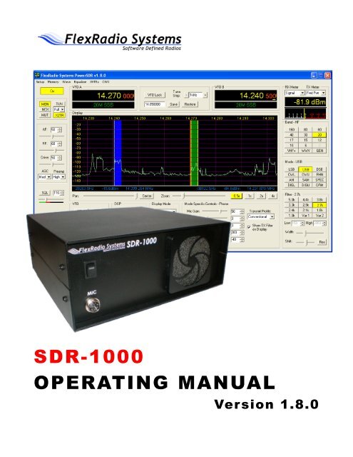
<strong>SDR</strong>-<strong>1000</strong>OPERATING MANUALVersion 1.8.0
S D R - 1 0 0 0 S O F T WA R E D E F I N E D R A D I O<strong>Operating</strong> <strong>Manual</strong>© FlexRadio Systems12100 Technology Boulevard • Austin, TX 78727Phone: (512) 250-8595 • Fax: (512) 233-5143Email: sales@<strong>flex</strong>-<strong>radio</strong>.<strong>com</strong>Editor: Joe de Groot – AB1DOi©FlexRadio Systems
T A B L E O F C O N T E N T SUniversal Controller Board for Antenna and Transverter Control............................................................9ENCLOSURE MICROPHONE CONNECTOR............................................................................... 10KEYER INPUT...................................................................................................................................115 HARDWARE SETUP...................................................................126 SOFTWARE INSTALLATION & SETUP........................................18INSTALL LATEST SOUND CARD DRIVERS................................................................................19UPGRADING FROM AN EARLIER VERSION..............................................................................19POWER<strong>SDR</strong> EXECUTABLE INSTALLATION............................................................................. 19POWER<strong>SDR</strong> SETUP WIZARD.........................................................................................................24SOUND CARD SETUP.......................................................................................................................33POWER<strong>SDR</strong> CALIBRATION...........................................................................................................34Frequency Calibration – DDS Clock Adjustment................................................................................. 35Auto Calibration............................................................................................................................ ..............35<strong>Manual</strong> Calculation................................................................................................................. ....................35Level Calibration – Spectrum & S-Meter............................................................................................. 35Image Null Calibration ....................................................................................................................... 36Automatic Calibration .................................................................................................................... .............36<strong>Manual</strong> Adjustment....................................................................................................................... ...............36AUTOMATIC AMPLIFIER GAIN CALIBRATION.......................................................................367 FRONT CONSOLE......................................................................38(1) VFO A............................................................................................................................................ 40(2) TUNING CONTROLS.................................................................................................................. 40(3) VFO B.............................................................................................................................................41(4) MULTIMETER............................................................................................................................. 41RX Meters.......................................................................................................................................... 41TX Meters.......................................................................................................................................... 42(5) BAND SELECTION & BAND STACKING MEMORIES..........................................................43(6) MODE SELECTION.....................................................................................................................44(7) FILTER CONTROLS................................................................................................................... 45Labeled Filter Buttons......................................................................................................................... 45Variable Filter Buttons........................................................................................................................ 46(8) MODE SPECIFIC CONTROLS...................................................................................................47Phone Controls ...................................................................................................................................47CW Controls.......................................................................................................................................48Digital Controls...................................................................................................................................50(9) DISPLAY CONTROLS.................................................................................................................50Panadapter View Controls................................................................................................................... 51Display Type Controls.........................................................................................................................52Display Type Descriptions.................................................................................................................. 52Spectrum..................................................................................................................................... ................53Panadapter (Panoramic Adapter)................................................................................................. ................53Histogram............................................................................................................................... ....................54iii©FlexRadio Systems
T A B L E O F C O N T E N T SWaterfall..................................................................................................................................................... .55Scope...................................................................................................................................... ....................55Phase............................................................................................................................................. .............56Off...................................................................................................................................... ........................56Cursor and Peak Position........................................................................................................................ .....57(10) SUB-RX CONTROLS..................................................................................................................58(11) DSP CONTROLS.........................................................................................................................58(12) VFO CONTROLS........................................................................................................................59(13) CPU %..........................................................................................................................................60(14) POWER (STANDBY/ON)........................................................................................................... 60(15) MON (MONITOR)...................................................................................................................... 61(16) MOX (MANUALLY OPERATED TRANSMIT).......................................................................61(17) MUT (MUTE).............................................................................................................................. 61(18) X2TR............................................................................................................................................ 61(19) ATU MODES............................................................................................................................... 62(20) TUN (TUNE)................................................................................................................................ 62(21) AF (AUDIO FREQUENCY GAIN).............................................................................................62(22) RF (RADIO FREQUENCY GAIN).............................................................................................63(23) DRIVE (TRANSMITTER POWER OUTPUT/TUNE POWER).............................................. 63(24) AGC (AUTOMATIC GAIN CONTROL)...................................................................................63(25) PREAMP......................................................................................................................................64(26) SQL (SQUELCH)........................................................................................................................ 64(27) DATE/TIME DISPLAY...............................................................................................................65(28) SETUP FORM............................................................................................................................. 65(29) – (33) OPERATING FORMS..................................................................................................... 658 SETUP FORM.................................................................. ...........66GENERAL TAB..................................................................................................................................67Hardware Config Sub-Tab.................................................................................................................. 67Radio Model................................................................................................................................................................67Hardware Setup............................................................................................................................................................68DDS.............................................................................................................................................................................69Options Sub-Tab.................................................................................................................................70Options........................................................................................................................................................................71Process Priority............................................................................................................................................................71Update Notification......................................................................................................................................................72Click Tune Offsets (Hz)................................................................................................................................................72Auto Mute....................................................................................................................................................................72Main Console (Always On Top)...................................................................................................................................73Keyboard.....................................................................................................................................................................73Calibration Sub-Tab............................................................................................................................ 74Freq Cal.......................................................................................................................................................................74Level Cal.....................................................................................................................................................................74RX Image Reject Cal...................................................................................................................................................75Filters Sub-Tab................................................................................................................................... 75AUDIO TAB........................................................................................................................................76Sound Card Sub-Tab...........................................................................................................................76Sound Card Selection...................................................................................................................................................76iv©FlexRadio Systems
T A B L E O F C O N T E N T SBuffer Size...................................................................................................................................................................76Sample Rate.................................................................................................................................................................77Line In Gain.................................................................................................................................................................77Mic In Gain..................................................................................................................................................................77Latency........................................................................................................................................................................77Output Voltage.............................................................................................................................................................77Sound Card Setup Details.............................................................................................................................................78VAC Sub-Tab.....................................................................................................................................79Gain (dB).....................................................................................................................................................................79Auto Enable.................................................................................................................................................................80DISPLAY TAB....................................................................................................................................80Spectrum Grid..............................................................................................................................................................81Refresh Rates...............................................................................................................................................................81Waterfall......................................................................................................................................................................82Multimeter...................................................................................................................................................................83Phase Resolution..........................................................................................................................................................83Scope Time Base..........................................................................................................................................................83Averaging....................................................................................................................................................................83Polyphase FFT.............................................................................................................................................................84DSP TAB............................................................................................................................................. 84Options Sub-Tab.................................................................................................................................84Noise Reduction...........................................................................................................................................................85Automatic Notch Filter.................................................................................................................................................85Buffer Size...................................................................................................................................................................86Noise Blanker..............................................................................................................................................................86Noise Blanker 2 ...........................................................................................................................................................87Image Reject Sub-Tab.........................................................................................................................90Receive Rejection........................................................................................................................................................90Transmit Rejection.......................................................................................................................................................91Keyer Sub-Tab....................................................................................................................................92CW Pitch.....................................................................................................................................................................92Connections.................................................................................................................................................................93Options........................................................................................................................................................................93Signal Shaping.............................................................................................................................................................94Semi Break In..............................................................................................................................................................94AGC/ALC Sub-Tab............................................................................................................................ 95AGC............................................................................................................................................................................95Leveler.........................................................................................................................................................................96ALC.............................................................................................................................................................................96TRANSMIT TAB................................................................................................................................97TX Profiles..................................................................................................................................................................98Transmit Filter..............................................................................................................................................................98Noise Gate...................................................................................................................................................................99VOX............................................................................................................................................................................99TX Monitor................................................................................................................................................................100Compression..............................................................................................................................................................100AM Carrier Level.......................................................................................................................................................101PA SETTINGS TAB..........................................................................................................................102Gain By Band (dB).....................................................................................................................................................102EXT. CTRL TAB.............................................................................................................................. 103APPEARANCE TAB ....................................................................................................................... 104Display Sub-Tab............................................................................................................................... 104v©FlexRadio Systems
T A B L E O F C O N T E N T SOverall Display..........................................................................................................................................................104Cursor/Peak Readout..................................................................................................................................................105Panadapter.................................................................................................................................................................105General Sub-Tab............................................................................................................................... 106VFO...........................................................................................................................................................................107Band Data..................................................................................................................................................................107Meter Sub-Tab..................................................................................................................................108Original Style.............................................................................................................................................................109Edge Style..................................................................................................................................................................109KEYBOARD TAB............................................................................................................................ 110CAT CONTROL TAB...................................................................................................................... 111Cat Control ................................................................................................................................................................112PTT Control...............................................................................................................................................................113Test............................................................................................................................................................................114TESTS TAB.......................................................................................................................................115TX IMD Text:............................................................................................................................................................115Audio Balance Test.....................................................................................................................................................115X2..............................................................................................................................................................................116Impulse Test...............................................................................................................................................................116Signal Generator.........................................................................................................................................................1169 OPERATING FORMS............................................................. ....117(29) MEMORY FORM..................................................................................................................... 118Save… .............................................................................................................................................118Recall…........................................................................................................................................... 119(30) WAVE FORM............................................................................................................................120Playback....................................................................................................................................................................120Playlist.......................................................................................................................................................................121Record.......................................................................................................................................................................121TX Gain (dB).............................................................................................................................................................121Record Options................................................................................................................................. 121Receive......................................................................................................................................................................122Transmit.....................................................................................................................................................................122(31) EQUALIZER FORM.................................................................................................................122(32) XVTRS FORM...........................................................................................................................123(33) CWX FORM.............................................................................................................................. 124Standard CWX Controls....................................................................................................................124CWX Memories............................................................................................................. ............................125Special Characters.......................................................................................................................... ...........125Keyboard and Extended Controls.......................................................................................................126Extended CWX Controls................................................................................................................ .............126Morse Definition Editor......................................................................................................................... .....12810 OPERATION................................................... ........................129POWER-UP PROCEDURE............................................................................................................. 130POWER-DOWN PROCEDURE......................................................................................................130TUNING METHODS........................................................................................................................131Spectrum Drag and Click.................................................................................................. .........................131vi©FlexRadio Systems
T A B L E O F C O N T E N T SMouse Wheel............................................................................................................................. ................131Mouse Wheel Hover....................................................................................................................... ............131Spectrum Click Tuning..................................................................................................... ..........................131Keyboard Keys........................................................................................................................................ ...132USB Tuning Knob.................................................................................................................. ....................132VOICE TRANSMISSION OPERATION........................................................................................ 133CW TRANSMISSION OPERATION.............................................................................................. 136Initial Settings................................................................................................................................... 137Internal Keyer................................................................................................................................... 138External Keyer.................................................................................................................................. 139CWX Form.......................................................................................................................................140Third Party Program..........................................................................................................................141DIGITAL MODE OPERATION......................................................................................................144CAT Control Setup........................................................................................................................... 147Install VCOM..................................................................................................................... .......................147Configure the VCOM Port Pairs............................................................................................... ..................153Configure Power<strong>SDR</strong> CAT Control........................................................................................... ..................155Configure Power<strong>SDR</strong> Keyer Connections........................................................................................... .........156Virtual Sound Connection................................................................................................................. 157Create the Virtual Audio Cables............................................................................................... ...................157Setup VAC in Power<strong>SDR</strong>........................................................................................................... .................158Setting up Third Party Digital Programs.............................................................................................158Using MixW with Power<strong>SDR</strong>............................................................................................................. .........159Programs Needing to Connect to the Default Sound Device........................................................... ...............164ATU (ANTENNA TUNING UNIT) OPERATION.......................................................................... 16611 TROUBLESHOOTING.............................................................168The software is oscillating quickly between receive and transmit modes..............................................168Relays do not click when starting the software or when cycling the software power button.................. 168Relays click, but I have no audio........................................................................................................173Relays click and I hear static, but no signals....................................................................................... 176I hear signals, but they sound chopped up, like a motorboat................................................................ 176I hear signals, but cannot null the image............................................................................................. 177The signals are all off frequency........................................................................................................ 178The noise hiss when no signals are present is fatiguing....................................................................... 178Software does not respond to PTT signals.......................................................................................... 178The receiver works great, but I am getting no output power................................................................ 179I am getting some power out, but the power seems low (also, see above—no power issue).................. 179I am getting signal reports that indicate echoing or distortion.............................................................. 180I am getting signal reports that indicate I am transmitting DSB while in SSB modes............................180I am getting an error message that says, “Error <strong>com</strong>municating with ATU.”........................................181It seems like the ATU is not tuning correctly. Is there a way to check?................................................ 181I get an error when I try to use my USB Adapter that says “USB Device not found. (-1)”.................... 182I see a hump around 10kHz below the center line on the display, that doesn’t seem to go away............182vii©FlexRadio Systems
PrefaceWel<strong>com</strong>e to the exciting world of software defined <strong>radio</strong>. The <strong>SDR</strong>-<strong>1000</strong> software defined transceiver is bynature ever (rapidly) evolving. It is therefore unlike most other transceivers, which once acquired, rarely ifever change.Although the rapid development of the <strong>SDR</strong>-<strong>1000</strong> can be exhilarating, it can also be somewhat daunting.1When first confronted with an <strong>SDR</strong>-<strong>1000</strong> and its Power<strong>SDR</strong> operating software, the sheer number ofconnections, controls, and settings can seem mind boggling even to the most seasoned Ham <strong>radio</strong> operator.This operating manual attempts to both guide a user step by step through the setup process (both hardwareand software) and to act as a reference once the <strong>radio</strong> has been set up. Additionally, the freely downloadablePower<strong>SDR</strong> software will install with default settings that, in most cases, will require little adjustment. Anyadjustments that you make are automatically saved and can be imported into an updated version of thesoftware.Due to the nature of the <strong>SDR</strong>-<strong>1000</strong>, the largest part of this operating manual, by far, will refer to software.The operating manual has numerous screenshots of windows and forms to detail the various steps.Although the manual describes the latest official release of the Power<strong>SDR</strong> software, you may occasionallynotice an earlier version identified in the title bar of a screenshot. This is because FlexRadio Systems2 hasdecided to only update a screenshot if it changes.The first three chapters of this manual will give you an overview of the <strong>SDR</strong>-<strong>1000</strong> <strong>radio</strong>. Chapters 4 and 5will guide you through the hardware setup, which apart from the connections to the parallel (or USB) portand sound card of a <strong>com</strong>puter, will not differ much from the transceivers to which you are most likelyalready acclimated.Chapter 6 details the installation of the Power<strong>SDR</strong> software and calibration routines. Once <strong>com</strong>pleted, youshould be able to engage in your first QSO. For additional guidance on operating the <strong>SDR</strong>-<strong>1000</strong> in variousmodes, you may want to refer to chapter 10: Operation. This is especially re<strong>com</strong>mended for operatingdigital modes and CW, as this may be somewhat different from what you are accustomed to.Chapters 7, 8, and 9 describe in detail the various controls on the Front Console, Setup Form and <strong>Operating</strong>Forms respectively. You may want to reference these chapters to familiarize yourself with the exactfunctioning of these controls and their often many options and settings.1Power<strong>SDR</strong> is a trademark of Bronze Bear Communications, Inc.2FlexRadio Systems is a registered trademark of Bronze Bear Communications Inc.viii©FlexRadio Systems
P R E F A C EFinally, chapter 11 is a troubleshooting guide, which should help you through various issues you may face.If you cannot find an acceptable answer to an issue you may have, please do not hesitate to contact us eitherby email or by phone (both found on our website). You may also want to check out our website and its everexpanding Knowledge BaseIf you have any ideas on how to improve the <strong>SDR</strong>-<strong>1000</strong>, please feel free to contact us, or better still, to joinour email reflector (see our website for details). Not only is the <strong>SDR</strong>-<strong>1000</strong> a software defined <strong>radio</strong>; it isalso a user defined <strong>radio</strong>.FlexRadio Systems is <strong>com</strong>mitted to ensuring that your experience with the <strong>SDR</strong>-<strong>1000</strong> will be one of themost enjoyable you have with Ham <strong>radio</strong>.[The rest of this page has been left blank intentionally]ix©FlexRadio Systems
AcknowledgmentsFlexRadio Systems could not be as successful, nor could the <strong>SDR</strong>-<strong>1000</strong> <strong>radio</strong> be what it is today withoutthe many selfless contributions of our users all over the world. These contributions have spanned andcontinue to span improvements to our hardware and software, ranging from bug reports and feature requeststo actual design and implementation of certain functionality.Identifying contributors by name would only risk leaving out others with equally valuable contributions.We therefore wish to suffice with a heartfelt thank you for your support and continued <strong>com</strong>mitment.[The rest of this page has been left blank intentionally]x©FlexRadio Systems
Chapter1General DescriptionThe <strong>SDR</strong>-<strong>1000</strong> Software Defined Radio is an open-software; 1 or 100Wtransceiver providing general coverage receive operation with amateur<strong>radio</strong> band transmission between 12kHz and 60MHz.The FlexRadio <strong>SDR</strong>-<strong>1000</strong> is a <strong>com</strong>plete Software Defined Radio (<strong>SDR</strong>) transceiver designed for AmateurRadio use. It is the first fully open software transceiver that uses a personal <strong>com</strong>puter (PC) for all DigitalSignal Processing (DSP) and control functions of the <strong>radio</strong>. General coverage receiver operation is providedfrom 12kHz to 60MHz along with transmit capability on all licensed amateur bands within the coveragerange. The theory behind the <strong>SDR</strong>-<strong>1000</strong> is described in detail in a four part QEX magazine series entitled,“A Software Defined Radio for the Masses 1 .” The articles are available for download from the FlexRadiowebsite at www.<strong>flex</strong>-<strong>radio</strong>.<strong>com</strong>. There are also links on the site to other excellent reference materials relatedto <strong>SDR</strong> and DSP theory.Since its introduction, additional hardware <strong>com</strong>ponents have been added to further improve thefunctionality and performance of the <strong>SDR</strong>-<strong>1000</strong>. The Power<strong>SDR</strong> TM software, written in C#.NET, provides afull featured transceiver interface and digital signal processing for the <strong>SDR</strong>-<strong>1000</strong>. It is continuouslyimproved over time through open source enhancements supplied by both customers and FlexRadioSystems.The basic hardware consists of four boards in a stack within an enclosure. The hardware provides a LNA,filters, mixer, power, i/o interfacing and 1W PEP driver. Also provided is a standard interface to theoptional Down East Microwave 2 meter low power transverter (intended for use in VHF, UHF, andMicrowave systems), as well as an interface to the optional 100W power amplifier and the ATU (LDG Z-100). Additionally available is an optional interface for an external, customer supplied 10 MHz referenceclock oscillator that may provide precision frequency control.The Contour ShuttlePro v2 USB controller offers the ability to control the <strong>radio</strong> the way you want towithout having to use a mouse or keyboard. With 15 programmable buttons and 2 concentric tuning dials(one spring loaded jog dial), this accessory offers an unparalleled level of programmable hardware control.1G. Youngblood, “A Software Defined Radio for the Masses: Part 1, Part 2, Part 3, and Part 4,” QEX Jul/Aug 2002, Sep/Oct 2002,Nov/Dec 2002, and Mar/Apr 2003 respectively.1 ©FlexRadio Systems
Chapter2Specifications(Specifications are subject to change without notice)Table 1: SpecificationsReceiverReceiver Frequency Range 12kHz-60MHz 1IP3 (2kHz Tone Spacing) +30.3dBm (Preamp MED), 19.3dBm (Preamp HIGH) 2IMD DR3 (2kHz Tone Spacing) 103.5dB (Preamp MED), 100.2dB (Preamp HIGH) 2MDS -131dBm (Preamp HIGH), -121dBm (Preamp MED) 2Minimum Tuning Step1Hz (DDS down to µHz)DDS Clock200MHz,
Chapter3Hardware ConfigurationStandard ConfigurationHigh Performance Receiver PreamplifierThe receiver front end incorporates a Sirenza Microdevices SGA-6286 SiGe HBT MMIC amplifier with anoise figure of less than 2dB. With the INA baseband gain of the <strong>SDR</strong>-<strong>1000</strong> set to 26dB, the overallreceiver noise figure is approximately 4dB. The TRX board also allows 0dB INA gain setting for largesignal handling capability. A 10dB fixed attenuator may be switched in front of the LNA to increase IP3when needed. Overall there are four gain settings done in hardware to allow you to optimize the front endfor your needs.The front end of the <strong>SDR</strong>-<strong>1000</strong>, provides the following key benefits:Lower receiver noise figureReduces relative strength of DDS local oscillator spurs in relation to the signal of interestLowers local oscillator radiation in relation to the signal of interestFixed source/load impedance for the filtersFixed source impedance for the QSD (Quadrature Sampling Detector, IQ Mixer)Fifth Order Low Pass FiltersNine 5th order low pass filter banks are provided to cover all amateur bands from 160M-6M. Since thefilters are low pass, general coverage reception is still provided. The filters improve 3rd harmonic rejectionby more than 35dB over the original <strong>SDR</strong>-<strong>1000</strong>. There are BPF filters in front of the preamp board (in thesignal chain) to provide overload protection for the LNA. The LNA is then followed by the low pass filters,which in turn drive the QSD (mixer) on the TRX board. A spare filter bank is provided for userconfiguration to allow improved coverage on other bands such as medium wave or VLF bands. While the<strong>SDR</strong>-<strong>1000</strong> covers frequencies down to 11kHz, additional filtering is required to minimize response to oddorder harmonics. The optional filter bank allows the user to customize the <strong>radio</strong> to add support for suchfrequencies.3 ©FlexRadio Systems
H A R D W A R E C O N F I G U R A T I O N C H A P T E R 3Enhanced 1W PEP DriverThe low power model incorporates a 1W PEP driver amplifier. The driver is between the new front end lowpass filters and the band pass filters on the BPF board, which yields increased harmonic suppression. Thedriver circuit also allows for amplifier stability when driving capacitive loads and increases the gain toreduce sound card drive requirements.28MHz Transverter IF TakeoffThe RFE provides an internal connector for integration of the Down East Microwave 2M transverter IF(DEMI144-28FRS). Only a single coax cable is required for both RF and TR control. The <strong>SDR</strong>1K-ENCenclosure has mounting holes to allow either <strong>com</strong>mon or separate transmit/receive connections fortransverters. You can even set up the <strong>SDR</strong>-<strong>1000</strong> to provide a dual 144/28MHz IF to cover all of the VHFthrough microwave bands.Key features of the DEMI144-28FRS are:144-146MHz coverageUnity gain receive conversion4dB NF maximum+17dBm double balanced mixerThree chamber helical filter100mW nominal linear outputExperimental Impulse GeneratorAn experimental circuit has been incorporated that creates a 4.5ns pulse for equalization of the QSD andsound card quadrature path. DSP software will be written to calculate the impulse response of the circuitand automatically correct for phase and amplitude imbalances between the channels. In theory, this willprovide dynamic opposite sideband rejection optimization.EnclosureThe <strong>SDR</strong>1K-ENC enclosure is designed to ac<strong>com</strong>modate expansion options including the Down EastMicrowave 2M IF transverter and the 100W PEP HF linear amplifier and LDG Z-100 automatic antennatuning unit options. Rear panel connections are provided for the PC parallel control port, sound cardinterface, 7 external control lines, split or <strong>com</strong>mon transverter RF connections, and QRP and QRO RFconnections. An AUX mounting hole is provided for the 10MHz reference clock option connector whenprecision frequency control is desired.4 ©FlexRadio Systems
H A R D W A R E C O N F I G U R A T I O N C H A P T E R 3Upgrades2 Meter TransverterThe DEM 144-28FRSK is a low power, high performance 144 MHz to 28 MHz transverter kit design to beused in conjunction with Flex Radio System’s <strong>SDR</strong>-<strong>1000</strong> Software Defined Radio transceiver. It is intendedto be used as a 2nd conversion IF for microwave transverters. The 144-28FRSK has a nominal linear outputpower of 50 - 100 mW with the 28 MHz. IF drive provided by the <strong>SDR</strong>-<strong>1000</strong>. On the receive side, a highdynamic range amplifier, a high level double balanced mixer (+17.0 dBm) and a three chamber helical filterare employed to providing a over load proof, unity gain front end with superior selectivity. It is the samedesign as our high performance 2 meter transverter but without the GaAs FET front end that would provideexcessive system gain not require in a microwave transverter system. The transverter is <strong>com</strong>plete with allinterfacing required to install in the <strong>SDR</strong>1K-ENC enclosure and operate with the <strong>SDR</strong>-<strong>1000</strong>.The 144-28FRSK’s 144 MHz input/output utilize BNC connectors (supplied in this kit) that are mounted inthe existing holes in the <strong>SDR</strong>1K-ENC enclosure. The transverter also has a built in relay for externalswitching duties if required. It will “Shadow” the TR switch timing of the <strong>SDR</strong>-<strong>1000</strong>. The only externalwiring required to operate a microwave transverter after the <strong>com</strong>pletion of this kit are a simple BNC cableor cables that will carry both TX and RX signals along with the keying voltage to activate the microwavetransverters of choice transmit functions. It is a <strong>com</strong>plete, simple to use kit and will provide the highest 2meter to microwave transverter performance on the market today.100W Power AmplifierThe <strong>SDR</strong>-100WPA is a 100 Watt HF linear power amplifier, designed exclusively for installation in <strong>SDR</strong>-<strong>1000</strong> Software Defined Transceivers. Adding the 100WPA to existing <strong>radio</strong>s required limited kit buildingskills including wire/coax preparation, connector assembly, soldering, and mechanical assembly.SpecificationsPower output: 100W PEP, 50W on 60mBands: 160, 80, 60, 40, 30, 20, 17, 15, 12, 10 metersElliptical filters on all bandsDrive requirements:
H A R D W A R E C O N F I G U R A T I O N C H A P T E R 3Software monitoring: Forward/Reverse Power and SWR SWR protection: automatic power reduction for SWR > 2:1DC power requirements: 13.8VDC @ 25A nominal for full outputInternal fuse: 25A automotive mini fuse with reverse polarity protectionOutput: BNC 50 Ohm on rear panelCooling: 80x80x15mm, 23dB-A fan providedInternal expansion connections: ATU RF In/Out and controlAutomatic Antenna Tuning UnitThe <strong>SDR</strong>-ATU is a fully integrated automatic antenna-tuning unit across the entire HF range. It will tunedipoles, verticals, Yagis or virtually any coax-fed antenna. It will match a wide range of antennas andimpedances. Features include:Microprocessor controlled, switched L tuning networkAutomatically matches antennas from 6-800 ohms impedance, or a 10:1 SWR, 3:1 on 6mTunes from memory in less than one half second. A full tune will take from 1-6 seconds.200 memories for almost instant return of previously tuned frequencies.Continuous coverage from 1.8 to 54 MHzPower range 0.1 to 125 Watts, 50 Watts on 6mGriffin PowerMate TM VFO Tuning KnobThe attractive GCN-SLV Griffin Technology PowerMate control knob connects to a USB port to providevariable-rate VFO tuning for the <strong>SDR</strong>-<strong>1000</strong>. A simple click of the knob changes the tuning rate to any offour user configured tuning rates. It can even be programmed to set the volume by a press, hold, and turn ofthe knob. Made of high-quality machined aluminum, PowerMate feels like a solid volume knob pulled rightoff the front of a world-class stereo. Its heavy weight and tactile feel are a wel<strong>com</strong>e departure from typicalplastic USB peripherals.Contour Designs Shuttle Pro V.2The ShuttlePro V.2’s sleek innovative design, pre-configured for many of today's popular applications,advanced programmability, and ease of use is in short, the perfect marriage of form and function.6 ©FlexRadio Systems
H A R D W A R E C O N F I G U R A T I O N C H A P T E R 3The ShuttlePro V.2 is a powerful productivity enhancement tool for the Power<strong>SDR</strong> software. TheShuttlePro V.2 even <strong>com</strong>es pre-configured for many of the leading applications. You can also easilycustomize the ShuttlePro V.2 for virtually any application.The ShuttlePro V.2 is designed for ergonomic integrity and maximizing productivity, allowing one-handaccess to the fully programmable buttons and jog/shuttle knob. Nine (9) of the buttons have removablekeycaps for easy labeling and referencing. The inner ring or 'jog' rotates through 360 degrees and providesprecision control. The outer black ring or 'shuttle' is rubberized and spring-loaded. It facilitates tuning and<strong>radio</strong> control. You can also use the jog and shuttle for many other purposes such as scrolling, volumecontrol, and sequencing.External Clock Reference OptionThe <strong>SDR</strong>-CLK External Clock Reference Option kit provides the connection required to operate the DDSoscillator from an external 10MHz or 20MHz precision frequency reference. GPS locked oscillators may beused in this configuration to provide precise frequency control of the <strong>SDR</strong>-<strong>1000</strong>. The internal 200MHzoscillator must be removed to use the external reference clock.Note:This option requires a customer provided precision clock source notprovided by FlexRadio Systems.USB To Parallel AdapterThe <strong>SDR</strong>-USB is a USB to parallel <strong>com</strong>munications adapter, specially designed to control the <strong>SDR</strong>-<strong>1000</strong>. Itallows the <strong>radio</strong> to be used with <strong>com</strong>puters that do not have a parallel port available. The <strong>SDR</strong>-USBsupports all of the control and status lines required by the <strong>SDR</strong>-<strong>1000</strong> and has special firmware to offloadhardware polling tasks from the PC. A separate download and installation of driver software is required.[The rest of this page has been left blank intentionally]7 ©FlexRadio Systems
Chapter4Plug PinoutsExternal Control Connector (X2)The 15-pin, high-density, female “D” connector is found on the rear panel. It offers seven open collectorDarlington outputs that allow control of external devices such as transverters, relays, antennas, poweramplifiers, etc. It also includes two dedicated push-to-talk (PTT) inputs (Pins 10 & 11 – see below). Theconnector has 5VDC power at up to 50mA for powering external relays or logic. The open collector outputsmay also be used with external power supplies up to a maximum of 50VDC. The maximum collectorcurrent for a single output is 500mA. A <strong>com</strong>mon output clamp diode return is provided (Pin 8) to handlerelay transients. The table below details the pin connections. If you prefer not to hand-wire the connector forany reason, cut the end off a VGA PC monitor cable and use its respective leads.Table 2: X2 Pin Connections and DiagramPin # Function Specification Diagram1 Control 1 Open Collector – 50V, 500mA Max.2 Control 2 Open Collector – 50V, 500mA Max.3 Control 3 Open Collector – 50V, 500mA Max.4 Control 4 Open Collector – 50V, 500mA Max.5 Control 5 Open Collector – 50V, 500mA Max.6 Control 6 Open Collector – 50V, 500mA Max.7 PTT Output (PA Control)* Open Collector – 50V, 500mA Max.8 Common Protection Diode Connect to Relay + Supply9 Not Connected Not Connected10 PTT Input (Secondary)SSB/AM/FM only (no CW) – Groundthis line to key transmitter11 PTT Input (Main) [S3]Works in all modes – Ground thisline to key transmitter12 Software Audio Mute** Pull to ground to Mute the receiver.13 Not Connected Not Connected14 Vcc 5VDC Output @ 50mA15 Ground Signal Ground for all inputs/outputs* Requires enabling X2 TR Sequencing on the Setup Form - General Tab, Options Sub-Tab.** Requires enabling Auto Mute on the Setup Form - General Tab, Options Sub-Tab.8 ©FlexRadio Systems
P L U G P I N O U T S C H A P T E R 4Push To Talk (PTT) InputThe External Control (X2) connector has two PTT input connections as seen in Table 1 above. Pin 11works in all modes, while Pin 10 works only in voice modes. Pin 11 is re<strong>com</strong>mended for most applications.PTT is activated by grounding to Pin 15 either of the two respective pins.Mute ReceiverThe External Control (X2) connector has a pin dedicated to muting the receiver for multiple transceiveroperation. Simply ground Pin 12 to Pin 15 to activate the software MUT (Mute) control. Note that this doesnot disconnect the coaxial connector from the receiver. External antenna switching is necessary to ensurethat high power signals are not sent directly to the <strong>SDR</strong>-<strong>1000</strong> receiver front end.External Linear Amplifier KeyingExternal linear amplifiers may be keyed using Pin 7 on the External Control (X2) connector. Mostamplifiers are switched by grounding its keying input. Connect Pin 7 (PTT Output) to the hot lead of keyinginput and Pin 15 to the amplifier ground. This output uses an open collector Darlington transistor switchthat is rated at 500mA, 50VDC maximum.To ensure that your amplifier keying circuit does not damage the Darlington transistor switch, insert thecircuit shown in the figure below between Pins 7 and 15 on X2 and your amplifier.Figure 1: Protective PTT Circuit Between <strong>SDR</strong>-<strong>1000</strong> and AmplifierUniversal Controller Board for Antenna and Transverter ControlThe Universal Controller Board (UCB) is a customer developed and supplied accessory that connects to theExternal Control (X2) connector. It allows automatic software control of up to 16 antennas and/ortransverters.The Universal Controller Board is an extension of the <strong>SDR</strong>-<strong>1000</strong> to enable additional control of externaldevices by the <strong>radio</strong>. The <strong>SDR</strong>-<strong>1000</strong> X2 connector provides 6 open collector output pins for user definedfunctions. The purpose of the UCB is to accept data from the <strong>SDR</strong>-<strong>1000</strong> via the X2 connector to be loadedinto a 16X16 memory matrix on the UCB. Pins 1 through 4 of the X2 connector are used as an address fieldby the UCB to address one of 16 registers within the memory matrix. Each one of these UCB registers has9 ©FlexRadio Systems
P L U G P I N O U T S C H A P T E R 416 bits, of which any <strong>com</strong>bination can be operational. Each bit in a register corresponds to a relay that willbe picked.Enclosure Microphone ConnectorA front panel connector is provided for microphone and push-to-talk (PTT) input. Depending on when your<strong>radio</strong> shipped, the connector will be a 4 or 8 pin connector. See the table below for the pinouts for each ofthese connectors. The PTT input must provide a contact closure to ground to activate the transmitter.The 8-pin microphone configuration offers the ability to connect a balanced microphone through the frontpanel connector. Keep in mind that it is possible to plug a microphone directly into either of ourre<strong>com</strong>mended sound cards (Delta-44 and Edirol FA-66). They both offer ¼” connectors and the Edirol FA-66 has true balanced inputs along with XLR connectors and adjustable Mic Preamps.Radios shipped after January 11, 2006 have an 8-pin connector. Radios shipped before that date have a 4-pin connector, but the wiring configuration of this connector has been modified on all <strong>radio</strong>s shipped afterFebruary 4, 2005 from those shipped before that date. The following table shows the pin connections andthe wiring configurations.Table 3: Microphone Connector ConfigurationsShip Date Pin # Signal Diagram1 Not Connected2 Not Connected3 Not ConnectedAfter4 Not ConnectedJan 11 20065 Chassis GND (Shield)6 PTT (+)7 Mic (–)8 Mic (+)BeforeJan 11 2006,AfterFeb 4 2005BeforeFeb 4 20051 Mic (+)2 Mic (-)3 PTT (+)4 PTT (-)1 Ground2 Microphone Audio3 Push To Talk4 No ConnectionWe re<strong>com</strong>mend use of the Heil microphones, especially the PR series; however, the HM-10 and Goldlinemicrophones will also work well with the <strong>SDR</strong>-<strong>1000</strong>.Use the procedure found in the Voice Transmission Operation section in order to match the microphoneappropriately with the sound card and the DSP.10 ©FlexRadio Systems
P L U G P I N O U T S C H A P T E R 4Keyer InputTo connect either a keyer or straight key to the Key jack on the rear panel use the following table. While thekeyer input lines can be reversed on the Setup Form-DSP Tab, Keyer Sub-Tab, we are including this pinoutfor <strong>com</strong>pleteness.Table 4: Key Plug PinoutConnectorKeyerSignalStraightKeyTip Dot KeyRing Dash KeySleeve Common CommonNote 1:Note 2:Using a mono 2-conductor type plug will cause problems as the Ring willbe shorted to the Sleeve (Key to Common or Dash to Common dependingon setup).For optimal (low latency) performance, connect your paddles or keyerdirectly to a serial port on the PC using the following table. Also see thesection on the Setup Form-DSP Tab, Keyer Sub-Tab.Table 5: PC Serial Port PinoutSerialPort Pin* Keyer Signal4 (DTR) Common6 (DSR) Dot8 (CTS) Dash* Assumes a 9-Pin connector[The rest of this page has been left blank intentionally]11 ©FlexRadio Systems
Chapter5Hardware SetupThe hardware setup process is as simple as making connections from the <strong>SDR</strong>-<strong>1000</strong> enclosure to thehardware necessary to run the <strong>radio</strong> (power supply, antenna, parallel port, and sound card). Refer to thenumerical callouts in Figure 3 below for the location of all <strong>radio</strong> connections.Make sure the power switch on the front panel of the enclosure is in the Off (down – “O” on some models)position. Connect the power supply negative (1) and positive (2) leads to the black (--) and red (+) powersupply connectors respectively. Ensure that correct polarity is maintained as reversing the cables can causedamage to the unit. The power supply must provide 13.8VDC at 25A (nominal) for the 100W transceiverand 1.5A for the 1W transceiver respectively.Make a low impedance connection to earth (RF) ground (8) to properly protect the unit.Connect the PC parallel port to the parallel connector (10) on the enclosure. Use a 25-pin, male-to-maleparallel cable that has all 25 pins connected straight through. These are called RS-232 cables by somemanufacturers. Both parallel and audio cables are available from FlexRadio Systems. Make sure theconnection is firm as a partial parallel connection can cause sporadic frequency tuning and filter selection.Note:FlexRadio Systems distinguishes between re<strong>com</strong>mended, legacy andunsupported sound cards. Re<strong>com</strong>mended cards are actively supportedand used for system development. Legacy cards are those cards that werepreviously re<strong>com</strong>mended and are now only passively supported.Unsupported cards include all other sound cards. From time to timeFlexRadio Systems will adjust a sound card’s designation; the most up-todateinformation is available on our website.FlexRadio Systems currently re<strong>com</strong>mends two sound cards for use with the <strong>SDR</strong>-<strong>1000</strong>: The M-AudioDelta-44 is the re<strong>com</strong>mended PCI interface and the Edirol FA-66 is the re<strong>com</strong>mended Firewire (1394)interface card (ideal for laptop connection). Each of these professional grade sound cards offers multipleinputs and outputs which allows us to mix separate monitor and <strong>radio</strong> outputs as well as leave the <strong>radio</strong> andmicrophone connected to the inputs. The audio quality of these re<strong>com</strong>mended cards is also superior to anyof our legacy (previously re<strong>com</strong>mended) cards as these legacy cards were all consumer grade. Please referto the charts and tables on the specifications page of the website that show the superior dynamic range andnoise performance of our re<strong>com</strong>mended cards. This is a clear-cut example of professional quality audio12 ©FlexRadio Systems
H A R D W A R E S E T U P C H A P T E R 5equipment (M-Audio) versus consumer quality equipment (Creative). The gap between the two issubstantial.Connect the sound card to the <strong>radio</strong> as follows. Please consult the Delta-44 Quick Start Guide or the EdirolFA-66 Quick Start Guide. For other cards proceed as follows: First, connect the Line In cable from thesound card Line Input (usually color coded blue) to the plug labeled “To Line In” (14) on the back of the<strong>radio</strong>. Next, connect the Speaker output from the sound card (usually color coded light green) to the pluglabeled “To Line Out” (12). Make sure that if your sound card has multiple speaker outputs you use the onelabeled Speaker 1 (or the “front” speakers).Note:For certain legacy sound cards, it is necessary to install the <strong>SDR</strong>-LPF/CBL low pass filter on the Line Out connection to prevent widebandnoise transmission. The re<strong>com</strong>mended sound cards, Delta-44 and EdirolFA-66, do not require this filter.Some sound cards, such as the Turtle Beach Santa Cruz and Audigy2 ZS,emit noise that peaks in the 100kHz range and must be suppressed to<strong>com</strong>ply with FCC rules (-43dBc). Instructions for making the <strong>SDR</strong>-LPF/CBL can be found on the FlexRadio Private Download Page. Thecable must be installed with the filter module nearest to the <strong>radio</strong>.Reversing the cable will not allow the filter to operate properly.If you have any questions regarding the need to use this filter for yoursound card, please contact FlexRadio Systems.Then connect the Microphone Input from the sound card (usually color coded red) to the plug labeled “ToMic In” (15). Note that this is only necessary if using a microphone connected to the front panel of theenclosure. If using a PC mic, this can be plugged directly into the sound card. Finally, connect amplifiedspeakers to the plug marked SPKR (13). Note that using non-powered speakers or low impedanceheadphones will load down the transmitter drive to the <strong>radio</strong>, thereby preventing full power output.This is not an issue with 4-port cards such as the Delta-44 and the FA-66 since the output does notrun through the <strong>radio</strong>.Note:It is critical that the audio cables used to connect to the sound card areseated flush against the back panel of the enclosure to provide goodcontact for the stereo input and output. Failure to do so will preventopposite sideband rejection on both reception and transmission. Cableswith wide connector ends are the cause of this issue in most instances.Premium “Gold” cables are NOT re<strong>com</strong>mended because they aretypically overpriced and their connectors are usually too large.13 ©FlexRadio Systems
H A R D W A R E S E T U P C H A P T E R 5If the 100W amplifier is included, connect the HF/6m antennas to the HF/PA (3) connector. WHEN THE100W AMPLIFIER IS INSTALLED, DO NOT CONNECT ANYTHING TO THE HF/50 MHZQRP CONNECTOR. This connector is in parallel with the input to the power amplifier. If the amplifier isnot installed, connect the antenna to the HF/50 MHz QRP connector for the 1W output configuration.If the DEMI144-28FRS 2m transverter is installed, its connection(s) go to (6) / (7). Please see thetransverter’s installation instructions for connector options that allow for <strong>com</strong>mon or split TX/RX. Also, ifusing the external clock reference option, connect the reference signal to (4).Note 1:Note 2:If the 100W amplifier is installed, the AUX hole is covered by theamplifier hardware and the reference connector will be moved to anotherlocation (possibly to 6 or 7 if the transverter is not installed).If the amplifier is installed, it is necessary to uncheck the box that enablesthe PA on the Setup Forms General Tab before attempting to transmitQRP. If the amplifier is disabled in software, the 1W transmitter will beconnected straight through to the HF/PA connector. The output on 6m isalways QRP since the PA does not cover 6m.Finally, connect any external hardware control lines (linear amplifiers, transverters, or relays) to the X2connector (9) as defined in the section on Plug Pin Out above.[The rest of this page has been left blank intentionally]14 ©FlexRadio Systems
H A R D W A R E S E T U P C H A P T E R 515 ©FlexRadio Systems
H A R D W A R E S E T U P C H A P T E R 5Connections are as follows:Figure 2: Back Panel of Enclosure(1) Power Ground - #12AWG or greater for 100W version.(2) 13.8VDC Power - #12AWG or greater for 100W version.(3) 100W Power Amplifier Antenna Connector – Use for all bands if 100W amplifier is installed.(4) Auxiliary Input Connector for optional External Reference Oscillator.(5) 1W QRP Antenna Connector – Use ONLY if 100W amplifier is NOT installed (when installed,this connector is in parallel with the amplifier input circuit.(6) Two Meter Transverter Transmit Connector – Used for split transmit/receive operation (SeeDEMI144-28FRS installation instructions).(7) Two Meter Transverter Receive or Receive/Transmit Common Connector – (See DEMI144-28FRSinstallation instructions).(8) Earth (RF) Ground.(9) X2 External Control Connector – See Table 1 for connections.(10) Parallel Port Connector (to PC parallel port) – Optional <strong>SDR</strong>-USB USB to Parallel Adapterconnects to this port.(11) Code Key/Paddles Connector – See previous chapter for connection.16 ©FlexRadio Systems
H A R D W A R E S E T U P C H A P T E R 5Hint:For optimal (low latency) performance connect the key or paddles to a PCserial port instead (see the section on the Setup Form-DSP Tab, KeyerSub-Tab in chapter 8 for more information).(12) To Line Out (speaker output) on Sound Card – Green color-coded.(13) To Amplified Speaker or high impedance headphones.Note:Do not use if using one of our re<strong>com</strong>mended sound cards (Delta-44 orEdirol FA-66). Instead for best performance and to enable monitoring,connect your speaker(s) directly to the sound card.(14) To Line In on Sound Card – Blue color-coded.(15) To Microphone Input on Sound Card -- Pink or Magenta color-coded. (This connector is directlyconnected to the corresponding pins on the front panel mic connector.)[The rest of this page has been left blank intentionally]17 ©FlexRadio Systems
Chapter6Software Installation & SetupWARNING! Proper operation of the <strong>SDR</strong>-<strong>1000</strong> depends on the use of a soundcard that is officially re<strong>com</strong>mended by FlexRadio Systems. Refer tothe Specifications page on www.<strong>flex</strong>-<strong>radio</strong>.<strong>com</strong> to determine whichsound cards are currently re<strong>com</strong>mended. Use only the specific modelnumbers stated on the website because other models within the samefamily may not work properly with the <strong>radio</strong>. Officiallyre<strong>com</strong>mended sound cards may be updated on the website withoutnotice. If you have any question about the sound card you would liketo use with the <strong>radio</strong>, please email support@<strong>flex</strong>-<strong>radio</strong>.<strong>com</strong> or call usat 512-250-8595.NO WARRANTY IS IMPLIED WHEN THE <strong>SDR</strong>-<strong>1000</strong> IS USEDWITH ANY SOUND CARD OTHER THAN THOSECURRENTLY RECOMMENDED AS STATED ON THEFLEXRADIO SYSTEMS WEBSITE. UNRECOMMENDEDSOUND CARDS MAY OR MAY NOT WORK WITH THE <strong>SDR</strong>-<strong>1000</strong>. USE OF UNRECOMMENDED SOUND CARDS IS AT THECUSTOMERS OWN RISK.[The rest of this page has been left blank intentionally]18 ©FlexRadio Systems
S O F T W A R E I N S T A L L A T I O N & S E T U P C H A P T E R 6Install Latest Sound Card DriversDownload the latest sound card drivers from the manufacturer. Install the software using the “Driver Only”option if there is one.Note 1:Note 2:Using the “Driver Only” option (Audigy 2 ZS, and others) will preventsome software from loading programs that will engage audio effects suchas Reverb or Echo by default. This causes problems with the receiveand/or transmit performance of the <strong>radio</strong>. All such sound card audioeffects should be turned off to prevent problems with the <strong>radio</strong>.If using a legacy sound card (or an unsupported sound card without nativeASIO drivers) you will need to install ASIO4ALL, which can be foundon the Downloads page of our website. If using one of our re<strong>com</strong>mendedsound cards (M-Audio Delta-44 or Edirol FA-66), installing ASIO4ALLis unnecessary.Upgrading From an Earlier VersionIt is re<strong>com</strong>mended that you leave older versions of the Power<strong>SDR</strong> console installed when upgrading from aprevious version. After reviewing the new version and verifying that your setup works, uninstallingprevious versions is fine (but not necessary). Note that it is necessary to manually delete the database file(Power<strong>SDR</strong>.mdb) from the application directory (usually c:\Program Files\FlexRadio Systems\Power<strong>SDR</strong> x.y.z) in order to <strong>com</strong>pletely remove previous versions.Power<strong>SDR</strong> Executable InstallationDownload the latest Power<strong>SDR</strong>_x.y.z.zip to a directory on your hard drive (saving to the Desktop isre<strong>com</strong>mended) and unzip the contents. Double click the Setup file (Setup.exe) to start the installationprocess. The Power<strong>SDR</strong> installation will prompt you to install the .NET framework if it is not installed andit will point you to the appropriate web address for downloading as seen below.Figure 3: Prompt for .NET Framework19 ©FlexRadio Systems
S O F T W A R E I N S T A L L A T I O N & S E T U P C H A P T E R 6Follow the instructions to install the framework using the download from Microsoft’s website and thenrestart the Setup.exe program. You should see the following screen.Click the Next button to continue.Figure 4: Power<strong>SDR</strong> Installation Wel<strong>com</strong>e Screen[The rest of this page has been left blank intentionally]20 ©FlexRadio Systems
S O F T W A R E I N S T A L L A T I O N & S E T U P C H A P T E R 6Figure 5: Power<strong>SDR</strong> Installation Folder SelectionYou can change the installation directory here, though we re<strong>com</strong>mend you use the default fortroubleshooting purposes. Click the Next button to continue.[The rest of this page has been left blank intentionally]21 ©FlexRadio Systems
S O F T W A R E I N S T A L L A T I O N & S E T U P C H A P T E R 6Figure 6: Power<strong>SDR</strong> Installation License AgreementRead the GNU Public License. If you accept, click I Agree and click the Next button to continue.Otherwise click Cancel.[The rest of this page has been left blank intentionally]22 ©FlexRadio Systems
S O F T W A R E I N S T A L L A T I O N & S E T U P C H A P T E R 6Figure 7: Power<strong>SDR</strong> Installation ConfirmationClick the Next button to confirm these settings and to copy the necessary files to the selected installdirectory. Once the files have been copied, you will see the following screen.[The rest of this page has been left blank intentionally]23 ©FlexRadio Systems
S O F T W A R E I N S T A L L A T I O N & S E T U P C H A P T E R 6Figure 8: Power<strong>SDR</strong> Installation CompleteClick the Close button to <strong>com</strong>plete the installation and close the dialog.Power<strong>SDR</strong> Setup WizardBefore powering up the <strong>radio</strong> hardware, load the Power<strong>SDR</strong> console using the shortcut on the Desktop (orin the Start menu). When you run (a new release of) Power<strong>SDR</strong> for the first time an optimization routinewill run and the following screens will appear:[The rest of this page has been left blank intentionally]24 ©FlexRadio Systems
S O F T W A R E I N S T A L L A T I O N & S E T U P C H A P T E R 6Click OK and let the routine run.Figure 9: Optimization RoutineNote:This routine aims to optimize the FFT calculations for the environment(hardware and software) in which the calculations will be performed. Foroptimal performance, you should therefore close all applications you willnormally not be running simultaneously with Power<strong>SDR</strong>. The routinewill save a file called wisdom to the directory in which Power<strong>SDR</strong>resides. If you wish to run FFTW again, delete this file from the directoryand start up Power<strong>SDR</strong>.When the routine has <strong>com</strong>pleted a brief startup sequence will follow, after which you should be greeted bythe Power<strong>SDR</strong> Setup Wizard as shown in the figure below.[The rest of this page has been left blank intentionally]25 ©FlexRadio Systems
S O F T W A R E I N S T A L L A T I O N & S E T U P C H A P T E R 6Click the Next button to continue.Figure 10: Power<strong>SDR</strong> Setup Wizard Wel<strong>com</strong>eFigure 11: Power<strong>SDR</strong> Setup Wizard - Database ImportClick the Yes or No button to indicate whether you would like to import a database from a previous version(assumes you are upgrading). If yes, click the Select File … button and select the Power<strong>SDR</strong>.mdb file froma previous version (default directory is C:\Program Files\FlexRadio Systems\Power<strong>SDR</strong> x.y.z\). A prompt26 ©FlexRadio Systems
S O F T W A R E I N S T A L L A T I O N & S E T U P C H A P T E R 6will confirm that the database file was imported successfully as seen in the screenshot below. Click the OKbutton.Figure 12: Successfully Imported Database PromptClick the Next button to continue. If you imported a database, the rest of the steps will be skipped and youwill jump straight to the finished screen.Figure 13: Power<strong>SDR</strong> Setup Wizard - Radio ModelSelect the <strong>radio</strong> model you will be using. If you are running without any <strong>radio</strong>, e.g. for demonstrationpurposes, select Demo/None. Click the Next button to continue.[The rest of this page has been left blank intentionally]27 ©FlexRadio Systems
S O F T W A R E I N S T A L L A T I O N & S E T U P C H A P T E R 6Figure 14: Power<strong>SDR</strong> Setup Wizard – RFESelect the Yes or No button to indicate whether your configuration includes the RF Expansion Board(RFE), and click the Next button to continue.Note:All <strong>SDR</strong>-<strong>1000</strong>s shipped since 2005 include the RFE board.Figure 15: Power<strong>SDR</strong> Setup Wizard - 2m XVTR28 ©FlexRadio Systems
S O F T W A R E I N S T A L L A T I O N & S E T U P C H A P T E R 6Select the Yes or No button to indicate whether your configuration includes the optional 2m transverter. Ifyes, select your model using the drop down box. Note that FlexRadio Systems only sells the DEMI144-28FRS model. It uses negative logic keying on the coax to the transverter. Click the Next button tocontinue.Figure 16: Power<strong>SDR</strong> Setup Wizard – PASelect the Yes or No button to indicate whether your configuration includes the 100W Power Amplifier. Ifyes, enter the gain values found on the sheet included with the amplifier shipment. Click the Next button tocontinue.Note:If you have a dummy load, you should run the Automatic Amplifier GainCalibration (see later in this chapter) in your own environment for the bestcalibration.[The rest of this page has been left blank intentionally]29 ©FlexRadio Systems
S O F T W A R E I N S T A L L A T I O N & S E T U P C H A P T E R 6Figure 17: Power<strong>SDR</strong> Setup Wizard – ATUClick the Yes or No button to indicate whether you have the integrated ATU installed. Click Next tocontinue.Figure 18: Power<strong>SDR</strong> Setup Wizard - Ext. ClockClick the Yes or No button to indicate if you will be using the optional external clock reference. If yes,select the frequency of your source using the drop down box (10 or 20MHz). Click Next to continue.30 ©FlexRadio Systems
S O F T W A R E I N S T A L L A T I O N & S E T U P C H A P T E R 6Figure 19: Power<strong>SDR</strong> Setup Wizard - USB AdapterClick the Yes or No button to indicate if you will be using the USB to Parallel adapter. Click Next tocontinue.[The rest of this page has been left blank intentionally]31 ©FlexRadio Systems
S O F T W A R E I N S T A L L A T I O N & S E T U P C H A P T E R 6Figure 20: Power<strong>SDR</strong> Setup Wizard - Sound CardSelect your sound card from the drop down box. If you are using a card other than the re<strong>com</strong>mended orlegacy cards listed on the FlexRadio Website Specifications page, then select the Unsupported Card option(this will require further setup after the wizard is <strong>com</strong>plete). Unsupported sound cards may be used atthe customer’s own risk. FlexRadio Systems cannot vouch for proper operation or support for suchcards. Click the Next button to continue.[The rest of this page has been left blank intentionally]32 ©FlexRadio Systems
S O F T W A R E I N S T A L L A T I O N & S E T U P C H A P T E R 6Figure 21: Power<strong>SDR</strong> Setup Wizard – FinishedThe Setup Wizard is now <strong>com</strong>plete. Click the Finish button to <strong>com</strong>plete the wizard.Sound Card SetupQuick Start Guides can be found in our Knowledge Base for the Delta-44 and the Edirol FA-66.Otherwise, if using a consumer sound card, it may be necessary to do some more software setup. Open thesoftware and look at the Audio Tab on the Setup Form. With the <strong>radio</strong> powered on and running, adjust theLine In Gain down from 50 until the noise floor just begins to rise. Adjust the value back up 3-4 and callthat your optimal Line In gain. If the noise floor never rises, use a value of ‘1’. This will give you the leastnoise due to the sound card yielding more room for larger signals. This translates into higher dynamicrange. Note that making any changes to the Line In gain will invalidate the calibration. So make sure tocalibrate after doing this procedure (see below).[The rest of this page has been left blank intentionally]33 ©FlexRadio Systems
S O F T W A R E I N S T A L L A T I O N & S E T U P C H A P T E R 6Power<strong>SDR</strong> CalibrationPower on the <strong>radio</strong> by pressing the Standby button. Once you have verified that the <strong>radio</strong> is operational (trytuning a local AM station), it is time to calibrate the software. To bring up the calibration options, click theSetup menu button on the front panel. Once the Setup form is open, click the General tab. The calibrationsettings are on the Calibration sub-tab.Figure 22: Power<strong>SDR</strong> Calibration SettingsThe three calibration routines available (Frequency, Level, and Image Null) are detailed in the sectionsbelow.Note:Before calibrating the frequency, the <strong>radio</strong> needs at least a 5-minutewarm-up period to ensure temperature drift is negligible.[The rest of this page has been left blank intentionally]34 ©FlexRadio Systems
S O F T W A R E I N S T A L L A T I O N & S E T U P C H A P T E R 6Frequency Calibration – DDS Clock AdjustmentAuto CalibrationTo calibrate the frequency, enter the frequency of the source in the entry box as seen in the figure above(e.g. 15.000000MHz). A calibrated signal generator is ideal, but a frequency standard station such as WWVmay be used instead so long as its signal is at least 30dB above the noise floor. A separate transmitter mayalso be used as the signal source. We do not re<strong>com</strong>mend calibrating on local AM stations as the correctionmay not be as accurate at such low frequencies. Once the frequency of the station or signal generator isentered, click the top Start button (across from the word Frequency) to run the calibration routine. Usingthe manual adjustment routine below may allow slightly better results due to fine adjustments.<strong>Manual</strong> CalculationThe calculation for the DDS adjustment is not <strong>com</strong>plicated. Divide the DDS frequency (200MHz) by theknown signal frequency (say, 10MHz WWV) and then multiply by the difference between the knownsignal and the measured signal. For example, say you tune the VFO to 10MHz and the peak shows up at9.999700MHz (difference is 10.0 – 9.999700 = +300Hz). The Clock Offset would be 200/10 * 300 = 6000.Plugging in 6000 into the Clock Offset control should zero beat the signal. The frequency offset is the actualclock oscillator offset from its nominal 200MHz output. The oscillator is rated at 100ppm, which yields amaximum offset of +/- 20kHz from 200MHz. Note that if the measured frequency were 10.000300MHz,the offset would be -6000. Fine adjustments may be made directly on the Clock Offset control on theGeneral Tab of the Setup Form.Level Calibration – Spectrum & S-MeterFor proper calibration of the spectrum and S-meter, some type of calibrated signal source is required. If nosignal generator is available, Elecraft offers an inexpensive XG1 1uV and 50uV Receiver Test Set. Tocalibrate the visual spectrum and the S-Meter, set the signal generator to a known strong signal level such as-73 dBm (no less than 30dB above the noise floor) and tune the <strong>radio</strong> to place the carrier inside the filterpassband. Enter the frequency (in MHz) and the signal level of the generator in the Frequency and Level(dB) text boxes respectively as shown in the figure (e.g. 7.040053 MHz and -73dBm). If no calibratedsignal source is available, you may use a second transceiver to either transmit a signal or to find a steadysignal on the air (this will give a much less accurate level calibration). Without use of a calibrated signalsource, the spectrum display and power meter may be off by as much as 10dB or more. Click the middleStart button across from the word Level to start the calibration. This calibration is accurate to within 0.1dBwith respect to the source.[The rest of this page has been left blank intentionally]35 ©FlexRadio Systems
S O F T W A R E I N S T A L L A T I O N & S E T U P C H A P T E R 6Image Null CalibrationSince the <strong>SDR</strong>-<strong>1000</strong> has an analog front end, phase and amplitude imbalances can exist between the I andQ channels. Fortunately, this is a simple correction for the DSP software. The procedure for calibrating thereceiver is described below. For a description of how to minimize the transmit image, look at the SetupForm chapter below in the section on Transmit Rejection.Note:A signal generator or a separate transmitter with dummy load is requiredfor this alignment.Automatic CalibrationIncrease the signal generator output level to -50dBm so that the image signal will be large enough to giveoptimal calibration. On the General tab of the Setup form, enter your signal generator frequency. Then clickthe lowest Start button next to the words “Image Null” to automatically find the optimal Phase and Gainsettings. Using the settings found by the automatic adjustment as a starting point, manually adjusting thecontrols may offer slightly better results. Note that any other signals in the passband besides the image mayhinder the routine from finding the best null.<strong>Manual</strong> AdjustmentThe controls for the Image Rejection are on the DSP tab of the Setup form. They allow fine adjustment ofamplitude and phase to allow a null of the opposite sideband image in the time domain. The image can befound roughly 22kHz above a strong signal. The null actually moves around in a 3kHz window centered atSignal+22.050kHz if Spur Reduction is on. Alternately modify the Gain and Phase controls on the DSP Tabof the Setup Form to find the best possible null. Clicking on the track bar will give unitincrement/decrements to the value and then tweaking can be done using the Up/Down control (forfractional <strong>com</strong>ponent).Automatic Amplifier Gain CalibrationNote:If no dummy load is available the factory test values must be enteredmanually on the Setup Form-PA Settings Tab using the factory test dataprovided with the amplifier in the Gain By Band section of the PASettings tab.Amplifier Gain Calibration (a 100W resistive dummy load is required) is re<strong>com</strong>mended since slightdifferences in equipment (sound card, power supply, etc.) can give slightly different results. The followingprocedure automatically determines the RF signal chain gain (<strong>SDR</strong>-<strong>1000</strong> and <strong>SDR</strong>-100WPA) by band inorder to calibrate sound card drive requirements in the Power<strong>SDR</strong> software. The resulting gain values,measured in dB, are stored in the Power<strong>SDR</strong> database. All gain values are determined at 100W (75W on10m) output into a resistive dummy load.36 ©FlexRadio Systems
S O F T W A R E I N S T A L L A T I O N & S E T U P C H A P T E R 6WARNING! A 100W resistive dummy load must be connected to the amplifier outputfor the Automatic Amplifier Gain Calibration procedure. Failure to do socould cause damage to the amplifier.Figure 23: PA Settings TabPress the Calibrate button in the Gain by Band section of the PA Settings tab to start the calibrationprocess. Through an iterative process, the software will transmit an estimated drive for 60W (default) outputto the dummy load on each band. The power will be measured on the internal directional coupler todetermine the gain for a given drive level. The software will apply any necessary correction and save thetotal system gain value for each band on the form. A progress bar will show the status of the calibrationprocess. An Abort button is available on the progress bar if needed to stop the calibration process. Ifyou get an error message during the calibration process, double check the sound card and antennaconnections and try again. Press the Apply button when finished to save the values in the database.Note:Be sure to use the Import Database function when installing futurePower<strong>SDR</strong> software releases in order to preserve the calibration values.37 ©FlexRadio Systems
Chapter7Front ConsoleIn this chapter and those following many types of software controls will be referred to. The myriad ofvarious bells and whistles can sometimes be a bit overwhelming. The image shown below is a key that willhelp to introduce the basic controls for those less familiar with windows software.Figure 24: Control KeyThe Form refers to the entire window with the Title Bar showing the Form Name.The Menu is just under the Title Bar. Menu controls generally open other forms.Labels are callouts usually for other controls.Buttons can trigger events or act like an On/Off switch.Text Boxes allow text to be entered or displayed.Radio Buttons allow the user to choose between several options.Drop Down Boxes (also called Combo Boxes) enable the ability to offer many options withouttaking up as much window space as a Radio Button.Sliders allow easy modification of a numerical value.Color Buttons are used as color selectors. You can pick a generic color (yellow or green) or evenmake your own using the drop down menu.Up/Down controls are similar to a Text Box, but are limited to numeric input. They also havearrows for simple increment/decrement behavior.38 ©FlexRadio Systems
F R O N T C O N S O L E C H A P T E R 7Figure 25: Power<strong>SDR</strong> 1.8.0 Front ConsoleNote:The front console controls the basic facets of the <strong>radio</strong>: frequency, mode,filters, and display. In addition to these basic features, there are manyother controls that are described in detail below.Hint:Hovering with your mouse over any control will show a brief descriptionof that control’s function.[The rest of this page has been left blank intentionally]39 ©FlexRadio Systems
F R O N T C O N S O L E C H A P T E R 7(1) VFO AFigure 26: VFOAVFO A is the main tuning VFO for the <strong>radio</strong>. It consists of a frequency and a band description (related tothe selected frequency). The frequency area is a simple Text Box and may be edited as such (click and draghighlighting, etc). Entering a numeric character (without any mouse interaction) is also a good way tochange your frequency quickly. The underlined digit will show visually the digit that will be tuned whenhovering over the frequency display. See the Tuning Methods section in the Operation chapter formore details on how to tune. Note that you can return to the previous frequency at any time by pressingthe ‘Escape’ key.The band text information underneath the frequency gives general information about the FCC Amateurbands as well as the Short Wave Radio bands and WWV. If not on a recognized frequency, the text willdisplay “Out Of Band”. If not in an amateur band, the text background will change from black to gray. Notethat this information is only a lookup in a database and has no bearing on the current operating mode. Thisinformation can be edited in the BandText table using Microsoft Access.(2) Tuning ControlsFigure 27: Tuning ControlsVFO Lock keeps the frequency from being changed inadvertently. This is a handy feature to use while in aQSO to keep from accidentally losing the frequency due to clicking in the wrong area or hitting the wrongkey on the keyboard.The Tune Step displays the current tuning rate for using the mouse wheel (or Ctrl + Up/Down Arrow) totune the <strong>radio</strong>. Rotating the mouse wheel away from you will increase the frequency by the step rate perclick while rotating the wheel toward you will decrease the frequency. You can change the Tune Step byclicking either of the – or + buttons, clicking the mouse wheel button (or using Ctrl + Left/Right Arrow).The Save button quickly saves a frequency, mode and filter. The saved frequency is shown in the box to itsleft. The Restore button restores the most recently saved frequency (displayed), mode and filter.40 ©FlexRadio Systems
F R O N T C O N S O L E C H A P T E R 7(3) VFO BSplit Transmit FrequencySub RX FrequencyFigure 28: VFOBThe operation of VFO B is similar to that of VFO A. However, VFO B is used only in specific instances.When operating split (SPLT button under VFO), VFO B determines the transmit frequency (both “VFO B”and the frequency are displayed in red). When activating the second receiver (Sub RX button under SubRX), VFO B determines the second receiver’s frequency, which is displayed in yellow. Otherwise, it can beviewed as a storage container to copy VFO data to and from VFO A (see the VFO Controls section below).(4) MultimeterFigure 29: MultimeterThe multimeter functions as another way of feeding information back to the user. The two drop down boxesat the top offer an independent selection of RX and TX multimeter options.The text display below the meter selections shows the digital data for either the receiver or the transmitter(Signal strength in the screenshot above). The display at the bottom of this section shows the datagraphically as an edge meter. A bar graph display can be selected instead (see the Appearance section in thenext chapter).RX MetersSignal (Signal Level): Calculates the true RMS power in dBm of the current signal within thepassband.Sig Avg (Signal Average): Calculates the true RMS power in dBm of a time-averaged signalwithin the passband.41 ©FlexRadio Systems
F R O N T C O N S O L E C H A P T E R 7ADC L (Analog To Digital Left): Calculates the level in dBFS (decibel full scale) of Left inputfrom the sound card.ADC R (Analog To Digital Right): Calculates the level in dBFS (decibel full scale) of Right inputfrom the sound card.Off: Used for debugging purposes or to save CPU cycles on slower machines.TX MetersFwd Pow: Reads out forward power minus reflected power in Watts as measured by the hardwareADC on the PA if it is installed. If the PA is not installed (the 1W configuration), this meter showsthe calculated power output according to the DSP based on 1W full output. In either case, the metershows average power.Note:In SSB, the typical male voice peak to average ratio is 14dB. This meansthat when you do not have the <strong>com</strong>pressor and/or <strong>com</strong>pander enabled anaverage meter will only read 4-10W (with a typical voice) when peakingat 100W.With the ALC we are using the average power. With these controls, veryhigh average power can be tolerated.Ref Pwr (PA Reflected Power): Reads out reflected power as measured by the hardware ADC onthe PA. (Only available with the PA)SWR (PA Standing Wave Ratio): Reads out the standing wave ratio as calculated from thehardware ADC on the PA. (Only available with the PA with TUN on)Mic: Reads modulation power from -20 dB to 3 dB. Ideal operation will peak around 0 dB and willrarely if ever hit 3 dB. If it is hitting 3 dB, the ALC is cutting back the power. Adjust the MICcontrol on the front console to give more or less modulation.EQ: Reads the power in Watts following the equalizer. If the equalizer is not enabled, the equalizerpower is equal to the Mic power.Lev: Reads the power in Watts following the leveler. The leveler attempts to level the voice <strong>com</strong>ingfrom the microphone as the head and mouth change position relative to the microphone element. Ifthe leveler is not enabled, this power is identical to EQ.Lev Gain: Reads the gain in dB currently being applied by the leveler.Comp: Reads the power in Watts after the <strong>com</strong>pressor. If it is not enabled, it reads the same as Lev.42 ©FlexRadio Systems
F R O N T C O N S O L E C H A P T E R 7CPDR: Reads the power in Watts after the <strong>com</strong>pander. If it is not enabled, it reads the same asComp.ALC: Reads the power in Watts after the ALC.ALC Comp: Reads the gain in dB applied by the ALC algorithm. The gain is always
F R O N T C O N S O L E C H A P T E R 7(6) Mode SelectionFigure 31: Mode SelectionThe Mode Selection controls allow you to change the selected demodulation routine. Changing modes willselect the last frequency and filter used for that mode. Additionally, it will display the (configurable) filtersettings available for that mode as well as display the appropriate mode specific controls on the frontconsole (see below). Following is a list of the available modes:LSB: Lower Side BandUSB: Upper Side BandDSB: Double Side BandCWL: CW Lower Side BandCWU: CW Upper Side BandFMN: Frequency Modulation (FM) NarrowAM: Amplitude ModulationSAM: Synchronous (PLL) Amplitude ModulationSPEC: Spectrum mode (DC IF, max bandwidth determined by your selected sound card samplingrate)DIGL: Digital Lower Side Band (Enables VAC if VAC Auto Enable is engaged)DIGU: Digital Upper Side Band (Enables VAC if VAC Auto Enable is engaged)DRM: Digital Radio Mondiale (requires licensed external demodulator software not available fromFlexRadio Systems; Enables VAC if VAC Auto Enable is engaged)Hotkeys are available in the Setup-Form, Keyboard Tab to cycle through the various modes using thekeyboard.[The rest of this page has been left blank intentionally]44 ©FlexRadio Systems
F R O N T C O N S O L E C H A P T E R 7(7) Filter ControlsFigure 32: Filter ControlsThe filter controls consist of ten customizable, mode-specific, labeled filter buttons and two variable filterbuttons.Labeled Filter ButtonsClicking on any of the labeled buttons in the top half of the filter controls section sets the filter bandwidth.The available filters depend on the selected modulation mode. The 3 groups of default filter selections forCW (CWL, CWU), SSB (LSB, USB, DIGL, DIGU) and DSB (DSB, FMN, AM, SAM) are shown below.The SPEC mode has no filters associated with it and the DRM filter is fixed at 10MHz.CW Default Filters SSB Default Filters DSB Default FiltersFigure 33: Default Mode Dependent FiltersEach of the 10 labeled filter buttons can be customized for any of the modes. To do so, right click on a filterbutton and select Configure… to bring up the following screen.[The rest of this page has been left blank intentionally]45 ©FlexRadio Systems
F R O N T C O N S O L E C H A P T E R 7Figure 34: Filter Setup ScreenOn the left, select the Mode for which to setup the filter and select the filter button to change. Then on theright adjust its settings. An indication of the filter is displayed in the lower section of this screen. Whendone, you can select another button and/or mode to change the filter for. When finished, just close the FilterSetup Screen. To revert back to the default settings, right click on a filter button, select Reset to Defaultsand click Yes.Note:Although there are 3 groups of mode-dependent default filter settings, youcan customize the labeled filter for each mode independently. E.g. youcan have different filters for LSB and USB, for FMN and AM, etc.Variable Filter ButtonsThe variable filter buttons Var 1 and Var 2 offer two separate filters, each of which can be adjusted withthe Low, High, Width, Shift and Res controls described below as well as the mouse. The Panadapterdisplay setting is good for visualizing changes to variable filter controlsLow: Selects the low cutoff frequency for the filter. The value is the plus or minus offset from thecenter frequency as shown in the VFO display. Note that in lower side band modes (LSB, CWL andDIGL) this value can be negative.High: Selects the high cutoff frequency for the filter. Note that in lower side band modes (LSB,CWL and DIGL) this value can be negative.Width: Widens the filter as the slider is moved right, and narrows the filter as it is moved left.Shift: Shifts the selected filter passband up or down from its normal center frequency. This can helpto eliminate interference caused by signals in close proximity of the received signal. After a variablefilter (Var 1, Var 2) has been shifted you can use the IF->V button to translate a filter shift to anew VFO frequency (see the VFO Controls section below)46 ©FlexRadio Systems
F R O N T C O N S O L E C H A P T E R 7Res: Returns the Shift control to the default middle position and restores the filter to the originalvalues (i.e. before the Shift was used).When the display is set to Panadapter, the mouse can be used to directly adjust the selected variablefilter (Var 1 or Var 2). To do so right click with the mouse on the Panadapter display until nocross- hairs are showing. Then click on the filter and drag it to shift the filter as a whole or click on aband edge and drag it to adjust the filter bandwidth.The Var 1 and Var 2 filters are saved just like the labeled filters and are mode-dependent (i.e. you can savea different Var 1 filter for LSB mode than for AM mode). Hotkeys are available in the Setup Form-Keyboard Tab to change the filters using the keyboard.(8) Mode Specific ControlsThis section of the front console displays key controls specific to the selected modulation mode. There arethree sets of controls: Phone, CW and Digital.Phone ControlsThe phone controls, shown below, are available for all phone modes (LSB, USB, DSB, FMN, AM andSAM). Most of these controls can also be found on the Setup Form-Transmit Tab (see next chapter, whereyou can also find a more detailed description).Figure 35: Mode Specific Controls - PhoneMic Gain: adjusts the software microphone gain. This is a simple multiplier applied to the inputsamples when in transmitting. The control can be adjusted using either the slider or the textbox. Thiscontrol is helpful for sound cards without mic preamps such as the Delta-44. Note that increasingthe MIC Gain control will also raise the amount of noise in the signal. A hardware preamp will givethe best performance for amplifying microphone signals. Having said that, the software gain worksvery well in many setups. Voice modes are typically optimized when the peak reading on the TXMic Meter reads just below 0dB (see above)COMP: click to enable the feed forward <strong>com</strong>pression and adjust its level with either the slider orthe textbox. See also the Setup Form-Transmit Tab.47 ©FlexRadio Systems
F R O N T C O N S O L E C H A P T E R 7CPDR: click to enable the <strong>com</strong>pander and adjust its level with either the slider or the textbox. Seealso the Setup Form-Transmit Tab.VOX: click to enable the VOX and adjust its level with either the slider or the textbox. See also theSetup Form-Transmit Tab. When enabled, a bar graph will show just below the slider control. Thegreen part of this bar graph shows the portion of the sound level that will not activate thetransmitter; the red part the portion that will. VOX should be adjusted such that ambient noise willnot activate the transmitter, but a normal voice will.GATE: click to enable the Noise Gate and adjust its level with either the slider or the textbox. Seealso the Setup Form-Transmit Tab. When transmitting, a bar graph will show just below the slidercontrol. The green part of this bar graph shows the portion of the sound level that will not open theNoise Gate; the red part the portion that will. The level should be adjusted such that ambient noisewill not open the Noise Gate, but a normal voice level will.Hint:The Noise Gate can (and should) be enabled in all situations whereambient noise will render your transmissions less clear, irrespective ofwhether VOX is engaged.Transmit Profile: select the transmit profile to use for phone transmissions. See also the SetupForm-Transmit Tab.Show TX Filter on Display: when checked, the band edges of the transmit filter, set on the SetupForm-Transmit Tab (see next chapter) will be shown as 2 yellow lines on the display when set toPanadapter. It can be an especially useful visual aid when operating split to position your transmitfrequency where desired (in a pile-up) using VFO B. Additionally, it will give you a quick visualimpression of whether your transmit filter needs to be adjusted or not.CW ControlsThe CW controls, shown below are available when either CWL or CWU is selected. Most of these controlscan be found on the Setup Form-DSP Tab, Keyer Sub-Tab (see next chapter, where you can also find amore detailed description).[The rest of this page has been left blank intentionally]48 ©FlexRadio Systems
F R O N T C O N S O L E C H A P T E R 7Figure 36: Mode Specific Controls - CWCW Speed: sets the CW speed when using the internal keyer in Iambic mode. Adjust the speedwith either the text box or the slider.Iambic: check to set the internal keyer to Iambic mode.Disable Monitor: check to disable the monitor (this can be useful when using an external keyer).Semi Break In: click to enable Semi Break In for the internal keyer.CW Pitch (Hz): sets the desired audio frequency for CW listening at the center of the CW filters.This will determine the offset that is applied to the carrier in receive and transmit. The display willcontinue to read the actual carrier frequency (if the <strong>radio</strong> is calibrated) but the software will providefor an offset to get the desired CW tone. This pitch will determine the automated tuning frequencyusing the display and mouse “click tune” functions.VAC: click to enable the virtual audio cables, setup on the Setup Form-Audio Tab, VAC Sub-Tab(see next chapter, where you can also find a more detailed description). VAC is not automaticallyenabled for CW modes, even if Auto Enable has been checked on the VAC Sub-Tab.Show CW TX Frequency: check to show the CW TX frequency as a single yellow line when thedisplay is set to Panadapter. It can be an especially useful visual aid when operating split to positionyour transmit frequency where desired (in a pile-up) using VFO B.[The rest of this page has been left blank intentionally]49 ©FlexRadio Systems
F R O N T C O N S O L E C H A P T E R 7Digital ControlsThe digital controls, shown below are available when either DIGL, DIGU or DRM is selected. Thesecontrols can also be found on the Setup Form- Audio Tab, VAC Sub-Tab (see next chapter, where you canalso find a more detailed description).Figure 37: Mode Specific Controls - DigitalVAC: click to enable the virtual audio cables. If Auto Enable has been checked on the Setup Form-Audio Tab, VAC Sub-Tab, then VAC will automatically be enabled when either DIGL, DIGU orDRM is selected.RX & TX Gain: Adjust the gain for signals <strong>com</strong>ing in and out of the VAC interface. Use the RXGain control to adjust the audio level going to third party programs. (Note that for third partyapplications this control supercedes the front panel AF control). Similarly, use the TX control toadjust the volume of audio <strong>com</strong>ing from third party applications (adjust for 0 dB on the ALCmeter).Sample Rate: sets the sample rate of the VAC interface. This needs to be matched to your thirdparty software sample rate.Mono/Stereo: sets the VAC interface to operate either mono or stereo. This can be of importance,depending on your third party software. (E.g. MixW requires the mono setting, whereas DREAMrequires stereo).(9) Display ControlsThe main display controls, shown below, consist of two sections: Panadapter view and display modecontrols.[The rest of this page has been left blank intentionally]50 ©FlexRadio Systems
F R O N T C O N S O L E C H A P T E R 7Panadapter View ControlsFigure 38: Display ControlsThe Panadapter view controls adjust the view of the Panadapter display (see below), they are not functionalfor any of the other display settings.Pan: adjust the slider to pan the Panadapter display from left to right. Click on Center to quicklycenter the display. Zoom: adjust the slider to zoom in on or out of the display. Additionally click on either on of the 4buttons to the right to quickly zoom to the labeled setting. (The maximum frequency span of thePanadapter is dependent on the sampling rate setting of your sound card)Depending on the zoom setting, the Center button may not return the 0Hz mark to the exact center of thescreen. This is because of the asymmetry of the bandwidth in our receive signal (see the image below). Thein<strong>com</strong>ing signals can be viewed as a window of bandwidth with exactly half above 0Hz and half below. Fora 96kHz sampling rate this window would span -48kHz on the left to +48kHz on the right. (This is whatyou will see in SPEC mode and usually you will notice a "hump" or spike at 0Hz where DC noise is pickedup).To avoid signal distortion due to this DC noise we use an 11kHz IF offset prior to demodulation. This putsthe DC offset at -11kHz (as many will notice on the display), but it also shifts the center of the window ofbandwidth. Now the window spans -48 - 11 = -59kHz on the left to +48 - 11 = 37kHz on the right.Figure 39: Impact of 11kHz IF on Location of 0Hz Line Within the Panadapter51 ©FlexRadio Systems
F R O N T C O N S O L E C H A P T E R 7When you are displaying only +/- 20kHz in the Panadapter, it is no problem to display 0Hz in the center.But suppose we want to display +/-40kHz. We now run into a problem on the right because we run out ofspectrum at +37kHz. The Panadapter does not display spectrum where there is no possibility of signals andinstead shifts the 0Hz mark to the right.Display Type ControlsThe main display is able to visualize received (and transmitted) signals in various ways (display types),which can be selected from the list box. These various display types are detailed below with a snapshot ofeach type. The sampling rate (Frames Per Second, FPS) of the main display can be modified on the SetupForm-Display Tab.AVG (Average): click to view time-averaged signals. This will smooth fast-changing signals and isa good way to separate real from stochastic (noise) signals. The averaging time can be set on theSetup Form-Display Tab. Average must be enabled for the 0 Beat function to be enabled.Peak: click to hold the peak value for each frequency in the display.Display Type DescriptionsNote 1:Note 2:All displays show a 7.0401MHz, -73dBm signal from an Elecraft XG-1signal generator.The actual software display is crisper than the <strong>com</strong>pressed images shownbelow.There are four frequency domain display types (Spectrum, Panadapter, Histogram, and Waterfall) and threetime domain display types (Scope, Phase and Phase2). The colors of everything on the display (text, dataline, background, etc) are <strong>com</strong>pletely customizable using the Setup Form-Appearance Tab.[The rest of this page has been left blank intentionally]52 ©FlexRadio Systems
F R O N T C O N S O L E C H A P T E R 7SpectrumFigure 40: Spectrum DisplayThe Spectrum Display shows a classical spectral view of the frequency with the ends of the displaydetermined by the bandwidth of the filter. The scale across the top shows the frequency offset in Hz fromthe VFO A frequency. Rather than only using half the display window when in lower or upper sideband, weexpand the display moving the 0Hz line to the left or right margin (LSB mode with a 2.9kHz filter shown).Panadapter (Panoramic Adapter)Figure 41 Panadapter DisplayThe Panadapter Display is similar to the Spectrum Display with several differences.The maximum display width is a function of the selected sound card sampling rate, no matter whatfilter bandwidth is selected.The selected filter is displayed as an overlay to help the user visualize the filter. Shown are theMain RX filter (green), the Sub-RX filter (blue) and the TX filter edges (yellow vertical lines). The53 ©FlexRadio Systems
F R O N T C O N S O L E C H A P T E R 7color of all the filter overlays can be changed independently using the Setup Form-AppearanceTab.The frequency scale shows the actual frequency (in MHz).The edges of the amateur bands are marked as red vertical lines.With the mouse, filters and filter edges can be varied by dragging and droppingThe Panadapter is useful because although you hear only the signals within the audio passband, you can seein real time all signals within the receiver’s passband (as determined by the sound card’s sampling rate).This gives a much more <strong>com</strong>plete picture of the surrounding area in the band, especially when there isabundant signal activity (e.g. contest and DX situations).HistogramFigure 42: Histogram Display ModeThe Histogram Display is similar to the Spectrum Display, but instead of a single color data line, additionalcolored data is used. Blue signals are real-time (current) signals that are below a signal threshold (roughlybelow the average plus a small margin). The red signals are real-time (current) signals that are above thatsame threshold. The green signals are previous peaks on that same frequency that will fade as time goes by(a type of history, hence the name).[The rest of this page has been left blank intentionally]54 ©FlexRadio Systems
F R O N T C O N S O L E C H A P T E R 7WaterfallFigure 43: Waterfall DisplayThe Waterfall Display shows a scrolling view of activity within the passband. This makes tracking narrowband signals much easier and can even allow visualization of CW signals at slower speeds (longer line is adash, short line is a dot, no line is a pause). The Waterfall Display can be customized on the Setup Form-Display Tab This allows custom setting of the dynamic range and coloring for the display. (See the SetupForm-Display Tab in the next chapter for more details.)ScopeFigure 44: Scope DisplayThe Scope Display shows a single channel in the time domain. In essence this is a traditional waveformview of the input data. Shown is effectively a 1kHz tone (tuned to 7.0411MHz with the signal at7.0401MHz). The Scope Display is particularly useful when transmitting to monitor your transmittedwaveform. The time base can be adjusted on the Setup Form- Display Tab.55 ©FlexRadio Systems
F R O N T C O N S O L E C H A P T E R 7PhaseFigure 45: Phase DisplayThe Phase Display maps the filtered I and Q (Left and Right) channels to the X and Y coordinate planes.This is useful for making sure the two channels are 90 degrees out of phase as they should be. There is alsoa Phase2 Display that maps the unfiltered data directly from the sound card. When a continuous carriersignal is received, the unfiltered data in the Phase2 Display should produce as near to a perfect circle aspossible. If the circle distorts into an oval or a straight line, the input phase is off balance which wouldindicate a connection or hardware problem.OffIn this setting the display is turned off. It is mainly used for debugging purposes, but can also be used withslower systems to decrease the CPU load to more reasonable levels.[The rest of this page has been left blank intentionally]56 ©FlexRadio Systems
F R O N T C O N S O L E C H A P T E R 7Cursor and Peak PositionThere are two sets of data side by side under the display that are used to <strong>com</strong>municate cursor (left) and peaksignal (right) information to the user. For each the data shown is Offset from VFO, Signal Level andFrequency. For example, in the screenshot shown, the (peak) signal is 1216.8Hz offset from the VFOfrequency (7.0413MHz). The signal level is –71.8dBm, and the signal is at 7.040094MHz. Note that thesevalues are fairly low resolution due to the discrete nature of the pixel display.Figure 46: Display Position FeaturesIn the spectrum displays (Spectrum, Panadapter, Histogram, Waterfall), you can click the right mousebutton to bring up yellow crosshairs that span the width and height of the display. The crosshairs, alongwith the AVG control, allow easy measurement of signals on the display. Another feature of the yellowcrosshairs is click tuning. Clicking the left mouse button with the yellow crosshairs tunes VFO A to thefrequency indicated by the cursor position data. This is an excellent way to tune CW signals as it will zerobeat the tone to the set CW pitch.Hint:When either Split or Sub-RX is enabled clicking on the right mousebutton will cycle the crosshairs through yellow, red and none. When thered crosshairs are showing, clicking the left mouse button will tune VFOB.[The rest of this page has been left blank intentionally]57 ©FlexRadio Systems
F R O N T C O N S O L E C H A P T E R 7(10) Sub-RX ControlsThe Sub-RX controls, shown below, allow you to enable a second, sub-receiver. In essence this is a secondaudio passband within the total passband determined by the sound card’s sampling rate. Both the main andthe sub-receiver can be positioned independently in the audio spectrum to facilitate separating the twosignals in your head.Figure 47: Sub-RX ControlsClick Sub RX to enable the second receiver. The Sub-RX will be tuned to the frequency shown in VFO B.In the Panadapter Display, the sub-RX passband is shown in blue, but only if it is within the range of thePanadapter. Use the upper and lower horizontal sliders to position the Main and Sub-RX respectivelyanywhere in the left-right audio spectrum. Use the left and right vertical sliders to adjust the volume of theMain and Sub-RX respectively. Check mark Swap if to swap the audio from the left and right speakers.(11) DSP ControlsFigure 48: DSP ControlsThese controls enable the DSP functions. The first four are described in detail in the Setup Form-DSP Tab,Options Sub-Tab (see next chapter).; SR is described in the Setup Form-General Tab, Options Sub-Tab.NR (DSP Noise Reduction): Activates the DSP Noise Reduction algorithm.Note:NR is not available when Binaural (BIN) audio is selected unless BLMSis checked on the Setup Form.ANF (Automatic Notch Filter): Activates the Automatic Notch Filter algorithm.Note:ANF is not available when Binaural (BIN) audio is selected unless BLMSis checked on the Setup Form.58 ©FlexRadio Systems
F R O N T C O N S O L E C H A P T E R 7NB (Impulse Noise Blanker): Activates the Noise Blanker algorithm.NB2 (Mean Noise Blanker): Activates the Mean Rank Noise Blanker algorithm.SR (Spur Reduction): Activates the Spur Reduction algorithm.BIN (Binaural Audio): Activates the Binaural algorithm. Binaural audio is a special feature ofPower<strong>SDR</strong>. It generates a pleasing effect as the two phased channels (I and Q) are mapped to theleft and right audio channels. The phasing of the demodulated and filtered audio signal within thepassband gives a stereo-like effect to the received signal. When tuning across CW signals, they willseem to move in “space” as you tune the <strong>radio</strong>. Many experienced operators feel that binaural audiogives them a <strong>com</strong>petitive advantage under contest conditions where the effect allows them to moreeasily pick signals out of a pile up. Wearing headphones increases the effect of the spatialseparation.(12) VFO ControlsFigure 49: VFO ControlsSPLT (Split): Enables Split operation using VFO B for the transmit frequency. The frequency textin VFO B will turn red to indicate that Split operation is active.0 Beat: Takes the peak signal and sets it to the center of the filter passband. An exception is madewhile in CW mode if the CW Pitch is within the passband. In this case, the signal is tuned to theCW Pitch.Note:0 Beat is only available if AVG is enabled for the Display.IF->V: Takes any offset based on Filter Shift and the Filter Width and shifts it back to baseband.Useful when chasing a signal with the Filter Shift control.A > B: Transfers the contents of VFO A to VFO B (frequency, mode, and filter).A < B: Transfers the contents of VFO B to VFO A (frequency, mode, and filter).A B: Swaps the contents of VFO A and B (frequency, mode, and filter).59 ©FlexRadio Systems
F R O N T C O N S O L E C H A P T E R 7XIT (Transmit Incremental Tuning): Click to enable XIT. XIT may be used as a quick way tooperate split at a specific offset. When enabled, the transmit frequency is increased from the VFO Afrequency by the amount shown in Hz while leaving the receive frequency intact. Note that XITcannot be used in <strong>com</strong>bination with the SPLT function. Click the 0 button next to the XIT button toclear the XIT control to 0.RIT (Receive Incremental Tuning): Click to enable RIT. When enabled, the receive frequency isincreased from the VFO A frequency by the amount shown in Hz while leaving the transmitfrequency intact. Click the 0 button next to the RIT button to clear the RIT control to 0.(13) CPU %This displays the total CPU load as seen in the Windows Task Manager under the Performance Tab. Notethat running other applications will cause the CPU load to increase. If your CPU load is peaking at 100%,audio and possibly video artifacts will be<strong>com</strong>e noticeable. Closing additional applications and turning downsome of the functions will allow systems that meet the requirements on our website to stay below the 100%mark.(14) Power (Standby/On)Switches the hardware and software between Standby and On. As can be seen below, this button also actsas a RX/TX indicator.Standby On/Receive On/TransmitFigure 50: Power Button StatesIf the <strong>SDR</strong>-<strong>1000</strong> is connected properly and powered on, you will hear relays switch (click) as you cycle thesoftware Power button.Note1:Note 2:Note3:In Standby, the software Power button places the hardware in a lower,standby power state (around 500-600mA), but does not turn off the12VDC power to the hardware.The front panel switch on the <strong>SDR</strong>-<strong>1000</strong> enclosure will remove power tothe hardware, but not to the PA if installed. It is re<strong>com</strong>mended to alwaysturn off the main power supply when the <strong>radio</strong> is not in use.Please see the Operation chapter for information on best practices forPower On/Off sequences.60 ©FlexRadio Systems
F R O N T C O N S O L E C H A P T E R 7(15) MON (Monitor)When enabled, the transmitted audio is monitored through the receiver’s speakers. The MON function isnot available in AM, SAM, or FM modes as those modes are transmitted at an Intermediate Frequency (IF)of 11.025kHz. In voice operation the MON feature will allow you to hear the effects of MIC gain, TXequalization, <strong>com</strong>pression and the <strong>com</strong>pander and to adjust them in real time. When using the Delta-44 orthe Edirol FA-66 sound card, the AF control can be used to adjust the monitor volume.Note:Due to audio buffering, you may experience a delay between spoken andmonitored audio. You can reduce this latency by using smaller samplebuffers (see Setup Form, Audio and DSP Tabs).(16) MOX (<strong>Manual</strong>ly Operated Transmit)When enabled MOX activates the transmitter. It is used primarily for voice operation. MOX will notgenerate a CW carrier. To generate a carrier for tuning, refer to the tune (TUN) button description.Note1:Note2:If the <strong>radio</strong> ever seems like it is stuck transmitting, try disabling the Push-To-Talk (PTT) function by selecting Disable PTT on the Setup Form-General Tab, Options Sub-Tab.To use the Power<strong>SDR</strong> software without the <strong>SDR</strong>-<strong>1000</strong> being attached tothe parallel/USB port you must disable PTT. On the Setup Form-GeneralTab, select either Disable PTT on the Options Sub-Tab, or Demo/NoHardware on the Hardware Config Sub-Tab(17) MUT (Mute)This button Mutes the speaker audio. The receiver may also be muted by pressing the * (asterisk) key on thekeyboard. Also, refer to the Auto Mute option on the Setup Form-General Tab, Options Sub-Tab.(18) X2TRClick to enable using pin 7 of the external controls connector (X2) on the rear panel of the <strong>SDR</strong>-<strong>1000</strong> tocontrol an external amplifier (see the Plug Pinouts chapter). This is the same control as X2 TR Sequencingon the Setup Form–General Tab, Options Sub-Tab.61 ©FlexRadio Systems
F R O N T C O N S O L E C H A P T E R 7(19) ATU ModesThe LDG Z-100 ATU has three tuning modes: Bypass, Memory, and Full. Selecting Bypass will instantlybypass the ATU. Selecting Memory or Full requires the TUN button to be pressed in order to perform thetuning. Note that if VFO A is tuned outside of the band in which the <strong>radio</strong> was tuned, the ATU isautomatically bypassed to protect the unit.(20) TUN (Tune)Without the ATU, TUN transmits a continuous (CW) carrier at the level set with the Tune Powercontrol (default 10W – 10% without PA) on the Setup Form-Transmit Tab and outputs a tone at theCW Pitch. This power is shown on the Drive (Power) control while TUN is activated. Any changesto the Drive control while TUN is active are saved when the TUN button is turned off. This featureis used to simplify the antenna tuning process for proper load matching.WARNING! DO NOT OPERATE THE 100W AMPLIFIER ABOVE 40W INCONTINUOUS CARRIER MODES (E.G. CW, AM, FM, ANDDIGITAL) FOR LONGER THAN 15 SECONDS. HIGHER LEVELSCAN CAUSE DAMAGE TO THE AMPLIFIER. THE AMPLIFIER ISRATED AT 100W PEP FOR SSB DUTY CYCLES.With the ATU, TUN <strong>com</strong>bines with the ATU control below it to perform the ATU tuning function.When the ATU is in Bypass, the TUN function operates just as if the ATU were not present.Note:The TUN button will stay enabled after a tune cycle in Memory or Fullmode. The button will be<strong>com</strong>e deselected when it is bypassed, whether itbe due to tuning to another band or manually selecting Bypass from theATU control.(21) AF (Audio Frequency Gain)This control sets the monitor audio gain. The AF gain may also be adjusted by pressing the + (plus) and –(minus) keys on the numeric keypad. For best performance, the external speaker volume control should beset to the high end of the scale so that the AF control can be set to a lower value. If the AF control is set toohigh, it may cause feedback in the receiver.[The rest of this page has been left blank intentionally]62 ©FlexRadio Systems
F R O N T C O N S O L E C H A P T E R 7(22) RF (Radio Frequency Gain)This control sets the maximum gain of the AGC. It is the same control as can be found on the Setup Form-DSP Tab, AGC/ALC Sub-Tab. Although strictly speaking this control does not set the RF gain, it isdenoted as such on the front console as its operational use is identical to that of a true RF gain control.(23) Drive (Transmitter Power Output/Tune Power)This control adjusts the percentage of maximum power that will be available in transmit mode. A typicalsetting for the 1W <strong>SDR</strong>-<strong>1000</strong> <strong>radio</strong> might be 50% (roughly 500mW), while a <strong>radio</strong> configured with the100W PA may be operated at full power (100W) into a proper 50 ohm load. The Drive control may beadjusted while in either receive or transmit mode.Note:The control doubles in function as the power level setting for the TUN(Tune) button described above. The Tune power may be adjusted whilethe TUN button is activated or by using the control on the Setup Form-Transmit Tab.While great care is taken to ensure that this value is accurate and that selecting a Drive value will giveapproximately that amount when using the 100W PA, there are variances in the filter <strong>com</strong>ponents andtransmitter characteristics that make it difficult for this to be exactly right over the whole range (1-100).When using the 100W PA, these values are most likely to be accurate on the higher end. For example, it isnot unusual if you select 10 on the Drive control, but only see something like 5W out. This was a designdecision made to favor the higher power users. This will likely be improved in the future with a moreaccurate algorithm.(24) AGC (Automatic Gain Control)This control sets the receiver Automatic Gain Control to one of the following settings: Fixd (Fixed), Long,Slow, Med (Medium), Fast, or Custom. The Custom setting uses the controls on the Setup Form-DSP Tab,AGC/ALC Sub-Tab. The following table details the AGC parameters used in the various settings.Table 6: AGC Setting DetailsSetting Attack Decay Hang Fast HangFast 2ms 100ms 100ms 100msMed 2ms 250ms 250ms 100msSlow 2ms 500ms 500ms 100msLong 2ms 2000ms 750ms 100ms[The rest of this page has been left blank intentionally]63 ©FlexRadio Systems
F R O N T C O N S O L E C H A P T E R 7(25) PreampThis control sets the preamp level to one of four settings: Off, Low, Med (Medium), and High. It replacesthe Gain and ATT controls used previously. See the table below for details on each setting. The typicalsetting for HF frequencies (and default for the software) is Med. Higher settings should be used for weaksignal work while lower settings are ideal for large signal activity.Note:When using the 2m transverter, Low and High are the only optionsavailable.Table 7: Preamp Setting DetailsWith RFEW/O RFESettingATT(10dB)Gain(26dB)Net Gain(dB) SettingGain(dB)Off On Off -10 Off N/ALow Off Off 0 Low N/AMed On On 16 Med 26High Off On 26 High 40(26) SQL (Squelch)Figure 51: Squelch ControlsThe SQL button enables the Squelch function. The threshold can be set with either the value to its right orthe slider below. The bar graph displays in green the signal level below the threshold and in red above (onlythe red level is audible with SQL enabled). Squelch can be very useful to remove all noise from CWsignals, especially in narrow filter settings.[The rest of this page has been left blank intentionally]64 ©FlexRadio Systems
F R O N T C O N S O L E C H A P T E R 7(27) Date/Time DisplayFigure 52: Date/Time DisplayThe date and time display can be especially helpful when taking screenshots, but can also be a quickreference to UTC time for those of us who are “time zone challenged.” Click inside the Date or Time areato switch between Local (LOC), UTC, and Off modes.(28) Setup FormThe Setup Form contains numerous controls for everything from the hardware configuration to transmitsettings. Please refer to the next chapter for more detailed information.(29) – (33) <strong>Operating</strong> FormsEach of these items open forms, which are used while operating. Please refer to the <strong>Operating</strong> Formschapter below for more detailed information on each one.[The rest of this page has been left blank intentionally]65 ©FlexRadio Systems
Chapter8Setup FormThe Setup Form contains a vast assortment of controls from hardware Setup to detailed DSP options. Thesecontrols are available on Tabs of the Form. Due to space concerns, several of the Tabs (General, Audio andDSP) have been split into Sub-Tabs. Take care when changing the controls to pay attention which Tab (andSub-Tab) you are on. Descriptions of these controls will be followed by control descriptions for eachindividual Tab.Reset All: Resets all of the controls on all tabs to their default values. An exception is made for thehardware configuration controls. These will not be reset. A warning will pop up to ensure thataccidentally pressing this button does not cause loss of settings.Import DB (Database): Allows a backwards-<strong>com</strong>patible database to be imported. The databasesaves all of the <strong>radio</strong> options and current state. To import another database, click this button andthen browse to the directory of the database to import. If you have used the default directory duringinstallation as re<strong>com</strong>mended, the database file will be in C:\Program Files\FlexRadio Systems\Power<strong>SDR</strong> x.y.z\. The database file is called Power<strong>SDR</strong>.mdb. Double click this file and it willattempt to import all the settings. A confirmation message will let you know if the import wassuccessful.OK: Saves the current values to the database and closes the form.Cancel: Reloads the values from the database into the setup form and closes the form. This buttoncan be used to reverse unintended changes to the Setup controls.Apply: Saves the current values to the database immediately.[The rest of this page has been left blank intentionally]66 ©FlexRadio Systems
S E T U P F O R M C H A P T E R 8General TabHardware Config Sub-TabFigure 53: Setup Form - General Tab, Hardware Config Sub-TabWizard…: Click this button to repeat the wizard that runs the first time you run the software. This is ahandy way to update your configuration if your hardware has changed (i.e. added the PA, changed soundcard, etc.).Radio ModelFigure 54: Radio Model SelectionUse this selection to choose the hardware (if any) that is connected to the <strong>com</strong>puter running the Power<strong>SDR</strong>software.67 ©FlexRadio Systems
S E T U P F O R M C H A P T E R 8Hardware SetupFigure 55: Hardware SetupThe Hardware Setup section allows the user to configure the software to match the <strong>SDR</strong>-<strong>1000</strong> hardwareconfiguration.LPT Address: The memory location of the parallel port used to connect the <strong>SDR</strong>-<strong>1000</strong>. This isnearly always 378 (LPT1) unless using an add-on parallel port card. If using an add-on card, notethe memory address in the Device Manager and enter the value manually if it is not one of theoptions in the drop down box.Warning:Changing this value without verifying your LPT address could keep thesoftware from correctly <strong>com</strong>municating with the <strong>radio</strong>.LPT Delay: Allows a delay to be added in milliseconds for longer/more capacitive cables. Thedefault value of ‘0’ should work fine for most six-foot cables. We only re<strong>com</strong>mend changing thisvalue if a long cable is necessary and control signals are sporadic. Increasing the value will addadditional delay to each control signal sent. Note that this will slow each signal sent to the <strong>radio</strong> bythe time selected. A delay value of 20ms could cause the <strong>radio</strong> to take nearly half a second (20ms x24 signals = 480ms) to tune each time the frequency is changed. To use an old adage, a little bitgoes a long way.Receive Only: Used to force the console to be used only as a receiver (disables the transmitter).This is useful for those with Receive Only hardware or simply those that want to ensure that they donot accidentally transmit.USB Adapter: Should be checked if using the USB to Parallel adapter available from FlexRadioSystems. An error message will be shown if the adapter is not plugged in and installed beforeattempting to use this option.68 ©FlexRadio Systems
S E T U P F O R M C H A P T E R 8Warning:Once installed and running, do not unplug the USB adapter from the PCwithout first closing the software or unchecking this option. Doing socould cause the system to crash.RFE Present: Should be checked if the RF Expansion board is installed in the stack. The RFE isinstalled in all current (2005) <strong>SDR</strong>-<strong>1000</strong> packages. Note that if the RFE is not installed (and the boxis not checked), none of the controls below it will be visible.PA Present: Should be checked if the FlexRadio Systems 100W PA is installed. Note that if the PAis not installed (i.e. the box is not checked), the ATU option will not be visible.ATU Present: Should be checked if the Automatic Antenna Tuning Unit for the <strong>SDR</strong>-<strong>1000</strong> isinstalled.XVTR Present: Should be checked if the DEMI144-28FRS 2m transverter is installed. Make sureto select the appropriate TR logic using the <strong>com</strong>bo box below. If you purchased the DEMI 2mXVTR (DEMI144-28FRS) before May 2005, it should be configured for negative TR logic.Otherwise (more recent orders) you should use positive TR logic.DDSFigure 56: DDSDDS Stands for Direct Digital Synthesis. The DDS chip in the <strong>SDR</strong>-<strong>1000</strong> produces an analog sine wave atup to micro Hertz resolution. The DDS is used as a local oscillator to tune the <strong>radio</strong>.Clock Offset: Allows software corrections to be made due to the DDS clock oscillator not runningat exactly 200MHz. The specification for the oscillator is 200MHz +/- 20kHz (100ppm). Thecorrection routine is described above in Software Installation under Power<strong>SDR</strong> Calibration(frequency calibration). Typically this value will be set automatically by the frequency calibrationroutine.PLL Multiplier: Unless the external clock option is installed, this value is always ‘1’. If using theexternal clock option, this value should represent the multiplier needed to get the external source upto the clock rate (200MHz). Therefore, if the source were 10MHz, the PLL Multiplier would be 20(10MHz x 20 = 200MHz).69 ©FlexRadio Systems
S E T U P F O R M C H A P T E R 8Warning:Using a PLL Multiplier/external signal that equates to a clock valuegreater than 200MHz can cause heat damage to the DDS chip.IF (Hz): Displays the Intermediate Frequency used in the software to avoid low frequency noise.This is currently locked to 11.025kHz.Options Sub-TabFigure 57: Setup Form - General Tab, Options Sub-Tab[The rest of this page has been left blank intentionally]70 ©FlexRadio Systems
S E T U P F O R M C H A P T E R 8OptionsFigure 58: OptionsSpur Reduction: Adds the use of a software oscillator to avoid DDS frequencies known to have ahigher phase truncation related spurious response. In short, rather than tuning each frequency usingthe DDS (this is what happens when this option is turned off), the software tunes the DDS in 3kHzsteps and does fine-tuning in software. Tuning in 3kHz steps also has the advantage of having tosend fewer <strong>com</strong>mand signals to the hardware. For a <strong>com</strong>plete description of the spur reductionalgorithm used, see A Technical Tutorial On Digital Signal Synthesis available from AnalogDevices.Disable PTT: Disables the ability to use external Push-To-Talk lines to key the <strong>radio</strong>. It isnecessary to use this function if evaluating the software without the parallel port terminated (i.e.without a <strong>radio</strong>) to prevent the software from engaging the PTT.Disable Software Gain Correction: Disables the <strong>com</strong>pensation usually used to correct for the0/26dB gain options as well as the 10dB attenuator on the RFE. The signal is then reflecting thesignal to the sound card rather than what is at the antenna. This function is not re<strong>com</strong>mended fornormal operation because it invalidates the signal calibration of the spectrum display andmultimeter.Enable X2 TR Sequencing: Enables X2 pin-7 transmitter sequencing for an external linearamplifier, relay, or transverter. Check the box to enable this option and to set the delay. Thesequence when switching from RX to TX is: MOX → X2-7 goes high → Delay → <strong>SDR</strong>-<strong>1000</strong>transmit relay gets set. The sequence when switching from TX to RX is: MOX → <strong>SDR</strong>-<strong>1000</strong>transmit relay is reset → Delay → X2-7 goes low. Note that the delay is set in the following control.X2 Delay: Sets the delay in milliseconds when using the X2 TR sequencing. If no delay is desired,simply enter 0. Note that when using the X2 TR Sequencing option, transitions to and fromtransmitting will both be delayed by the entered value.Enable 300kHz Filter: Engages the custom filter bank on the RFE on low frequencies. This is onlyuseful if the custom filter bank is populated with a low frequency filter (not typical).Process PrioritySets the process priority for the Power<strong>SDR</strong> process. Some users have reported that setting the priorityhigher than Normal can allow slower systems to perform more reliably and with smoother audio. WhileFlexRadio Systems re<strong>com</strong>mends using the Normal setting, if you are experiencing audio glitches or are71 ©FlexRadio Systems
S E T U P F O R M C H A P T E R 8using a slower machine, moving this control up to Above Normal or High might improve the performanceof the software. Note that FlexRadio Systems does not re<strong>com</strong>mend using the Real Time setting as this couldcause timing problems with the operating system.Update NotificationFigure 59: Update Notification OptionsUse these checkboxes to enable a pop-up notification when new versions <strong>com</strong>e out. Check the Beta box toreceive update messages when new Beta versions are available. Similarly, check the Release box to receiveupdate messages when official release versions be<strong>com</strong>e available.Click Tune Offsets (Hz)Figure 60: Tuning OptionsDIGU: Sets the offset in Hz to use when click tuning in DIGU mode. Defaulted to 1200 for SSTV.DIGL: Sets the offset in Hz to use when click tuning in DIGL mode. Defaulted to 2210 for RTTY.Auto MuteFigure 61: Auto MuteClick the box to enable the Auto Mute option. When enabled, pulling pin X2-12 (see the chapter on PlugPinouts) to ground will automatically activate the MUT (Mute) function to mute the receiver.CAUTION:This is an audio only mute. It does not protect the RF circuitry and careshould be taken not to transmit high power into the <strong>SDR</strong>-<strong>1000</strong> antennainput as this could damage the unit. To use separate receivers andtransmitters external switching for the antenna is still required.72 ©FlexRadio Systems
S E T U P F O R M C H A P T E R 8Main Console (Always On Top)Figure 62: Always On TopThe Always On Top option is a <strong>com</strong>mon option for windows applications. With this option enabled, themain console will be painted on top of any other windows (even an active window).KeyboardFigure 63: Quick QSYThis option enables the user to enable/disable the Keyboard Shortcuts and Quick QSY feature.Enable Shortcuts: Enables the use of keyboard keys to perform various Power<strong>SDR</strong> functions. Thekeyboard shortcuts can be set on the Setup Form-Keyboard Tab, described below in this chapter.Quick QSY: Enables the user to quickly enter a frequency in MHz and hit [Enter] to jump to thatfrequency. With this option disabled, using a mouse to tune or to click inside the VFO is thequickest way to change frequency. This feature is normally enabled by default, but can be disabledto prevent accidentally moving the VFO frequency due to accidental key presses.[The rest of this page has been left blank intentionally]73 ©FlexRadio Systems
S E T U P F O R M C H A P T E R 8Calibration Sub-TabFigure 64: Setup Form - General Tab, Calibration Sub-TabThe calibration section contains controls that are used to setup and start various calibration routines. Formore information on calibrating, refer to the section called Power<strong>SDR</strong> Calibration in the previous SoftwareInstallation & Setup chapter.Freq CalUsed to calibrate the frequency of the 200MHz oscillator in the <strong>SDR</strong>-<strong>1000</strong>. Enter the frequency of thesignal source used for calibration in the control provided. The signal source can be a signal generator or asignal like WWV. Click the Start button to run the calibration.Level CalUsed to calibrate the power level in dBm for the display and the multimeter. Enter the frequency and levelof the signal source used for calibration. The more accurate the signal source, the more accurate the displayand multimeter will be. The multimeter is currently accurate with respect to the source to 0.1 dBm. Clickthe Start button to run the calibration.[The rest of this page has been left blank intentionally]74 ©FlexRadio Systems
S E T U P F O R M C H A P T E R 8RX Image Reject CalUsed to calibrate the opposite sideband image rejection for the receiver. Enter the frequency of the signalsource used to calibrate the rejection. Note that the calibration is done 22kHz above the signal frequency.Click the Start button to run the calibration.Filters Sub-TabFigure 65: Setup Form - Filters TabMax Filter Width: Sets the maximum filter width to be set by the Filter Width Slider on the frontconsole.Width Slider Mode: Sets the behavior of the Width Slider. Linear, Log, and Log10 are the options.The log options offer more resolution on the smaller filter sizes.Max Filter Shift: Sets the maximum swing in Hz that the Filter Shift Slider on the front panel willallow in either direction.Save Slider/Display Changes: If checked, any changes to the filters made by the filter sliders or byusing the click and drag on the filter edges on the display will be saved to the Variable filters andwill be recalled as such. If not checked, the Var filters can only be changed by adjusting the FilterLow and High Cut controls on the front panel.Default Low Cut (Hz): Sets the default low frequency cut-off for the all the filters.75 ©FlexRadio Systems
S E T U P F O R M C H A P T E R 8Audio TabSound Card Sub-TabFigure 66: Setup Form - Audio Tab, Sound Card Sub-TabTake care when changing the controls to pay attention which Sub-Tab you are on as many of the controlson the Sound Card and VAC Sub-Tabs are similar.Sound Card SelectionAllows simplified audio setup for re<strong>com</strong>mended and legacy sound cards. Select the card you are using fromthe list. If your sound card is not in the list, select the Unsupported Card option. This will require additionalsetup using the controls in the Sound Card Setup Details section.Note:When using a re<strong>com</strong>mended or legacy card the Primary Sound CardSetup Details, Line In Gain, Mic In Gain and Channels are disabled(grayed out) as the values are defaulted for that specific card.Buffer SizeSets the size of the audio buffers in samples. Larger buffers mean more delay, but smoother audio. Smallerbuffers yield less latency, but at the cost of CPU load. The 2048 sample buffer size means that a single76 ©FlexRadio Systems
S E T U P F O R M C H A P T E R 8buffer at 48kHz sampling rate is 2048/48000 = 42.7ms in length. Faster machines should be able to run 512Sample buffers without issue. For best CW performance, set the audio buffer to 512 or less.Sample RateThe sample rate is locked to 48kHz unless your selected hardware supports higher rates (96 or 192kHz).Using these higher sampling rates will result in a wider panadapter display. For best CW performance setthe sample rate to at least 96kHzLine In GainSets the Line In volume on the selected mixer for consumer grade cards. Note that re<strong>com</strong>mended andlegacy cards have been tested and the optimal value is set by default. Selecting Unsupported Card on theSound Card Selection will unlock this control. This control is not used for the Delta-44 or Edirol FA-66.Mic In GainSets the Microphone volume on the selected mixer for consumer grade cards. This control should be set inorder not to overload the sound card. The front panel MIC control can add software gain if using aprofessional grade card (Delta-44 or Edirol FA-66) or if your consumer card cannot provide adequate gain.LatencyUsing the manual option, the user may add additional latency (in milliseconds) to the audio bufferingsystem for better audio performance. When the manual setting is off, the delay is set to 0ms. Note that somesystems will have trouble with the manual setting on and values below around 15ms. We re<strong>com</strong>mend usingthe default automatic latency setting for best results.Output VoltageFigure 67:Sound Card Output VoltageNote:The Sound Card Output Voltage is not displayed when using are<strong>com</strong>mended or legacy card. We have found that the variance from cardto card (same model) is negligible (+/- 0.04V). For this reason, forre<strong>com</strong>mended and legacy cards we only use our measured default values.The sound card output voltage is the measured single channel AC voltage on the sound card Line Outputwhen running the test. To run the test, first unplug the To Line Out cable from the <strong>SDR</strong>-<strong>1000</strong> enclosure.Click the Test button to begin sending the full range signal. Use an AC voltmeter to measure the voltagebetween the connector tip and the connector ground. Next, record the measured value in the box. Using avalue that is higher or lower than your actual output will cause the power calibration to be inaccurate.77 ©FlexRadio Systems
S E T U P F O R M C H A P T E R 8Sound Card Setup DetailsFigure 68: Sound Card Setup DetailsIf using a supported sound card, these controls will be set automatically. In order to change these settings, itis necessary to choose the Unsupported Card option from the Sound Card Selection drop down box.Driver: There are three audio drivers available through the PortAudio sound interface. These are inorder from lowest to highest latency: ASIO, MME (multimedia extension), and DirectSound (partof the DirectX package). Note that lower latencies generally cause higher CPU loading. Therefore,it is likely that ASIO will take more CPU load than using MME or DirectSound. Selecting theDriver will populate the Input and Output Drop Down Boxes. ASIO is the re<strong>com</strong>mended Drivertype.Input: Selects the input audio device. While PortAudio allows different Input/Output devices, were<strong>com</strong>mend using the same device for both. The Mixer selection will attempt to follow the Inputselection. However, if the naming is different, it will be necessary to manually select the mixer fromthe Mixer drop down box.Output: Selects the output audio device. Again, we re<strong>com</strong>mend matching the Input/Output devices.Mixer: Selects the windows mixer device that will be used for volume control and transmit lineswitching. As noted above, this selection attempts to follow the Input selection. <strong>Manual</strong> selection isnecessary if the driver name is different from the mixer name. Selecting the mixer device willpopulate the Receive and Transmit drop down boxes.Receive: Selects the audio line to be used in receive mode. This is typically Line In or Analog Mix.Transmit: Selects the audio line to be used in transmit mode. This is typically Microphone.[The rest of this page has been left blank intentionally]78 ©FlexRadio Systems
S E T U P F O R M C H A P T E R 8VAC Sub-TabFigure 69: Setup Form - Audio Tab, VAC Sub-TabUse these controls to configure the VAC (Virtual Audio Cable) settings for use with the Power<strong>SDR</strong>software. This is ideally for running digital modes, but can serve as another way to get audio in and out ofthe Power<strong>SDR</strong> software. The Buffer Size, Sample Rate, and Setup details are all similar to those describedfor the sound card in the above section. Below we describe the unique controls on this form.Gain (dB)Figure 70: Gain (dB) ControlsThese settings adjust the gain for signals <strong>com</strong>ing in and out of the VAC interface. Use the RX control toadjust the audio level going to third party programs. Note that this control supercedes the front panel AFcontrol for third party applications. Similarly, use the TX control to adjust the volume of audio <strong>com</strong>ing fromthird party applications. Use this control instead of the MIC control on the front panel to calibrate transmit(adjust for 0 dB on the ALC meter).79 ©FlexRadio Systems
S E T U P F O R M C H A P T E R 8Auto EnableFigure 71: Auto EnableUse this control to automatically enable VAC when operating digital modes (DIGL, DIGU, DRM). Thisallows the user to easily switch between digital modes and SSB/AM/FM without having to change thiscontrol to enable/disable VAC.Display TabFigure 72: Setup Form - Display Tab[The rest of this page has been left blank intentionally]80 ©FlexRadio Systems
S E T U P F O R M C H A P T E R 8Spectrum GridFigure 73: Spectrum GridThe spectrum grid controls define the background grid shown in the Spectrum, Histogram, and Panadapterdisplays.Max: The maximum signal shown on the spectrum displays in dBm (i.e. top of the display).Raising this value will expand the limits of the display while <strong>com</strong>pressing the range shown.Min: The minimum signal shown on the spectrum display in dBm (i.e. bottom of the display).Similar to the max setting, lowering this value will expand the limits of the display while<strong>com</strong>pressing the range shown.Step: Spacing between vertical power spectra gridlines in dBm. This control can be used to spreadthe horizontal lines and vertical axis values on the display, which some people may find distracting.Use the Align control to turn them off <strong>com</strong>pletely.Align: Sets the position of the vertical axis. The Left, Center, Right, and Off settings are selfexplanatory.The Auto option works based on the filter selection and operates as it did in previousPower<strong>SDR</strong> versions.Refresh RatesFigure 74: Refresh RatesMain Display FPS: Sets the update rate of the main display to the selected value in frames persecond. Note that this is a good control to reduce if you are running on a slower machine to saveCPU cycles. Raising this value will give faster updates at the cost of CPU load. Lowering the valuewill slow the display down.81 ©FlexRadio Systems
S E T U P F O R M C H A P T E R 8Meter Delay (ms): Sets the update rate of the multimeter on the front panel. This applies both to thetext and the graphical display. Raising the value increases the delay between updates and slows themeter down. Conversely, lowering the value will accelerate the meter.Peak Text (ms): Sets the update rate of the peak signal location text box located just beneath thedisplay. Raising the value increases the delay between peak updates and slows the display down.Conversely, lowering the value will accelerate the updates.CPU Meter (ms): Sets the update rate of the CPU Meter in the lower left corner of the frontconsole. Raising the value will add more delay between updates while lowering the value will yieldfaster responses. Note that the CPU Meter measures your entire system load and not just that ofPower<strong>SDR</strong> process.WaterfallFigure 75: WaterfallThe waterfall display can be customized to your preferences in terms of dynamic range response and colorcoding. If a signal is at or below the Low Level, or at or above the High Level it is displayed using theLow or High Color respectively. If a signal is exactly halfway between these two levels it is displayedusing the Mid Color. Otherwise the signal is displayed in a color according to a linear interpolationbetween the Mid Color and either the Low or High Color, whichever corresponding level is closer.Low Level: The lower end of the dynamic range to view in dBm. Signals at or below this level willuse the Low Color.High Level: The high end of the dynamic range to view in dBm. Signals at or above this level willuse the High Color.Low Color: Color used if the signal level is at or below the Low Level.High Color: Color used if the signal level is at or above the High Level.Mid Color: Color used if the signal level is exactly between the Low and High Levels.[The rest of this page has been left blank intentionally]82 ©FlexRadio Systems
S E T U P F O R M C H A P T E R 8MultimeterFigure 76: Multimeter Display optionsAnalog Peak Hold (ms): The length of time in milliseconds to hold the peak on the analog barmeter. Raising this value will lengthen the hold time and peaks will be held for a longer period oftime.Digital Peak Hold (ms): The length of time in milliseconds to hold the digital meter when usingthe Fwd Pwr TX Meter. Raising this value will lengthen the hold time and peaks will be held for alonger period of time.Phase ResolutionFigure 77: Phase ResolutionThis control sets the phase resolution in number of points displayed per 360°.Scope Time BaseFigure 78: Scope Time BaseThis control adjusts the time base in ms (horizontal time scale) of the Scope Display.AveragingFigure 79: Display Averaging83 ©FlexRadio Systems
S E T U P F O R M C H A P T E R 8This control sets the averaging time in ms of the spectrum displays (Spectrum, Panadapter, Waterfall,Histogram).Polyphase FFTFigure 80: Polyphase FFTEnable this feature to display peaks sharper in the spectrum displays (Spectrum, Panadapter, Waterfall,Histogram). Expect to see an up to 4 times narrower area of the displayed “spike” of a tone, especially whenthe displayed frequency span is relatively large in <strong>com</strong>parison.DSP TabOptions Sub-TabFigure 81: Setup Form - DSP Tab, Options Sub-Tab[The rest of this page has been left blank intentionally]84 ©FlexRadio Systems
S E T U P F O R M C H A P T E R 8Noise ReductionFigure 82: Noise Reduction ControlsNoise Reduction (NR) attempts automatic <strong>com</strong>putation of a filter that maximizes the coherent or non-noiselike signals and as a result, filters out the rest of the signal, which includes noise. It is best used for speechsignals with a good signal to noise ratio or tones.#Taps: This determines the length of the <strong>com</strong>puted filter. The longer the filter, the better the noncoherentsignals (noise) will be cancelled. It also introduces latency equal to the number of filtertaps divided by the sample rate in samples per second and is in addition to Delay (see below). Thelarger the number of taps, the longer it takes for the filter to converge but upon achievingconvergence, the better the filter will be.Delay: Determines how far back to look in the signal before beginning to <strong>com</strong>pute a coherent signalenhancement filter. With large delays, there is a higher likelihood of detrimental affects to normalspeech. Latency is also introduced that is equal to the Delay.Gain: Determines the adaptation rate of the filter. The larger the number, the faster the filter willconverge but the less stable it will be.Block LMS: We have implemented a fast Block LMS (least means square) routine. This routine isfaster than the original routine, gives more taps in the filter, and will work on I/Q signals, whichenables BIN (binaural audio) to remain available.Automatic Notch FilterFigure 83: Automatic Notch Filter Controls85 ©FlexRadio Systems
S E T U P F O R M C H A P T E R 8The Automatic Notch Filter (ANF) attempts automatic <strong>com</strong>putation of a filter to remove one or morecarrier tones that are interfering with the signal of interest.#Taps: This determines the length of the <strong>com</strong>puted notch filter. The longer the filter, the larger thenumber of tones that can be cancelled and the more effective the cancellation will be. It alsointroduces latency (signal delay) equal to the number of filter taps divided by the sample rate insamples per second and is in addition to Delay (see below). The larger the number of taps, thelonger it takes for the filter to converge but upon achieving convergence, the better the filter will be.Delay: Determines how far back to look in the signal before beginning to <strong>com</strong>pute a cancellationfilter. The larger the delay, the less the impact on normal speech, and the more likely the filter willbe able to concentrate only on longer term coherent signals such as carrier tones. Latency isintroduced that is equal to the Delay.Gain: Determines the adaptation rate of the filter. The larger the number, the faster the filter willconverge and the less stable it will be.Block LMS: We have implemented a fast block LMS routine. This routine is faster than the oldroutine, gives more taps in the filter, and will work on I/Q signals which enables it to work in BINmode.Buffer SizeThis controls the size of the DSP buffers, which determines the size of the FFT filter and therefore thegroup delay (latency) through the digital filter. Higher values will result in more latency and sharper (“brickwall”) filters. Lower values will allow nearly real time monitoring with filters that “roll off” (as opposed tothe typical “brick wall” filters).Note 1:Note 2:Using lower values will negate the effects of some of the narrowest filters(25 or 50Hz).The DSP Buffer is <strong>com</strong>pletely independent of the Audio buffer size.Noise BlankerThis controls the detection threshold for impulse noise. If a signal sample exceeds this detection threshold,the sample will be set to zero and the filtering in the <strong>radio</strong> serves to interpolate through this zero sample.This noise blanker is identical in theory to those in traditional <strong>radio</strong>s. The detection threshold in our noiseblanker has the unique feature that they are signal strength dependent. This enables them to functionproperly at all signal levels.This control is preferable when the spikes are very large in <strong>com</strong>parison to the average signal. However,when the spike is smaller, Noise Blanker 2 provides a much cleaner reconstruction of the signal since thesignal is more likely to look like the mean. For this reason, the Noise Blanker 2 threshold should always beabout four or five less than the Noise Blanker threshold.86 ©FlexRadio Systems
S E T U P F O R M C H A P T E R 8Noise Blanker 2This controls the detection threshold for a pulse. If a signal, pulse or not, exceeds this detection threshold,the sample will be replaced by a <strong>com</strong>puted estimation of what the signal sample should have been given aninterpolation of the signal samples around it in time. By replacing the noise pulse with an interpolation ofthe signal, distortion is greatly reduced over that of traditional noise blankers.When seeing a significant amount of impulsive noise, being too aggressive with Noise Blanker (NB) candamage the signal. However, <strong>com</strong>pletely removing the large pulses is desirable prior to operating thesmoother acting Noise Blanker 2 (NB2). Therefore, when seeing many repetitive noise pulses, it isprobably best to use both NB and NB2. The NB Threshold is adjusted to just begin to lower the noise fromthe pulses, after which NB2 is turned on, with a threshold of four or five less than that of NB. Both togethercan spectacularly reduce impulse noise, resulting in increased intelligibility of the signal under severelyadverse conditions.WindowThis control selects the DSP windowing function that will be applied to the power spectrum in the maindisplay when using Spectrum, Panadapter, Histogram, and Waterfall displays. The default is Hanning,which is the best setting for many high-level signal measurement needs. The purpose of the windowing is todiminish bleed-through to adjacent “bins” which results from a tone that is not exactly on the centerfrequency of one of the “bins” (or parallel filters) in the power spectrum calculation. The bleed through iscaused by using the Fast Fourier Transform (FFT) to calculate the power spectrum. We need to use it forthe sake of efficiency. That said, it is important to understand that the FFT writes the data (mathematicallyspeaking) on a circle and not on a line. When the last sample meets the first sample on a circle, it is veryprobable that it will not meet up or join in a continuous fashion. This discontinuity acts in exactly the samemanner a key click causes a wide spectrum. The window is used to mitigate this key click-likephenomenon. The Rectangular Window bleeds through the worst. The best in our selection is theBlackman-Harris Window, which bleeds through the least. For further reading on windowing, please seethe following link.Let us consider each option and some of their characteristics.Rectangular: This means the data has no window applied. No shaping is applied to the in<strong>com</strong>ingsignal. As a result, you will have the greatest sensitivity in the power spectrum and the greatestbleed through or interference with adjacent bins.[The rest of this page has been left blank intentionally]87 ©FlexRadio Systems
S E T U P F O R M C H A P T E R 8Hanning, Hamming: These windows are based on a raised cosine shape. In addition to providingcontinuity (Hanning) or near continuity (Hamming), these both provide a shape that makes theslopes of the signal agree at the beginning and the end of the signal buffer. This filter provides forboth goodWindow Mathematical Description Graphical DepictionHanningHammingFigure 84: Hanning and Hamming Windows (Kaiser also displayed)Welch: This applies a shaping function to the data before the FFT is <strong>com</strong>puted. The figure gives itsshape.Window Mathematical Description Graphical DepictionWelchFigure 85: Welch WindowThis picture is from a 512 long Welch Window. We actually use a 4096 long window but this doesillustrate the qualitative features. Notice that at the left and the right end, we have forced thecontinuity by applying this tapering function. This continuous move to zero at the endpointsmitigates the “key-click” phenomenon that would otherwise result from the boxcar or rectangularwindow.88 ©FlexRadio Systems
S E T U P F O R M C H A P T E R 8Blackman, Blackman-Harris: We use Blackman-Harris to design all filters in the signalprocessing chain for all modes. This provides for minimal bleed through as we have described andthe best shape factor for our needs in the overlap-save filtering routines. While it has some goodfeatures, these features are probably not ideal for the CW power spectrum displays. There is apenalty to pay for the smoothing near the ends afforded by the windows. If you have experience inthe use of FFTs and the display of the power spectra that result, you know that a smaller FFT at afixed sample rate causes a wider range of frequencies to be contained in one bin of the powerspectral results. This means that a tone will look more like a large lobe or finger than a tone spike.The same phenomenon is present in the best windows. While the spreading of the “main lobe” of atone is not as bad as taking an FFT of half the size, it is wider than one bin. The formulae for all ofthe Blackman filters are of this form:f(x) = a 0 − a 1 cos(πx) + a 2 cos(2πx) − a 3 cos(3πx)The individual parameters by type:o Blackman: a 0 = 0.42, a 1 = −0.5, a 2 = 0.08, a 3 = 0o Blackman Harris: a 0 = 0.35875, a 1 = 0.48829, a 2 = 0.14128, a 3 = 0.01168o Blackman Nuttall: a 0 = 0.3635819, a 1 = 0.4891775, a 2 = 0.1365995, a 3 = 0.0106411Parzen, Bartlett, Exponential, and Riemann: These windows are much less widely used and areincluded for <strong>com</strong>pleteness. They sometimes perform better for a particular application and someexperimentation on the users part should be undertaken to find the window that gives the mostpleasing display to you.[The rest of this page has been left blank intentionally]89 ©FlexRadio Systems
S E T U P F O R M C H A P T E R 8Image Reject Sub-TabFigure 86: Setup Form - DSP Tab, Image Reject Sub-TabThese controls enable the user to adjust the image to minimum in order to reject the opposite sideband.There is an automatic process for doing this on receive (signal source required). For transmit, the process isdescribed below.Receive RejectionFigure 87: Receive RejectionImage Rejection means finding adjustments for phase angle and gain differences between the left and rightchannels in your stereo card (or the in-phase (I) and quadrature (Q) signals). The algorithm that does thisassumes that the phase offset and gain difference between the I and Q channels are constant across all bandsand assumes that the audio channel is linear across the sound card bandwidth. This works extremely well inpractice.90 ©FlexRadio Systems
S E T U P F O R M C H A P T E R 8Phase: Sets the phase offset between the I and Q channels. Ideally, the phase angle differencebetween I and Q (right and left channels) of a tone in our passband will be 90 degrees.Gain: Sets the amplitude offset between the I and Q channels. Ideally, the amplitude of both I andQ (left and right) channels of a received tone will be equal.Transmit RejectionFigure 88: Transmit RejectionSimilarly to above, these controls enable the user to adjust the image rejection for the transmitter. UnlikeReceive Rejection however, this is not an automatic procedure. The calibration requires externalinstruments. A spectrum analyzer is ideal but a second receiver should enable you to get satisfactoryrejection levels.To minimize the transmit image, proceed as follows:1. Set the <strong>radio</strong> to either USB or LSB. Connect the <strong>radio</strong> to a dummy load and select Enable TXImage Tone.2. Click MOX (front console) and a full strength tone will be transmitted at the frequency shown inVFO A. Adjust the output power with the Drive control (front console).3. If the <strong>radio</strong> is set to USB, look at the image signal BELOW the carrier in either the spectrumanalyzer or the second receiver. If set to LSB, look at the image signal ABOVE the carrier.4. Using Phase and Gain controls, null the relevant image signal.Note:The image rejection will only work in an asymmetric voice mode (SSB).In a symmetric voice mode, like AM, SAM, and FMN any small amountof image problem will likely be covered up.[The rest of this page has been left blank intentionally]91 ©FlexRadio Systems
S E T U P F O R M C H A P T E R 8Keyer Sub-TabFigure 89: Setup Form - DSP Tab, Keyer Sub-TabNote:Modifying the Audio buffer size (as well as the sound card latency orbuffer settings) can help bring the latency of the internal keyer down to aminimum. Also, we suggest using the serial port hookup for keying the<strong>radio</strong> via an external paddle or keyer. See the CW Operation section in the<strong>Operating</strong> chapter below for more information.CW PitchThis enables the user to set the desired audio frequency for CW listening at the center of the CW filters(1kHz and lower filters). This will determine the offset that is applied to the carrier in receive and transmit.The display will continue to read the actual carrier frequency (if the <strong>radio</strong> is calibrated) but the software willprovide for an offset to get the desired CW tone. This pitch will determine the automated tuning frequencyusing the display and mouse “click tune” functions.[The rest of this page has been left blank intentionally]92 ©FlexRadio Systems
S E T U P F O R M C H A P T E R 8ConnectionsFigure 90: ConnectionsThe internal keyer supports two inputs. We call these inputs the primary and secondary connections. Theprimary connection will override the secondary input. This was designed with the idea that the secondaryconnection might be used for automatic CW generation while the primary could be used with manualpaddles to override the automatic output.Primary: Select the connection to be used for the primary connection. Selecting “<strong>SDR</strong>” allows useof the jack on the back of the <strong>SDR</strong>-<strong>1000</strong>.Secondary: Select the connection to be used for the secondary connection. Selecting CAT willallow use of the COM port that is currently being used by the CAT connection. This is useful assome programs allow both CAT <strong>com</strong>mands and COM port line keying for CW. Note that the lowertwo controls will not show up if None is selected.PTT Line: Select the COM port line used for PTT.Key Line: Select the COM port line to be used to activate the key.OptionsFigure 91: Internal Keyer OptionsIambic: Check this box to enable Iambic mode A emulation unless mode B is selected (see below).With the box unchecked, the key input will act like a straight key.Disable Monitor: The monitor is typically turned on when using Semi Break In with the internalkeyer. In order to keep the monitor off, check this option.93 ©FlexRadio Systems
S E T U P F O R M C H A P T E R 8Rev. Paddles: Using this option will reverse the paddle inputs so that the dot be<strong>com</strong>es a dash andvice versa.High Res.: This option will attempt to further improve CW latency by using the high frequencyevent timer (if present) on motherboards containing Intel Pentium 4+ (and AMD equivalent) typeprocessors. If the CW timing or tone production be<strong>com</strong>es unstable after checking the box, yourmotherboard contains the low frequency timer and you should leave the box unchecked. The optionworks for both manual and automatic CW.Mode B: Check this box to enable Iambic mode B emulation. Uncheck it to enable mode Aemulation.Signal ShapingFigure 92: Signal Shaping ControlsWeight: Sets the width ratio between the dot and dash.Ramp: Sets the length of the leading and trailing edge on the tones in milliseconds to avoid “keyclicks.”Semi Break InFigure 93: Internal Keyer Semi Break In ControlsEnabled: Check this box to enable Semi Break In for the internal keyer.Delay (ms): Sets the amount of time between the last detected input and when the <strong>radio</strong> will dropback to receive. The smallest possible setting is 150 ms and it is re<strong>com</strong>mended that this be set largerthan 250ms. The <strong>SDR</strong>-<strong>1000</strong> is not a QSK <strong>radio</strong>.[The rest of this page has been left blank intentionally]94 ©FlexRadio Systems
S E T U P F O R M C H A P T E R 8AGC/ALC Sub-TabFigure 94: Setup Form - DSP Tab, AGC/ALC Sub-TabThese controls allow the user to customize the AGC/Leveler/ALC to their own particular tastes.AGCThe settings control the AGC Custom setting on the front panel.Slope (dB): Slope changes the rate at which gain increases with decreased signal. If you have theSlope set to 10 dB and the signal gets weaker by 1 dB, the gain will be increase by 10 dB. Theincrease is still limited by max gain. This provides different decay action in the AGC. Attack isunaffected. 0dB is default, 10 dB is maximum.Max/Neg Gain (dB): The maximum (or minimum) amount of gain the system is allowed to apply.When receiving (AGC), this can be used to minimize ambient noise that may cause listeningfatigue.Attack (ms): This sets the time constant for the attack for the AGC. Note that in order for this andthe two controls below it to be enabled, the AGC control on the front panel must be set to Custom.Decay (ms): This sets the time constant for the decay for the AGC. When a signal gets weaker, thisdetermines how quickly the AGC will respond to the need for increased gain.95 ©FlexRadio Systems
S E T U P F O R M C H A P T E R 8Hang (ms): To keep the AGC system from doing too much up/down, an adjustable hang time isprovided. After this time has expired, the Decay will then determine how quickly the AGC gainrecovers.Hang Threshold: The hang will NOT occur if the signal is weaker than this threshold.Fixed Gain: When you choose Fixed AGC on the front panel, this number is used to amplify thesignal.LevelerThe Leveler is intended to even out the variations in input to your microphone caused by varying distancefrom or angle presented to it. It is an attempt to “level” the amplitude presented to the rest of the DSP audioprocessing. The leveler is disabled in DIGU and DIGL modes.ALCThe ALC is what you would typically consider ALC to be in a transmitter. It is an attempt to preventoverdrive of the amplifier and the distortion that would ac<strong>com</strong>pany that. Because of the “dual channel”AGC algorithm we use, this ALC will allow very high average power while maintaining peaks at acontrolled level. The Compressor and Compander (CMP and CPDR on front console (mode specific –phone) and on the Setup Form-Transmit Tab) work very well with the ALC to increase average powerwithout overdrive.[The rest of this page has been left blank intentionally]96 ©FlexRadio Systems
S E T U P F O R M C H A P T E R 8Transmit TabFigure 95: Setup Form Transmit TabThe transmit Tab has controls that allow the user to tailor the transmit signal characteristics using featureslike <strong>com</strong>pression and filtering.DC Block: Attempts to block any DC noise from entering the filter. This is used mainly with lowerquality sound cards or on systems where there are grounding issues.Tune Power: Sets the power in Watts to be used whenever the TUN (Tune) function is used on thefront console (sets the Drive control). Changes made to the Drive level while TUN is active will bereflected in this control.[The rest of this page has been left blank intentionally]97 ©FlexRadio Systems
S E T U P F O R M C H A P T E R 8TX ProfilesFigure 96: TX ProfilesThe TX Profiles selection allows the user to save and restore the various TX settings with ease. The TXprofile includes: EQ, Filter, Compression, MIC, Drive, COMP, CPDR, Leveler, and ALC settings. Clickthe Save button to save the current profile. You will be prompted for a name. To change profiles, select thenamed profile from the drop down list. To remove a profile, select it using the drop down menu, and thenclick the Delete button.Transmit FilterFigure 97: Transmit Filter ControlsHigh: Controls the high cut of the Transmit Filter.Low: Controls the low cut of the Transmit Filter.Note:You will receive a “good practice” warning if the transmit filterbandwidth exceeds 3kHz.[The rest of this page has been left blank intentionally]98 ©FlexRadio Systems
S E T U P F O R M C H A P T E R 8Noise GateEnabled: Enables the transmit noise gate.Figure 98: Noise GateThreshold (dB): The threshold below which the transmitter is silenced (gated). When adjustedcorrectly, the noise gate prevents prevailing noise in the room (ambient noise) from beingtransmitted while the mic is keyed and the operator is not talking. It is very useful if there are closeby fans that degrade your signal and make your transmissions disturbing to copy. The noise gateoperates identically, whether using VOX or PTT.To adjust the noise gate:1. While wearing headphones, activate MON and MOX on the front console (use a dummyload). Disable the noise gate and turn up the Monitor AF so that you can hear your ambientnoise clearly and preferably louder than without headphones. Without speaking, enable thenoise gate.If you still hear your ambient noise, increase the noise gate threshold level until thenoise is just silenced.If your ambient noise disappears when enabling the noise gate, decrease thethreshold level until you just start to hear it. Then increase it until it just disappears.2. With the noise gate adjusted, speak into the microphone and verify that your voice soundsas natural as possible.VOXFigure 99: VOXEnabled: Enables/Disables the VOX operation.Sensitivity: The threshold above which the software automatically switches to transmit mode. Usethis in <strong>com</strong>bination with the Noise Gate for best results.99 ©FlexRadio Systems
S E T U P F O R M C H A P T E R 8Delay (ms): Time to stay in transmit after the last peak above the threshold.Note:Due to current hardware limitations with the TR switch time, VOX willnearly always drop the first syllable during the transition.TX MonitorFigure 100: Transmit Monitor AF ControlUse the TX Monitor AF control to set the value that the AF control (front console) will use duringtransmission. Note that this is only functional with 4-port cards such as the Delta-44 and the Edirol FA-66.CompressionFigure 101: Transmit CompressionFeed Forward Compression: Determines the “look forward” transmitter automatic gain setting.Unique to DSP implementations, it allows the required gain to anticipate the level before applicationrather than simply following the signal around. Raising the value will give higher average powerwithout raising the peaks. It helps prevent pumping and popping with large signal onsets and allowsfor very high average power with low distortion. Note that depending on the microphone/soundcard <strong>com</strong>bination, higher values of <strong>com</strong>pression may result in distortion on the output. This settingcan be enabled by using the COMP button in the DSP group on the lower right hand section of thefront console.Compand: The <strong>com</strong>pand setting given here is really a <strong>com</strong>pression setting. If you are familiar with“μLaw”, the <strong>com</strong>pression that takes place is very similar. The setting here does not correspond todB but to a slope of the <strong>com</strong>pression algorithm near zero magnitude. In other words, how much arewe pushing the signal up at small magnitudes. As the magnitude of the input signal goes up, lessgain is applied and the fall-off of the gain is exponential in its decay. With the goal of introducing100 ©FlexRadio Systems
S E T U P F O R M C H A P T E R 8fully <strong>com</strong>panded SSB in the near future, this control was put in to the console to allow us to gainexperience with this algorithm.AM Carrier LevelFigure 102: AM Carrier LevelThe Carrier Level determines the percentage of carrier level to be applied to the transmit signal where100% is one quarter of full power output (25W when Drive on the front console is set to 100). So a settingof 80 would yield roughly 16W when Drive is set to 100. This is useful as it allows the modulation toappear much stronger due to the weaker carrier.[The rest of this page has been left blank intentionally]101 ©FlexRadio Systems
S E T U P F O R M C H A P T E R 8PA Settings TabGain By Band (dB)Figure 103: Setup Form - PA Settings TabThis shows the total hardware (<strong>radio</strong> + PA) signal chain gain. These controls are used to balance the outputpower across the ten supported amateur bands. A higher gain figure for the hardware (as shown) means alower audio drive gain requirement.Calibrate: this button will allow those with 50-Ohm dummy loads to calibrate these valuesautomatically. Failure to use a dummy load with this test could cause damage to the amplifier.Those without dummy loads should simply enter the values shipped with the unit.Reset: this button is included to reset all of the values to 48.0dB (low power output).[The rest of this page has been left blank intentionally]102 ©FlexRadio Systems
S E T U P F O R M C H A P T E R 8Ext. Ctrl TabFigure 104: Setup Form - Ext. Control TabThis form enables the user to map various bands to X2 pin outputs. This is a good way to control anexternal linear amplifier or transverter that needs to be switched in and out depending on what band you areon. Note that there are separate settings for transmit and receive. To use the controls, simply mark the boxesto indicate which pins should go logic high for that band. For example, if you check the 2 and 4 boxes onthe 20m band on receive, those two pins will go high when in receive mode on that band.[The rest of this page has been left blank intentionally]103 ©FlexRadio Systems
S E T U P F O R M C H A P T E R 8Appearance TabThe appearance controls allow the user to <strong>com</strong>pletely customize the appearance of the front console.Display Sub-TabOverall DisplayFigure 105: Setup Form-Appearance Tab, Display Sub-TabThese controls change the appearance of all the display types, where relevant.Figure 106: Overall Display Appearance ControlsBackground: The background color for the display.Grid: The color of the grid in display types where a grid is necessary.104 ©FlexRadio Systems
S E T U P F O R M C H A P T E R 8Zero Line: The color of the zero line in frequency displays.Text: The color of the text on the display for frequency and level callouts.Data Line: The color of the actual data being displayed.Line Width: The width in pixels of the actual data being displayed.Cursor/Peak ReadoutThese controls change the appearance of the cursor and peak texts under the frequency displays.Figure 107: Cursor/Peak Readout Appearance ControlsPeak Text: The color of the Peak signal location text located under the display.Background: The background color of the Peak signal location text.PanadapterThese controls change the appearance unique to the Panadapter display.Figure 108: Panadapter Appearance ControlsMain RX Filter Color: The color of the Main RX Filter.Sub RX Filter Color: The color of the Sub RX Filter.TX Filter Color: The color of the TX filter-edges.SUB RX Zero Line: The color of the 0 Hz line of the Sub RX Filter.Band Edge: The color of the lines marking the edge of an Amateur band.105 ©FlexRadio Systems
S E T U P F O R M C H A P T E R 8Show Freq. Offset: When selected, the offsets from the Main RX Filter 0Hz line are shown acrossthe top as opposed to the actual frequencies.General Sub-TabThese controls change the appearance of the buttons and the VFOs.Figure 109: Setup Form-Appearance Tab, General Sub-TabButton Selected: The color of buttons when they are in the selected state.[The rest of this page has been left blank intentionally]106 ©FlexRadio Systems
S E T U P F O R M C H A P T E R 8VFOFigure 110: VFO Appearance ControlsInactive: The color of the text in the VFOs when they are inactive.Active: The color of the text in the VFOs when they are active.Background: The background color of the text in the VFOs.Small 3 Digits: When selected, the three least significant digits of the frequency displayed in theVFOs are shown smaller than the other digits for clarity.Small Color: The color of the smaller, least significant digits.Band DataFigure 111: VFO Band Data Appearance ControlsInactive: The color of the band information text when that VFO is inactive.Active: The color of the band information text when that VFO is active.Out Of Band: The background color of the VFO band information when outside the amateur <strong>radio</strong>bands.Background: The background color of the VFO band information when inside the amateur <strong>radio</strong>bands.107 ©FlexRadio Systems
S E T U P F O R M C H A P T E R 8Meter Sub-TabThese controls enable selection of the analog meter style and change the appearance of the meters.Figure 112: Setup Form-Appearance Tab, Meter Sub-TabMeter Type: Selects the type of graphical meter to display: Original displays the bar graph meterand Edge displays an analog edge style meter.Digital Text: The color of the text of the digital meter.Digital Background: The background color of the digital meter.[The rest of this page has been left blank intentionally]108 ©FlexRadio Systems
S E T U P F O R M C H A P T E R 8Original StyleFigure 113: Appearance Controls for the Original Style MeterLeft Color: The color of the left side of the original style meter gradient.Right Color: The color of the right side of the original style meter gradient.Background: The background color of the original style meter.Edge StyleFigure 114: Appearance Controls for the Edge Style MeterLow Color: The color of the low values of the edge meter’s scale.High Color: The color of the high values of the edge meter’s scale.Background: The background color of the edge meter.Indicator: The color of the indicator in the edge meter.[The rest of this page has been left blank intentionally]109 ©FlexRadio Systems
S E T U P F O R M C H A P T E R 8Keyboard TabThese controls associate keys on the keyboard with several operating functions as keyboard shortcuts.Figure 115: Setup Form - Keyboard TabThe Tune mapping options allow you to tune each digit (with resolution to 1Hz) up or down using the keyof your choice. The digit to be tuned is shown in the labels above these hot keys as an ‘x’. Similarly, youcan map keys to change the Band, Filter, Mode, RIT, or XIT up or down using the drop down controls inthe respective sections.Note:Choosing any of the arrow keys will require using Alt + [arrow key].[The rest of this page has been left blank intentionally]110 ©FlexRadio Systems
S E T U P F O R M C H A P T E R 8Cat Control TabFigure 116: Setup Form - Cat Control TabThe CAT (Computer Aided Transceiver) Controls enable the Power<strong>SDR</strong> software to provide the user witha way to interface with third-party logging and remote control software. When used in conjunction withN8VB’s vCOM virtual serial port software (see the Digital Operations section in the Operation Chapter),the possibilities for interaction with programs such as Ham Radio Deluxe (HRD), DXLab, N1MM ContestLogger, MixW and numerous other third-party software (aids) are realized.[The rest of this page has been left blank intentionally]111 ©FlexRadio Systems
S E T U P F O R M C H A P T E R 8Cat ControlFigure 117: CAT ControlEnable CAT: Check this box to open the <strong>com</strong> port using the settings below. Note that you willneed to uncheck this box in order to adjust the settings.Port: Com port number to use. If using N8VB’s vCOM utility, note that you will use one end of thenull-modem pair here and the other on the third-party software (e.g.. HRD).Baud: The speed at which to transfer data.Parity: Sets whether to send a parity bit.Data: Sets how many data bits are sent with each byte.Stop: Sets whether to send a stop bit.[The rest of this page has been left blank intentionally]112 ©FlexRadio Systems
S E T U P F O R M C H A P T E R 8PTT ControlFigure 118: PTT ControlSome software utilizes a separate COM port than the CAT to activate PTT. These controls allow the user toconfigure this separate port to handle these signals.Enable PTT: Used to enable the hardware PTT. This control is unavailable (grayed out) unless acheckmark is placed in at least one of the RTS or DTR boxes (see below).Port: The COM port used for the PTT signal.RTS: Select this box to use the RTS line to engage PTT.DTR: Select this box to use the DTR line to engage PTT.[The rest of this page has been left blank intentionally]113 ©FlexRadio Systems
S E T U P F O R M C H A P T E R 8TestClick Test to bring up the CAT Command Tester form as shown in the figure below. A valid CAT<strong>com</strong>mand may be entered in the CAT Command text box. Depending on the type of keyboard being used,the <strong>com</strong>mand will execute when a semicolon (the required CAT terminator) is entered, or when the “Enter”key is depressed, or when the “Execute” button is clicked. The CAT response will appear in the “CATResponse” text box..Figure 119: CAT Command Tester Form[The rest of this page has been left blank intentionally]114 ©FlexRadio Systems
S E T U P F O R M C H A P T E R 8Tests TabTX IMD Text:Figure 120: Setup Form - Tests TabUsed to test the two-tone IMD of the transmitter. To run the test, enter the two tone frequencies in the Freq#1 and Freq #2 controls. Enter the Power to be sent to the front panel Drive control. In practice, itgenerates equal amplitude tones at the entered frequencies. Click the Start button to begin sending a sidetonesignal using the parameters entered. <strong>Manual</strong>ly adjust the Power control on this tab to set the tones to6dB below PEP using a spectrum analyzer. Click the Start button again to stop the test and retrieve thePower value. A single sweep function on a spectrum analyzer is an excellent tool to capture the output foranalysis.CAUTION: Do not leave the <strong>radio</strong> in the two-tone test for periods longer than 15seconds if using the power amplifier in order to avoid damage.Audio Balance TestUse this test to ensure that the Line Out cable is getting both output channels. The test will send a tone toeach speaker and prompt to see if you hear audio in that one speaker. If you hear no audio or audio in bothchannels during this test, then you may have a problem with the cable going to the plug labeled “To LineOut” on the enclosure.115 ©FlexRadio Systems
S E T U P F O R M C H A P T E R 8X2These controls were added in order to help test the Universal Controller Board (UCB). These will likely beremoved once the UCB is <strong>com</strong>pletely integrated into the console.Impulse TestUsed to test the impulse response using the impulse generator on the RFE board. Enter the number ofiterations (impulses) and click the Impulse button to run the test.Signal GeneratorUsed to generate signals for testing the Power<strong>SDR</strong> software and connected hardware. Send whether thesignal should be an input or an output and then select the type of signal. When finished, set the signal typeto “Off” to allow the <strong>SDR</strong>-<strong>1000</strong> hardware to once again be used.[The rest of this page has been left blank intentionally]116 ©FlexRadio Systems
Chapter9<strong>Operating</strong> FormsThis chapter describes each of the so-called operating forms. You can access each form individually byclicking on the relevant menu item to the right of Setup at the top left of the front console (see imagebelow). For ease of reference, the numerical identifiers from the previous chapter on the Front Console arerepeated in this chapter.Figure 121: <strong>Operating</strong> Form Identifiers[The rest of this page has been left blank intentionally]117 ©FlexRadio Systems
O P E R A T I N G F O R M S C H A P T E R 9(29) Memory FormClick the Memory menu allows saving and retrieving information such as frequency, mode, filter andvarious other settings.Save…Opens the Save Memory Channel form as shown in the figure below.Figure 122: Save Memory Channel FormThe current Mode, Filter, Step Size, Frequency, Squelch and AGC settings are automaticallytransferred from the console. The Group Drop Down Box allows a further level of characterizationof the type of entry. In the future this Group list will be customizable. The Callsign and Commentsfields are free form and the user can enter details as desired. Clicking the OK button will save theinformation shown above into the memory database before closing the form. Clicking Cancelsimply closes the form (the data is not saved).[The rest of this page has been left blank intentionally]118 ©FlexRadio Systems
O P E R A T I N G F O R M S C H A P T E R 9Recall…Presents the user with a Memory form with data from all previously stored memory locations (shown in thefigure below).Figure 123: Memory FormThe data grid displays each memory that has been saved to the database. Clicking in the left handmargin will allows a particular memory to be selected. Clicking on the column titles will sort thedata using the information in that column.Edit: Click the Edit button manually change the saved memories. Make sure to click thebutton again when finished editing to prevent unintended changes from getting saved to thedatabase.Recall: Click the Recall button to send the data in the memory to the front console (i.e.restore a memory). You can also double-click on a row to ac<strong>com</strong>plish this, although thismethod is less consistent. Select Close on Recall to close the Memory Form when clickingRecall.119 ©FlexRadio Systems
O P E R A T I N G F O R M S C H A P T E R 9Delete: Click the Delete button to remove a memory from the database. A prompt will beshown to prevent unintended loss of memories.(30) Wave FormFigure 124: Wave FormThe Wave form allows the user to Record and Playback either the post-processed audio of the currentstation, or up to 192kHz bandwidth (as determined by the sampling rate of your sound card) of preprocessedIF (I and Q) “audio” from the <strong>SDR</strong>-<strong>1000</strong>.PlaybackCurrently Playing: Displays the filename of the currently playing wave file.Play: Click this button to start or stop playback of the current wave file. Note that clicking thisbutton twice while a file is playing will restart the file.Pause: Pauses the wave file playback. Click once to pause and again to resume playback.Prev (Previous): When there is more then one file in the playlist, clicking this button will cause theprevious file in the list to begin playing.Next: When there is more than one file in the playlist, clicking this button will cause the next file inthe list to begin playing.120 ©FlexRadio Systems
O P E R A T I N G F O R M S C H A P T E R 9PlaylistAdd…: Click this button to open a file menu to select wave file(s) to add to the playlist. Note thatin<strong>com</strong>patible wave files will be removed from the list when they are played for the first time.Remove: Removes the currently selected file in the playlist. If the file is currently being played,then you will be prompted asking if you would like to stop playing the file and remove it from thelist.Loop: When there is more than one file in the playlist, this option is enabled and allows playback tocontinue after finishing the last wave file in the list. At this point it will start playing the file at thetop of the list.RecordClick the Record button to begin recording a wave file. Click it again to <strong>com</strong>plete the recording. The wavefile will be date and time stamped automatically and saved in the default folder (where the Power<strong>SDR</strong>software resides).TX Gain (dB)Use this control to adjust the volume of audio being played back when transmitting. Use this control insteadof the MIC control on the front console to calibrate transmit (adjust for 0 dB on the ALC meter).Record OptionsFigure 125: Wave Recording OptionsThe Wave Record Options can be used to modify what is recorded in either receive or transmit modes.[The rest of this page has been left blank intentionally]121 ©FlexRadio Systems
O P E R A T I N G F O R M S C H A P T E R 9ReceivePre-Processed Audio will record the whole bandwidth of the receiver input. The bandwidth isdetermined by the sample rate you set for your sound card on the Setup Form-Audio Tab, SoundCard Sub-Tab. This is useful for playing back through the console at a later time (e.g. fordemonstration purposes).Post-Processed Audio will record only the filtered, AGC’d audio as you hear it <strong>com</strong>ing out of thespeaker. This is useful for playing back the received audio through a typical wav file player.TransmitPre-Processed Audio will capture the audio as it is seen at the microphone input without any of theeffects of filtering, <strong>com</strong>pression, <strong>com</strong>panding, equalization or any other audio processing featuresthat may be turned on in the transmit chain.Post-Processed Audio allows the recording to capture the audio after it has been filtered,<strong>com</strong>pressed, <strong>com</strong>panded, equalized or modified by any other audio processing feature turned on inthe transmit chain.(31) Equalizer FormFigure 126: Equalizer FormThe Equalizer Form allows the receive and transmit audio to be modified by 3 band graphic settings. Usethe sliders to adjust the gain for the Low, Mid and High audio bands. The Preamp applies gain across thewhole audio spectrum. Easily <strong>com</strong>pare the audio with and without the equalizer using the Enabledcheckbox. The Reset button will reset all of the sliders to the 0dB position. For the TX Equalizer, there is anadditional control that will turn on a 160 Hz notch filter. This gives about 12 dB of suppression at 160 Hzand is enabled only if TX equalizer is turned on. This is very fast in that it uses the same FFT Overlap Saveapproach used by the main filters.122 ©FlexRadio Systems
O P E R A T I N G F O R M S C H A P T E R 9(32) XVTRs FormFigure 127: XVTR Setup FormThe XVTR (transverters) Setup Form allows the user to configure up to 16 external transverters for use withthe Power<strong>SDR</strong> software.Enabled: Enables that particular Band Button on the front console with the options selected.Band Button: Band button to use for the particular transverter that is being configured.UCB Address: Used to set the X2 port for switching the external device (or a relay that controls theexternal device).Button Text: The text that will be shown on the Band Button.LO Offset (MHz): The difference between the transverter low frequency and the IF frequency. Forexample, on 2m, you might use 144-28MHz = 116.0.LO Error (kHz): This setting allows the user to correct for any error in the transverter’s oscillator.Begin Frequency (MHz): The lower frequency bound for the transverter.End Frequency (MHz): The upper frequency bound for the transverter.RX Gain (dB): Amount of gain to apply to the in<strong>com</strong>ing signals to <strong>com</strong>pensate for gain within thetransverter.123 ©FlexRadio Systems
O P E R A T I N G F O R M S C H A P T E R 9RX Only: If this box is checked, the <strong>radio</strong> will not transmit while in this configured band.Power: Sets the Drive control on the front console to this value whenever the VFO is within theconfigured band.XVTR RF TX: Determines whether to use the normal 1W RF output or the lower power XVTRoutput on the RFE board.Hide Tune Step: When checked, hides the Tune Step text box on the front console.(33) CWX FormFigure 128: Standard CWX FormThe CWX form is designed to allow you to control automatic Morse code transmission and to send codefrom your <strong>com</strong>puter keyboard. Pressing the CWX button on the main console menu opens this form. The<strong>radio</strong> must be in either CWL or CWU mode for transmission to take place.Standard CWX ControlsRed Indicator: The small red indicator shows when the <strong>radio</strong> is transmitting.Yellow Indicator: The yellow indicator shows when the key is being ‘pressed’ by the program.Key: Clicking this button will cause the <strong>radio</strong> to start transmitting a steady carrier for up to oneminute. Clicking Key again will stop the steady sending.Stop (ESC): Clicking this button or the pressing the Esc key on your keyboard will terminate mostfunctions and prepare the program to receive new orders or allow the iambic paddle to be used.Notes: Clicking this button will cause a small page of useful notes to be displayed. You can leavethe notes up on the screen while you continue to work.Speed WPM: This control lets you set the speed of the Morse code being sent. The speed is<strong>com</strong>puted by the standard PARIS method. The softness of the edges may be set by the RAMP124 ©FlexRadio Systems
O P E R A T I N G F O R M S C H A P T E R 9control on the Setup Form - DSP Tab, Keyer Sub-Tab. The weighting is always 50% for thememory/keyboard keyer.Note:This setting is separate from the control on the front console.Repeat Delay: This control specifies the amount of time that the keyer will wait when a specialpause character is encountered.Drop Delay: This control specifies the amount of time that the semi-break in keying will waitbefore dropping the transmitter when there is no keying occurring.CWX MemoriesThere are nine CWX memories, three of which are hidden on the extended form to the right (see below).Each memory can hold thousands of characters and in a standard single line text box. The numbered buttonsto the left of each memory box may be clicked to start the message. A message may be stopped at any timeby clicking the Stop (Esc) button or pressing the Esc key. Starting a message will seamlessly stop anycurrent message or other automatically keyed transmissions from the <strong>radio</strong>, including the iambic paddle.The keyer will start the transmitter and send the Morse code for each character until the message ends, atwhich time the transmitter will shut down. Messages may be edited at any time but the changes will nottake place until the memory is started again.Special CharactersThere are several predefined characters that provide non-Morse code functionality or to send familiar<strong>com</strong>binations like AR and SK (see table below). For beacon transmissions, the character # will send a long23 element time dash <strong>com</strong>parable to a zero, with the key down the whole time. Multiple # characters can bestrung together for longer continuous dashes. The $ character works in a similar manner but generates along 23 element time space. The “or ditto” character may be placed at the end of a message. Whenencountered, the keyer will shut down for the delay time set in the Repeat Delay control and then restartthe message. This allows you to program a CQ and then listen for a reply with the <strong>radio</strong> back in receive. Ifthe delay is set to zero then the message will simply repeat without the <strong>radio</strong> switching to receive. Sixspecial <strong>com</strong>binations are preprogrammed, as shown in the table.[The rest of this page has been left blank intentionally]125 ©FlexRadio Systems
O P E R A T I N G F O R M S C H A P T E R 9Table 8: Overview of Special CharactersSpecial CharacterAction# Beacon - transmits 23 element “zero” time dash$ Beacon – transmits 23 element time “space”+ AR (.-.-.)( KN (-.--.)* SK (…-.-)! SN (…-.)= BT (-…-)\ BK (-…-.-)&User definable, up to any <strong>com</strong>bination of 9‘ ) : ; < > [ ] ^contiguous dots or dashesThe remaining special characters & ‘ ) : ; < > [ ] and ^ are undefined and may be defined toproduce any <strong>com</strong>bination of nine contiguous dots and dashes. Characters that are undefined have no dotsand dashes and are simply sent as a space.Keyboard and Extended ControlsClick the little square button in the lower right corner of the form to expand it. When you do this, theremainder of the memories and controls will be visible including the keyboard window as shown below.Extended CWX ControlsFigure 129: Extended CWX FormKeyboard area: the four-line text box at the bottom. Unsent characters are shown in black and sentcharacters in gray.126 ©FlexRadio Systems
O P E R A T I N G F O R M S C H A P T E R 9Morse Definition EditorThe Morse definition editor allows you to define and even redefine almost all of the characters in the sixtyfour-characterset. The <strong>com</strong>bo box control to the right of the cyan indicator lets you view and select any ofthe characters in the set. Each one is displayed as four fixed width fields separated by the | character. Thereare five special control characters that you may not change and they have an * in the element field.Once you have selected the character that you wish to edit, left click to select and then right click to bring upthe editor dialog.Figure 130: CW Definition EditorThe editor dialog example above shows the ‘]’ character being changed to send didahdidah which is theGerman code for ä (umlaut a). When your definition appears to be correct, click the Save button and thedefinition file will be resaved to the disk.The definition file is called morsedef.txt and can be found in the same folder as Power<strong>SDR</strong>.exeand Power<strong>SDR</strong>.mdb. It will not be automatically carried from one version to the next so if youmake many changes you might want to save a copy elsewhere.The morsedef.txt file can be manually edited with a simple character editor like notepad (notWord), but the format must be followed exactly. Each line must be 26 characters long, not includingthe two end-of-line codes. It is not free-formatted. The line structure is: a two-digit number field (thedecimal ASCII code) | a one-character code field | a nine character elements field | a ten-character<strong>com</strong>ment field preceded by a space and followed by a carriage return and linefeed code. If you messthis file up too badly, simply close Power<strong>SDR</strong>, delete morsedef.txt, and a clean, default copy willbe created the next time you start. The editor makes simple changes relatively easy to do.128 ©FlexRadio Systems
Chapter10OperationHow to use the <strong>SDR</strong>-<strong>1000</strong> in a typical operating environment.This chapter is intended to provide the user with a clear understanding of how the <strong>SDR</strong>-<strong>1000</strong> should beused when performing basic operations such as Powering Up or making a voice transmission. We chose touse this section in this way in lieu of listing all of the features of the <strong>radio</strong> since the feature list wouldessentially repeat the information given in the three preceding chapters. Please refer to those chapters for<strong>com</strong>plete feature descriptions and how to use the controls.Note 1:Note:For consistency we will use the same control identifiers as in thepreceding Front Console chapter and for clarity we will leave out anyidentifiers of controls not referenced in the relevant sectionThe procedures outlined in this chapter assume that the calibrationroutines outlined in the Calibration section of the Setup Form chapterabove have already been carried out.[The rest of this page has been left blank intentionally]129 ©FlexRadio Systems
O P E R A T I O N C H A P T E R 1 0Power-Up ProcedureThe <strong>SDR</strong>-<strong>1000</strong> is unique in that the software does not have a way to cut the 13.8V power to the hardwareunit. For this reason, we re<strong>com</strong>mend the following procedure to ensure that the <strong>radio</strong> starts in a stable, safestate on Power Up:1. Connect the <strong>SDR</strong>-<strong>1000</strong> to the sound card, parallel port (or USB port if you are using the USB toparallel adapter), external key and power supply. Check the connections to ensure good contact.2. Boot up the <strong>com</strong>puter and make sure the Power<strong>SDR</strong> software is ready to be launched (no hourglass cursor).3. Turn on the power supply for the <strong>radio</strong> and flip the <strong>SDR</strong>-<strong>1000</strong> Enclosure switch to the “On” (up)position. You should hear relays click as they receive power. The current should read in the 1Arange before starting the software (possibly more depending on installed options).4. Start up the Power<strong>SDR</strong> software. You should hear the relays switch as they are reset to the “StandBy” setting. Make sure this step takes place fairly soon after step three as the relays should not beleft in the higher current setting for long periods of time. The current should read around 700mAafter starting the software.Power-Down ProcedureThe power-down sequence is almost the reverse of the power-up procedure.1. Close the Power<strong>SDR</strong> software by clicking on the “X” in the upper right hand corner of the FrontConsole. This will put the <strong>radio</strong> in the low power “Stand By” state.2. Flip the <strong>SDR</strong>-<strong>1000</strong> Enclosure power switch to the “Off” (down) position and turn off the powersupply.Note:It is necessary to cut the power at the supply in order to <strong>com</strong>pletely powerdown the <strong>radio</strong> and ensure the amplifier circuitry is not in a bias state.CAUTION:Always power down and disconnect the <strong>radio</strong> before running any othersoftware that requires the use of the parallel port to prevent sendingunintended settings to the <strong>radio</strong>. Such signals could cause damage to theunit.[The rest of this page has been left blank intentionally]130 ©FlexRadio Systems
O P E R A T I O N C H A P T E R 1 0Tuning MethodsSpectrum Drag and ClickThe easiest way to tune signals on the display when set to Panadapter is to simply left click on the signal,and drag it into the filter area. You can also drag the displayed filter edges to adjust the filter width as well.Mouse WheelA mouse wheel is the next easiest way to tune the <strong>radio</strong>. While the Power<strong>SDR</strong> window is active, tune VFOA using the mouse wheel, with the mouse cursor anywhere on the screen. The frequency will change insteps equal to the selected Tune Step (2) for each click of the mouse wheel. Adjust the Tune Step usingthe controls, clicking the mouse wheel or pressing Ctrl + Left or Right Arrow key.Note:When the Tune Step equals 1kHz, each click of the mouse wheel willfirst snap tuning up or down to the nearest 1kHz and then change in 1kHzsteps. E.g. if VFO A is tuned to say 14.000258MHz then with the tuningrate set to 1kHz, using the mouse wheel to tune up will first increase VFOA to 14.00<strong>1000</strong>MHz and then to 14.002000MHz, and so on.Hint:Holding down the Shift key while turning the mouse wheel will changeVFO A at the next lower Tune Rate.Mouse Wheel HoverHover with the mouse over a digit in either VFO A or VFO B and increase or decrease its value using themouse wheel. The digit to be tuned will be underlined.Spectrum Click TuningWith the display set to Spectrum, Panadapter, Waterfall or Histogram, hover with the mouse over thedisplay and right-click to cycle through yellow cross-hairs (tune VFO A), red cross-hairs (tune VFO B) orno cross-hairs (click tuning off). With the cross-hairs visible, hover over the desired signal in the displayand click the left mouse button. The VFO will be immediately tune to the frequency of the selected signal.When in the CW, AM, or FM modes, the VFO will tune the cursor frequency to the center of the filter passband. In SSB modes, the VFO will tune to the carrier frequency for the sideband selected.[The rest of this page has been left blank intentionally]131 ©FlexRadio Systems
O P E R A T I O N C H A P T E R 1 0Note:The red cross-hairs will only be available when either Sub RX (10) orSPLT (12) (or both) is activated. Clicking will then tune the SUB RXfrequency and/or the transmit frequency (check Show TX Filter onDisplay (8) to visualize the latter).Hint:You can very quickly center a CW, AM or FM signal after click tuning itby clicking the 0 Beat (12) button on the Front Console (make sure thedisplay AVG (9) button is on to enable 0 Beat).Keyboard KeysUse he following keys on your keyboard to tune the VFO.Numeric Keypad: Key any frequency in MHz (e.g. 7.250) into the numeric keypad and hit enter toimmediately jump to that frequency.Mapped Keys: You can map keys on your keyboard to tune each of the digits in VFO A using theKeyboard Tab on the Setup Form.Ctrl +Arrow Keys: Hold the Control key and press theo Up or Down Arrow key to tune VFO A up or down by the Tune Step (2).o Right or Left Arrow key to increase or decrease the Tune Step (2).USB Tuning KnobBoth the Griffin PowerMate and the Contour Designs Shuttle Pro v2 can be used to tune the <strong>radio</strong>. See theFlexRadio Systems website for documents describing how to setup and use these controllers.[The rest of this page is intentionally left blank]132 ©FlexRadio Systems
O P E R A T I O N C H A P T E R 1 0Voice Transmission OperationThe following procedure outlines how to setup quickly for voice transmission operation (SSB, AM, orFMN). If something in this procedure is unclear, please contact us, as we would like this to be as simple aspossible.Figure 131 Front Panel Controls Used for Basic Voice Operation.Please use the above figure to identify the controls referenced in the following step-by-step instruction.[The rest of this page has been left blank intentionally]133 ©FlexRadio Systems
O P E R A T I O N C H A P T E R 1 01. Follow the Power Up Procedure, described above. Then click the On button (14). Set the followingcontrols as specified. (These are the default settings, so if you have not changed them the settingswill be correct).Table 9: Initial Control Values for Voice OperationCtrlValueReference toFigure AboveVFO A 14.2MHz (1)RX Meter Signal (4)TX Meter MIC (4)BAND 20 (5)Mode USB (6)Filter 2.7kHz (7)MIC 50 (8)COMP Off (8)CPDR Off (8)VOX Off (8)GATE Off (8)Display Mode Panadapter (9)Sub RX Off (10)XIT Off (12)RIT Off (12)AF 50 (21)RF 68 (22)Drive 50 (23)AGC Med (24)Preamp Med (25)2. Connect a 50 ohm dummy load or tune VFO A (1) to a quiet frequency on the selected band. Ifusing the 100W PA, use the TUN button (20) to verify power output on the TX Meter (4) (Set toFwd Pow). If using the integrated ATU, select Full on the ATU Mode selection (19) and then clickthe TUN button (20). See the section below on ATU Operation for more on how to use the ATU.CAUTION:If not using the ATU and not using a 50 ohm dummy load, ensure that theantenna presents a 50 ohm load with a low SWR or damage may occur tothe <strong>SDR</strong> output transistors.3. Press the Push-to-talk button on the microphone or click the MOX button (16) and speak into themicrophone to transmit your voice. Release the Push-to-talk button or click the MOX button (16) toswitch the transceiver back to receive. If you do not see modulation on the spectrum, pleasereference the Troubleshooting chapter below.134 ©FlexRadio Systems
O P E R A T I O N C H A P T E R 1 04. Now that you can see the modulation on the spectrum, it is time to adjust the input. Whiletransmitting, monitor the values with the TX Meter (4) set to Mic. Modify the MIC (8) settinguntil the TX Meter shows 0dB on peaks while talking in a normal voice at a normal distance fromthe microphone (above 0dB the signal will be <strong>com</strong>pressed).5. You are now ready to begin a QSO. If a 50 ohm dummy load was connected, connect an antenna inits place. Tune to the desired frequency using one of the methods outlined in the Tuning Methodssection above.Use the Mode Specific Controls – Phone (8) including Compression, Compand, VOX and Noise Gate.Generally, use the <strong>com</strong>pressor to increase average power without adjusting the peaks. Check ShowTransmit Filter on Display to visualize the band edges of the transmit filter. This filter can be adjusted onthe Transmit Tab of the Setup Form. Detailed explanations of each of these transmitHint:For information on how to optimize your audio further, please refer to theKnowledge Base of our website.6. In order to monitor voice transmissions, enable the MON button (15). You may notice a delay dueto buffering in the audio/DSP system. This processing delay is normal and is largest when usinglarge buffer sizes and low sound card sampling rates. If you find this delay objectionable, trydecreasing it by reducing the Buffer Size and increasing the Sample Rate settings on the AudioTab and/or DSP Tab of the Setup Form. See the Setup Form chapter above for <strong>com</strong>plete details ofthe ramifications of changing these controls. Also see the CW Operations section below and ourKnowledge Base on how to adjust the driver buffers for our supported sound cards.7. The Fwd Pow setting on the TX Meter (4) will read out average power in Watts according to theDSP or the PA ADC (if the PA is installed). While the average has a short time constant, it is still anaverage and will not approach 1W (or 100W) in voice modes if calibrated properly even when theDrive control (21) is set to 100. This is also true when monitoring voice transmissions on anexternal wattmeter.Note:The typical male voice has a peak to average power ratio of 14dB.Therefore a typical male voice transmission that is peaking at 100W willonly average less than 10W. To raise the average power, use the COMPcontrol (8) and the associated slider to increase the <strong>com</strong>pression in 1dBsteps. This must be done carefully and incrementally as adding too much<strong>com</strong>pression can result in high levels of distortion.[The rest of this page has been left blank intentionally]135 ©FlexRadio Systems
O P E R A T I O N C H A P T E R 1 0CW Transmission OperationThe following procedure outlines how to quickly setup for CW transmissions using the Internal Keyer andpaddles, an external keyer, the CWX-form or a third party program. For the latter, we will use MixW as anexample.Figure 132: Front Panel Controls Used for CW OperationPlease use the above figure to identify the controls referenced in the following step-by-step instruction.[The rest of this page has been left blank intentionally]136 ©FlexRadio Systems
O P E R A T I O N C H A P T E R 1 0Initial Settings1. Follow the Power Up Procedure, described above. Then click the On button (14). Set the followingcontrols as specified.Table 10: Initial Control Values for CW TransmissionCtrlValueReference toFigure AboveVFO A 14.05MHz (1)RX Meter Signal (4)TX Meter Fwd Pwr (4)Band 20m (5)Mode CWU (6)Filter 500Hz (7)Display Mode Panadapter (9)Sub RX Off (10)XIT Off (12)RIT Off (12)AF 50 (21)RF 68 (22)Drive 50 (23)AGC Med (24)Preamp Med (25)2. Connect a 50 ohm dummy load or tune VFO A (1) to a quiet frequency on the selected band. Ifusing the 100W PA, use the TUN button (20) to verify power output on the TX Meter (Set to FwdPow). If using the integrated ATU, select Full on the ATU Mode selection (19) and then click theTUN button (20). See the section below on ATU Operation for more on how to use the ATU.CAUTION:If not using the ATU and not using a 50 ohm dummy load, ensure theantenna presents a 50 ohm load with a low SWR or damage may occur tothe <strong>SDR</strong> output transistor.[The rest of this page has been left blank intentionally]137 ©FlexRadio Systems
O P E R A T I O N C H A P T E R 1 0Hint:It is important to adjust the latency of the sound card for minimal latencyfor optimal CW operation. First, adjust the Audio Buffer size as low aspossible (512 is a good starting point). Then adjust the sound card buffersettings. For the Delta-44, set the DMA Buffer size (Hardware SettingsTab of Delta Control Panel) to 512 initially. On the Edirol FA-66 ControlPanel, adjust the buffer sizes to minimum. Use the highest sampling ratethat your system will allow as the higher the sampling rate, the less thelatency. Finally, adjust the DSP Buffer size as high as possible formaximum filter sharpness. 2048 is a good default. Further information onoptimizing latency can be found in our Knowledge Base.Internal KeyerIf using Power<strong>SDR</strong>’s internal keyer, open the Setup Form – DSP Tab, Keyer Sub-Tab shown below.Several of the controls in this form are also available in the Mode Specific Controls – CW (8) section onthe Front Console.Figure 133: Setup Form – DSP Tab, Keyer Sub-Tab1. If you have your paddles or external keyer connected to a COM port, set the Primary Connectionto this COM port. Set the Primary Connection to <strong>SDR</strong> if you have your paddles or external keyerconnected to the <strong>SDR</strong> keyer input plug (see preceding Plug Pin-Outs chapter).138 ©FlexRadio Systems
O P E R A T I O N C H A P T E R 1 0Hint:For best CW performance, connect your paddles to a serial port using thefollowing table to make the connections.Table 11: Serial Port CW PinoutPin* Connection4 (DTR) Common6 (DSR) Dot8 (CTS) Dash* Assumes a 9-Pin connector2. In the Options section, check Iambic for Iambic mode or leave unchecked for a straight key. If thepaddles seem reversed, check Rev. Paddle. The Semi Break In option allows the <strong>radio</strong> to be putinto transmit mode simply with detection of keyer input. Set Delay to the amount of time betweenthe last detected input and when the <strong>radio</strong> will switch back to receive (This should preferably be sethigher than 250ms).3. Select the settings for CW Pitch, Weight and Ramp as desired (refer to the Keyer Sub-Tab sectionof the preceding Setup Form chapter for more detail).4. If not using Semi Break In, click MOX (16) on the Front Console and begin transmitting usingyour paddles. If using Semi Break In (8), simply begin transmitting to key the <strong>radio</strong>. If usingIambic mode, adjust the speed with CW Speed (8) on the Front Console. If Disable Monitor isunchecked, you should hear the side tone. Verify with the TX Meter (4) set to Fwd Pwr that thereis forward power.5. You are now ready to begin a QSO. If a 50 ohm dummy load was connected, connect an antenna inits place. Tune to the desired frequency using one of the methods outlined in the Tuning Methodssection above. Select either CWL or CWU (6) and proceed with the QSO.External Keyer1. If you have your external keyer connected to a COM port, set the Primary Connection to thisCOM port. Set the Primary Connection to <strong>SDR</strong> if you have your external keyer connected to the<strong>SDR</strong> keyer input plug (see preceding Plug Pin-Outs chapter).Hint:For best CW performance, connect your external keyer to a serial port.See the table above on how to make the connections.2. In the Options section, leave Iambic unchecked. If your external keyer seems reversed, check Rev.Paddle. If using an external keyer with a sidetone, check the Disable Monitor checkbox to avoidhearing the side tone from the internal keyer. The Semi Break In option allows the <strong>radio</strong> to be putinto transmit mode simply with detection of keyer input. Set Delay to the amount of time between139 ©FlexRadio Systems
O P E R A T I O N C H A P T E R 1 0the last detected input and when the <strong>radio</strong> will switch back to receive (preferably higher than250ms).3. If using the sidetone from the internal keyer, select the settings for CW Pitch. Select the settings forWeight and Ramp as desired (refer to the Keyer Sub-Tab section of the preceding Setup Formchapter for more detail).4. If not using Semi Break In, click MOX (16) on the Front Console and begin transmitting usingyour external keyer. If using Semi Break In, simply begin transmitting to key the <strong>radio</strong> If DisableMonitor is unchecked, you should hear the side tone. Verify with the TX Meter (4) set to FwdPwr that there is forward power.5. You are now ready to begin a QSO. If a 50 ohm dummy load was connected, connect an antenna inits place. Tune to the desired frequency using one of the methods outlined in the Tuning Methodssection above. Select either CWL or CWU (6) and proceed with the QSO.CWX FormIf you wish to send CW automatically, click on CWX (33) on the Front Console menu to open theCWX Form shown below. (Refer to the CWX Form section of the preceding <strong>Operating</strong> Forms chapterfor more detail on how to use this form).Figure 134: CWX Form1. Click on one of the numbered buttons to start transmitting the corresponding CW sequence.Verify with the TX Meter (4) set to Fwd Pwr that there is forward power.2. You are now ready to begin a QSO. If a 50 ohm dummy load was connected, connect anantenna in its place. Tune to the desired frequency using one of the methods outlined in theTuning Methods section above. Select either CWL or CWU (6) and proceed with the QSO.[The rest of this page has been left blank intentionally]140 ©FlexRadio Systems
O P E R A T I O N C H A P T E R 1 0Third Party ProgramTo operate CW with a third party program, you will need to download and install N8VB’s vCOMdriver to create a virtual COM port pair through which Power<strong>SDR</strong> can be connected to your third partyprogram. The installation and setup of vCOM is described below in the Digital Mode Operation sectionof this chapter.In the following we will use MixW as an illustrative example and we will assume the COM6-COM16virtual COM port pair. We will also assume that Power<strong>SDR</strong> is connected to COM6 and MixW toCOM16 of this pair (see the Digital Mode Operation section below for details on how to do this)1. In Power<strong>SDR</strong> open the Setup Form – DSP Tab, Keyer Sub-Tab shown below to access theInternal Keyer controlsFigure 135: Setup Form – DSP Tab, Keyer Sub-Tab2. Set Secondary Connection to CAT to use the same virtual COM port COM16, as selected on theCAT Control TAB. This will open up two additional selection boxes. Set PTT Line to DTR andKey Line to RTS as shown above.3. In MixW, click Configure on the Menu bar and then select TRCVR CAT/PTT to open thefollowing screen.141 ©FlexRadio Systems
O P E R A T I O N C H A P T E R 1 0Figure 136: MixW PTT & CAT4. On the PTT & CAT Interface, click on the Details button to open the following form:[The rest of this page has been left blank intentionally]142 ©FlexRadio Systems
O P E R A T I O N C H A P T E R 1 0Figure 137: MixW Serial Port Details5. Set the Port to COM16, RTS to CW and DTR to PTT. Click OK on this form and the previousform.6. Change the mode in MixW to CW. Click on the TX button on MixW’s main panel. It should keyPower<strong>SDR</strong> without generating a tone. Click RX in MixW and Power<strong>SDR</strong> should return to receive.If you have entered your callsign in MixW, click on the CQ button. It should key the <strong>radio</strong> andproduce Morse code calling CQ with your call sign. Verify with the TX Meter (4) set to Fwd Pwrthat there is forward power.7. You are now ready to begin a QSO. If a 50 ohm dummy load was connected, connect an antenna inits place. Tune to the desired frequency using one of the methods outlined in the Tuning Methodssection above. Select either CWL or CWU (6) and proceed with the QSO.Note: CW VFO Frequency OffsetThe VFO on the Power<strong>SDR</strong> software is designed to show the zero beat ofthe CW tone using the selected CW Pitch. For this reason, when in theCW Modes, the center zero line is actually offset by the CW Pitchfrequency. This allows click-tuning of CW signals as well as thetraditional CW VFO readout. This also enables the VFO to remainconstant when switching from CWL to CWU mode. Every effort possibleis made to preserve a CW signal when switching between any SSB andCW modes.[The rest of this page has been left blank intentionally]143 ©FlexRadio Systems
O P E R A T I O N C H A P T E R 1 0Digital Mode OperationTo operate digital modes, Power<strong>SDR</strong> needs to connect to third party digital mode programs with both CATcontrol and Audio connections. Power<strong>SDR</strong> realizes the CAT control connection through N8VB’s virtualCOM port utility (VCOM) and the Audio connection through the Virtual Audio Cable (VAC) utility. Wewill explain later in this section how to install and setup each of these two utilities. First, however, we willoutline how to operate digital modes with these utilities installed and setup.Note:Throughout this section we will refer to digital mode programs, whichalso include logging programs. For the latter the CAT control sectionapplies to enable reading and possibly also controlling Power<strong>SDR</strong>’sfrequency, band, and operating mode. If the logging program includes avoice keyer, the VAC section may also be relevant.Figure 138: Front Panel Controls Used for Basic Digital Mode OperationPlease use the above figure to identify the controls referenced in the following step-by-step instruction. Forconsistency we have used the same control identifiers as in the preceding Front Console chapter and forclarity we have left out any identifiers of controls not referenced.144 ©FlexRadio Systems
O P E R A T I O N C H A P T E R 1 01. Follow the Power Up Procedure, described above. Then click the On button (14). Set the followingcontrols as specified.Table 12: Initial Control Values for Digital Mode OperationCtrlValueReference toFigure AboveVFO A 14.09MHz (1)RX Meter Signal (4)TX Meter MIC (4)BAND 20 (5)Mode DIGU (6)Filter 2.7kHz (7)VAC On (8)Display Mode Panadapter (9)SUB RX Off (10)XIT Off (12)RIT Off (12)AF 50 (21)RF 68 (22)Drive 50 (23)AGC Med (24)Preamp Med (25)2. Ensure that on the Power<strong>SDR</strong> Setup Form Cat Control is enabled. Also check that VAC (8) isenabled (if VAC is auto-enabled on the Setup Form it will automatically be enabled when DIGL,DIGU or DRM (6) modes are selected).3. Start up your digital mode program and ensure its CAT control and sound card selection areconfigured to connect to Power<strong>SDR</strong>. If so, your digital mode program’s frequency shouldcorrespond to Power<strong>SDR</strong>’s VFO frequency and it should be receiving Audio from Power<strong>SDR</strong>. Usethe RX Gain (8) control to adjust the audio level going to your digital mode program (instead of theAF (21) ).4. Connect a 50 ohm dummy load or tune VFO A (1) to a quiet frequency on the selected band. Ifusing the 100W PA, use the TUN button (20) to verify power output on the TX Meter (4) (Set toFwd Pow). If using the integrated ATU, select Full on the ATU Mode selection (19) and thenclick the TUN button (20). See the section below on ATU Operation for more on how to use theATU.CAUTION:If not using the ATU and not using a 50 ohm dummy load, ensure that theantenna presents a 50 ohm load with a low SWR or damage may occur tothe <strong>SDR</strong> output transistors.[The rest of this page has been left blank intentionally]145 ©FlexRadio Systems
O P E R A T I O N C H A P T E R 1 05. Click on the Transmit button of your digital mode program. It should switch Power<strong>SDR</strong> to transmit.Transmit a test signal (e.g. several CQ calls) in the mode you plan to operate and use the TX Gain(8) control to adjust the volume of audio <strong>com</strong>ing from your digital mode program. Set the TXMeter (4) to ALC and adjust for 0dB to calibrate transmit. Click on Receive on your digital modeprogram and Power<strong>SDR</strong> should switch back to receive.6. You are now ready to begin a QSO. If a 50 ohm dummy load was connected, connect an antenna inits place. Tune to the desired frequency using one of the methods outlined in the Tuning Methodssection above. Select either DIGL or DIGU (6) for lower or upper side band digital mode operationrespectively. Select DRM (6) for DRM mode operation.Note 1:Note 2:The DIGL, DIGU and DRM (6) mode buttons bypass all signalprocessing in Power<strong>SDR</strong>, except for AGC and Filtering. With DIGL andDIGU you have control over the filter width using the filter buttons (7).DRM mode invokes a fixed 10kHz wide double side band filter.DIGL and DIGU (6) apply an offset when using Spectrum Click Tuning(see above). By default, the offsets are set to 1200 Hz (SSTV) in DIGUmode and 2210 Hz (RTTY) in DIGL mode respectively. These offsetscan be modified on the Setup Form - General Tab, Options Sub-Tab.Hint:When operating digital modes you have two options with regards to usingfilters. On the one hand you can use a wide band-pass filter in Power<strong>SDR</strong>and use the filters within your digital mode program for selectivity. Onthe other hand you can home in on a specific signal with Power<strong>SDR</strong>’sfilters and ignore the filters in your digital mode program. Althoughcircumstances and operator preference will dictate which to use, manyoperators have found especially the second option to be of value to them.If you already have VCOM and VAC up and running, you may ignore the following sub-sections.We will now focus on installing and setting up N8VB’s VCOM driver and VAC. We will then use MixWas an example on how to use these utilities to operate digital modes.[The rest of this page has been left blank intentionally]146 ©FlexRadio Systems
O P E R A T I O N C H A P T E R 1 0CAT Control SetupThe CAT control <strong>com</strong>mands of Power<strong>SDR</strong> are based on those of the Kenwood TS2000 and have beenextended to cover Power<strong>SDR</strong>’s many unique features. Additionally, Power<strong>SDR</strong> can provide a virtual COMport connection to third party software through VCOM port driver. Special thanks go to N8VB, K5KDN,and KD5TFD for their work on the CAT interface to make all of this work.The following procedure outlines how to install and setup VCOM.Install VCOMFirst download and install the Virtual Serial Port Driver (VCOM ) from the Downloads page on theFlexRadio website. This program installs one or more pairs of virtual COM ports connected in null modemstyle. Locate the file you just downloaded (N8VBvCOMSetup-226a.exe) and double-click to start theWindows installer. The following screen will appear.Figure 139: VCOM Installer LanguageSelect your language of choice and click OK. The wel<strong>com</strong>e screen appears.[The rest of this page has been left blank intentionally]147 ©FlexRadio Systems
O P E R A T I O N C H A P T E R 1 0Figure 140: VCOM Installer Wel<strong>com</strong>e Screen.Click the Next button to continue the driver installation..[The rest of this page has been left blank intentionally]148 ©FlexRadio Systems
O P E R A T I O N C H A P T E R 1 0Figure 141: VCOM License Agreement.Review the License Agreement and click the I Agree button.[The rest of this page has been left blank intentionally]149 ©FlexRadio Systems
O P E R A T I O N C H A P T E R 1 0Figure 142: VCOM Installer Component Selection.Select the <strong>com</strong>ponents you wish to install and click the Next button.[The rest of this page has been left blank intentionally]150 ©FlexRadio Systems
O P E R A T I O N C H A P T E R 1 0Figure 143: VCOM Install LocationChoose the folder in which to install the driver application in and click the Install button.[The rest of this page has been left blank intentionally]151 ©FlexRadio Systems
O P E R A T I O N C H A P T E R 1 0Figure 144: VCOM Installer CompleteClick the Finish button to <strong>com</strong>plete the installation of VCOM. The virtual serial port driver will now beinstalled on your system. A Command Prompt window displaying status messages will open followed bythe warning screen shown below.[The rest of this page has been left blank intentionally]152 ©FlexRadio Systems
O P E R A T I O N C H A P T E R 1 0Figure 145: Hardware Installation WarningClick on the Continue Anyway button to <strong>com</strong>plete the installation.Configure the VCOM Port PairsBy default VCOM will install 4 COM port pairs. To view these pairs, to change the default or to remove thedriver, locate and start the VCOMConfigurator application (Start→All Programs).This will open the following screen.Figure 146: VCOMConfigurator Application[The rest of this page has been left blank intentionally]153 ©FlexRadio Systems
O P E R A T I O N C H A P T E R 1 0Figure 147: VCOMConfiguratorWith VCOMConfigurator, you can select, unselect and modify the desired COM port pairs. Click the SaveConfiguration button to save your configuration and click Update Driver to update the driver with thenew settings. From here you can also remove and install the driver. When you are finished, closeVCOMConfigurator .Now that the virtual COM port pairs are installed, we need to setup the applications to use them. We’ll startwith the Power<strong>SDR</strong> software. Start up the program and pull up the CAT Control Tab on the Setup Form.For the purpose of this example, we will use the COM6-COM16 pair.[The rest of this page has been left blank intentionally]154 ©FlexRadio Systems
O P E R A T I O N C H A P T E R 1 0Configure Power<strong>SDR</strong> CAT ControlFigure 148: Setup Form Cat Control TabSet the controls in the CAT Control Group on the left side of this form to match those shown above toconnect Power<strong>SDR</strong> to COM 6 of the COM6-COM16 pair. (If you changed the COM port pair settings inVCOMConfigurator you will need to modify the COMx setting to match that change). Set the ID as TS-2000. Once all of the settings are correct, click the Enable CAT check box.Note 1:Note 2:As more external applications follow Ham Radio Deluxe to incorporatethe Flex Radio <strong>SDR</strong>-<strong>1000</strong> with its extended set of CAT controls, the IDcan be changed to <strong>SDR</strong>-<strong>1000</strong>. However, in the meantime it is moreprudent to select the TS-2000.Some third party applications do not allow you to connect to a high COMport number. In such a case swap COM6 to COM16 above and connectthe digital program to COM6. Alternatively, create a different virtualCom port pair, e.g. COM6-COM7.[The rest of this page has been left blank intentionally]155 ©FlexRadio Systems
O P E R A T I O N C H A P T E R 1 0Configure Power<strong>SDR</strong> Keyer ConnectionsWe can setup Power<strong>SDR</strong> to connect to third party CW programs using the CAT port (i.e. the COM portused for CAT control - COM 6 in the previous figure). To do so, on the Power<strong>SDR</strong> Setup Form, select theDSP Tab and then the Keyer Sub-Tab.Figure 149: Setup Form - DSP Tab, Keyer Sub-TabWithin the Connections Group, set Primary to the physical COM port you have your paddles or straightkey connected to. Set Secondary (used for keyers and programs) to CAT to use the same (virtual) COMport used for CAT Control. Set PTT Line to DTR and Key Line to RTS. Note that CAT Control must beenabled (see the previous section) before this will work. Click OK.[The rest of this page has been left blank intentionally]156 ©FlexRadio Systems
O P E R A T I O N C H A P T E R 1 0Virtual Sound ConnectionAlthough you can use a second sound card to connect to an external digital mode program, Power<strong>SDR</strong> hasthe ability to use a virtual sound connection. To do so you will first need to download and install the thirdparty Virtual Audio Cable (VAC) application from one of many sources. VAC is neither free nor opensource.Note:Power<strong>SDR</strong> will work correctly with VAC versions 3.09 through 3.12 aswell as version 4.02 and above.In essence VAC enables the creation of so called digital virtual audio cables between two softwareapplications. When setup correctly, these cables appear as input and output audio devices, as if theybelonged to a sound card.Create the Virtual Audio CablesThe first step is to create the two identical virtual cables. To do so open the Virtual Audio Control Panel.Figure 150: VAC Control PanelSelect 2 Cables and click Set – the 2 cables appear in the lower half of the screen (see the figure above).For each cable in turn select 20 ms per interrupt and Async Mode and click Set. Do not close the ControlPanel just yet.[The rest of this page has been left blank intentionally]157 ©FlexRadio Systems
O P E R A T I O N C H A P T E R 1 0Setup VAC in Power<strong>SDR</strong>Next we need to connect Power<strong>SDR</strong> to one side of each of these cables. Startup Power<strong>SDR</strong>, but leave it inStandby. Open the Setup Form, click on the Audio Tab and then click on the VAC Sub-Tab.Figure 151: Setup Form - Audio Tab, VAC Sub-TabConfigure the settings as shown above. Click Enable VAC to manually enable the virtual audio connectionor click Auto Enable to automatically enable it when clicking the DigL, DigU or DRM mode button on theFront Console.Note:The sample rate and Mono/Stereo mode settings shown in the figureabove will work for most digital programs. However, especially in thecase of DRM the sample rate will need to be increased to 48000 and themode set to Stereo.Setting up Third Party Digital ProgramsEach third party program has its own method of configuring CAT Control and selecting the COM port andthe sound card. In the following, we will use MixW as an illustrative example. We will also discuss how todeal with digital programs that are only able to connect to the default sound device.158 ©FlexRadio Systems
O P E R A T I O N C H A P T E R 1 0Note:Instructions for MMTTY, MMSSTV and WSJT 6 can be found in theVAC Setup and Use Guide in our Knowledge Base.Using MixW with Power<strong>SDR</strong>Start MixW, which may be downloaded from http://www.mixw.net/.Figure 152: MixW ConsoleFirst we will configure MixW to connect through the virtual COM port pair to Power<strong>SDR</strong>. ClickConfigure on the Menu bar and then select TRCVR CAT/PTT to open the following screen.159 ©FlexRadio Systems
O P E R A T I O N C H A P T E R 1 0Figure 153: MixW PTT & CATConfigure the controls as shown above. MixW does not recognize the extended <strong>SDR</strong>-<strong>1000</strong> CAT controlsyet. Therefore we set it up as if Power<strong>SDR</strong> were a Kenwood <strong>radio</strong> (In MixW All Kenwoods is the onlyoption available when CAT is set to Kenwood).On the PTT & CAT Interface, click on the Details button to open the following form:[The rest of this page has been left blank intentionally]160 ©FlexRadio Systems
O P E R A T I O N C H A P T E R 1 0Figure 154: MixW Serial Port SettingsRecall that we are using the COM6-COM16 virtual COM port pair and that we setup Power<strong>SDR</strong> to connectto the COM6 end of this pair (see the CAT Control Setup section above). We therefore now select COM16as the Port in the form above. Set the Baud rate to 115200 (it makes no difference what you set this to).For RTS and DTR we need to match the settings on the Power<strong>SDR</strong> Setup Form, Keyer Sub-Tab.Therefore set RTS to CW and DTR to PTT as shown above. Click OK on this form and then on the PTT& CAT form respectively to accept the settings and close the forms.On the MixW front console, click again on Configure on the menu bar and this time select Sound devicesettings… to open the following form:[The rest of this page has been left blank intentionally]161 ©FlexRadio Systems
O P E R A T I O N C H A P T E R 1 0Figure 155: MixW Sound Device SettingsRecall that we previously created 2 virtual audio cables and then configured the Power<strong>SDR</strong> VAC Input asVirtual Cable 1 In and Output as Virtual Cable 2 Out.We now need to connect MixW to the other ends of those two virtual audio cables respectively. Therefore,set Device to Computer sound card, Input to Virtual Cable 2 In and Output to Virtual Cable 1 Out asshown above. If you change the Samplerate setting, MixW will tell you to exit and restart MixW.Exit MixW for now so we can illustrate the functioning of the virtual audio cables.Click the Standby/On button to turn Power<strong>SDR</strong> on. When you do, the Virtual Audio Cable Control Panelshould look like this:[The rest of this page has been left blank intentionally]162 ©FlexRadio Systems
O P E R A T I O N C H A P T E R 1 0Figure 156: VAC Control Panel - Only Power<strong>SDR</strong> RunningNotice that you have two cables. Each of them is a monaural channel (Channels = 1). You have one Inputand one Output client. This is Power<strong>SDR</strong>.Now start MixW. You will see a subtle change in the VAC Control Panel:Figure 157: VAC Control Panel: Power<strong>SDR</strong> Running and MixW ReceivingMixW is receiving audio from Power<strong>SDR</strong> and is the Input client that is now present on Cable 2. If youtransmit, this will drop and the first audio cable will get an output client. The MixW display should showsignals and its frequency information should correspond to that of Power<strong>SDR</strong>. Change frequency in eitherMixW or Power<strong>SDR</strong> and the other will follow.Change the mode in MixW to CW. Click on the TX button on MixW’s main panel. It should keyPower<strong>SDR</strong> without generating a tone. Click RX in MixW and Power<strong>SDR</strong> should return to receive. If youhave entered your callsign in MixW, click on the CQ button. It should key the <strong>radio</strong> and produce Morse163 ©FlexRadio Systems
O P E R A T I O N C H A P T E R 1 0code calling CQ with your call sign. Close the VAC Control Panel; you will no longer need this, unless youintend to create more.Programs Needing to Connect to the Default Sound DeviceCertain digital programs can only select the default sound card (or at best choose a single card by index).For example, MMTTY and MMSSTV choose by index. To enable Power<strong>SDR</strong> to work with these programsyou will need to change the system default sound card. VAC offers the ability to continue to use your otheraudio applications through its Audio Repeater utility, which we will now discuss.To change the default sound card, in Windows click Start and then Control Panel. In Control Panel, doubleclickon Sounds and Audio Devices to open the Sounds and Audio Devices Properties Form:Figure 158: Sounds and Audio Devices Properties FormSet up the Default device for Sound playback and Sound recording as shown above. (Midi playback isof no concern). Click Apply and then OK.If you now setup your digital program to select the default sound card, it will work with Power<strong>SDR</strong>.164 ©FlexRadio Systems
O P E R A T I O N C H A P T E R 1 0To enable you to continue using other sound programs (MP3 players, etc) despite changing your defaultsound card settings, VAC <strong>com</strong>es with a utility called Audio Repeater. Locate Audio Repeater in the VACprogram folder and double-click to start it. You should see the following screen:Figure 159: Audio Repeater UtilityTo play back audio, set Wave in to Virtual Cable 1 In and Wave Out to the sound card you wish to use.You should keep the Total buffer (ms) as small as practicable to prevent long latency between the soundarriving at the virtual audio cable and it being played to the sound card.[The rest of this page has been left blank intentionally]165 ©FlexRadio Systems
O P E R A T I O N C H A P T E R 1 0ATU (Antenna Tuning Unit) OperationFigure 160: Front Panel Controls Used to Operate the ATUNote: The ATU offered by FlexRadio is a customized version of the LDG Z-100. For more detailed information please refer to the Z-100 operatingmanual, which can be found at:http://www.ldgelectronics.<strong>com</strong>/manuals/Z-100<strong>Manual</strong>.pdf.In the following we will describe how to operate the ATU using the Power<strong>SDR</strong> software. Please use theabove figure to identify the controls referenced.1. Follow the Power Up Procedure, described above. Then click the On button (14).2. Calibrate the 100W PA using the procedure discussed above in the Automatic Amplifier GainCalibration section of the Software Setup chapter.3. Select either the Memory or Full tuning mode on the ATU Tuning Mode (19) control.Note 1:Note 2:If the ATU Tuning Mode (19) control is not visible on the front panel,enable the ATU Present checkbox on the Hardware Config Sub-Tab ofthe General Tab of the Setup Form.Bypass will bypass the ATU. Memory will attempt to tune from memoryand if no tuned setting is saved near the present frequency, the ATU willperform a full tuning cycle. Full will immediately perform a full tuningcycle, ignoring any previously saved settings.166 ©FlexRadio Systems
O P E R A T I O N C H A P T E R 1 04. Tune VFO A (1) to the frequency/band of choice.5. Click the TUN button (20) to begin the tuning process.CAUTION:If you change bands after tuning, the ATU is automatically put in Bypassmode for protection. Even if you just change and <strong>com</strong>e back to the sameband, you will need to tune again. If you proceed to transmit withoutretuning, you must present a 50 ohm load with low SWR or damage mayoccur to the <strong>SDR</strong> output transistors.If you get an error message like the one shown below, the Power<strong>SDR</strong> and the ATU are not <strong>com</strong>municatingcorrectly. Please reference the Troubleshooting chapter below.Figure 161: ATU Error Message[The rest of this page has been left blank intentionally]167 ©FlexRadio Systems
Chapter11TroubleshootingThis section is intended to be a collection of solutions to <strong>com</strong>monly seen problems with the <strong>SDR</strong>-<strong>1000</strong>.While this is not a <strong>com</strong>prehensive list of everything that could go wrong, there is a good chance that if youare having a problem, the solution may be here. If your problem is not dealt with here, you may be able tofind the solution on the <strong>Support</strong> Pages of our website, in our Knowledge Base, or through our highly activeReflector. If none of these sources provide you the assistance required, please contact FlexRadio Systemsusing the information provided on the Contact page of our website.The software is oscillating quickly between receive and transmit modes.Possible Hardware Causes:Parallel connection is not solid. Double check that the parallel port is making good contact on bothends. If running the Power<strong>SDR</strong> software without hardware connected, it is necessary to check theDisable PTT checkbox on the Options Sub-Tab of the General Tab of the Setup Form.Relays do not click when starting the software or when cycling thesoftware power button.Possible Hardware Causes:1. Power Supply/Enclosure switch is not connected/turned on. Verify that the power supplyconnection is secure and that it is powered up. Ensure that the front panel power switch on theenclosure is in the “On” position. Make sure the power supply can handle the current load of the<strong>radio</strong> (1.25A without PA, 25A with PA).2. Parallel Cable problem. The parallel cable must be short (no more than 6 feet) and must havestraight through connections on all 25 pins. Note that many cables with the same 25-pin D-connectors may not work properly because some of the pins are not connected or some are crossed(as used in null modem cables). Check the connections on both ends (PC and enclosure) to ensurethat good contact is made. Low line drive could also be an issue. Verify that the signal levels on theparallel port are ~5V (when high) and that the rise time is fast and clean.168 ©FlexRadio Systems
T R O U B L E S H O O T I N G C H A P T E R 1 1Possible Software Causes:1. Incorrect Configuration Settings. Verify that your physical configuration (RFE, PA, XVTR, etc.)matches the Check Boxes in the Setup Form - General Tab, Hardware Config Sub-Tab. Failure tomatch these settings could cause the software to send the <strong>radio</strong> <strong>com</strong>mands that it would notunderstand.2. Incorrect LPT Address. Verify that the parallel port address is set correctly on the Setup Form -General Tab, Hardware Config Sub-Tab. This should almost always be 378 (Hex), but if using anadd-on card for the parallel port, it could use a different address. You can verify the address usingthe following steps. Right Click on My Computer and select Properties to open the SystemProperties window.Click the Hardware Tab.Figure 162: System Properties - General169 ©FlexRadio Systems
T R O U B L E S H O O T I N G C H A P T E R 1 1Click the Device Manager button.Figure 163: System Properties – Hardware[The rest of this page has been left blank intentionally]170 ©FlexRadio Systems
T R O U B L E S H O O T I N G C H A P T E R 1 1Figure 164: Device ManagerExpand the Ports menu. Right click on the device labeled LPT1 (or LPT2, etc if using an add-oncard) and select Properties.[The rest of this page has been left blank intentionally]171 ©FlexRadio Systems
T R O U B L E S H O O T I N G C H A P T E R 1 1Click on the Resources Tab.Figure 165: LPT1 Properties - General[The rest of this page has been left blank intentionally]172 ©FlexRadio Systems
T R O U B L E S H O O T I N G C H A P T E R 1 1Figure 166: LPT1 Properties – ResourcesThe first number adjacent to the first I/O Range is the printer port address that should be used in thePower<strong>SDR</strong> software (Setup Form - General Tab, Hardware Config Sub-Tab)Relays click, but I have no audio.Possible Hardware Causes:1. Powered speakers off or turned down. Ensure that powered (amplified) speakers are connected tothe Speaker ports on the sound card and that they are turned on and the volume level is not all theway down.2. Audio cable connections. Check the To Line Out cable for contact and ensure that this is pluggedcorrectly into the sound card. Reference the appropriate quick start guide for your sound card. Youshould be able to hear noise even without a <strong>radio</strong> connected.173 ©FlexRadio Systems
T R O U B L E S H O O T I N G C H A P T E R 1 1Possible Software Causes:1. Sound Card issues. Make sure to use a supported sound card as listed on the FlexRadio website(specifications page). These are the only cards we guarantee will work with the <strong>radio</strong> (others maywork, but we can not support them). Make sure that general Windows sounds can be heard throughthe speakers. Power down the <strong>radio</strong> first. Then open up the Control Panel (Start → Settings →Control Panel). Select Sounds and Audio Devices.Figure 167: Sounds and Audio Devices – AudioSelect the Audio Tab and temporarily set the default playback and recording device to the soundcard attached to the <strong>radio</strong> (note settings before changing so that you can return to these settingswhen finished testing). Then click the Sounds Tab.[The rest of this page has been left blank intentionally]174 ©FlexRadio Systems
T R O U B L E S H O O T I N G C H A P T E R 1 1Figure 168: Sounds and Audio Devices – SoundsUnder Program events, select an event that has a speaker next to it (in this case, Asterisk). Click thePlay button just to the left of Browse. If you do not hear any sounds, then something is wrong withthe audio system. Try reloading the sound card driver and rebooting. The <strong>radio</strong> will not workwithout a functional sound card.2. AF and/or RF control is set too low. Setting either of these controls too low could effectively mutethe receiver. Try moving this control up to the default level of 50 if it has been turned down.3. Power<strong>SDR</strong> Audio Setup. Make sure that the settings on the Audio Tab of the Setup Form reflect thesound card being used. Select the supported sound card from the list of devices using the ComboBox near the top right of the form. If using an external sound card, make sure that it is connectedand powered on before launching the Power<strong>SDR</strong> software. If this was not the case, close theapplication, plug in the sound card and turn it on, restart the software, and then double check thesettings on the Audio Tab. Reference the Audio Tab, Sound Card Sub-Tab description in the SetupForm chapter above for more information.175 ©FlexRadio Systems
T R O U B L E S H O O T I N G C H A P T E R 1 1Relays click and I hear static, but no signals.Possible Hardware Causes:1. Audio cable connections. Make sure the To Line In cable is making firm contact on both ends.Reference the quick start guide for your sound card to verify the wiring. A good test to ensure theaudio system is working is to unplug the cable from the To Line In plug on the enclosure and placeyour thumb over the end of the connector. The spectral display noise floor should “jump” each timethe connector plug is touched if everything is setup properly.2. Parallel Cable problem. As noted above, if the parallel cable is too long, some of the signals maymake it through while others may not. This could cause sporadic tuning and/or relay switching thatwould prevent normal signals from being heard. Check the connections on both ends (PC andenclosure) to ensure that good contact is made. Low line drive could also be an issue. Verify that thesignal levels on the parallel port are ~5V (when high) and that the rise time is fast and clean.3. USB Adapter Problem. If you are using the USB Adapter, make sure that the checkbox on theSetup Form - General Tab, Hardware Config Sub-Tab is checked. If you get an error message,please see the USB Adapter section below.Possible Software Causes:Incorrect Power<strong>SDR</strong> Audio Setup. Make sure that the settings on the Audio Tab, Sound Card Sub-Tab of the Setup Form reflect the sound card being used. Select the supported sound card from thelist of devices using the Combo Box near the top right of the form. If using an external sound card,make sure that it is connected and powered on before launching the Power<strong>SDR</strong> software. If this wasnot the case, close the application, plug in the sound card and turn it on, restart the software, andthen double check the settings on the Audio Tab. Reference the Audio Tab, Sound Card Sub-Tabdescription in the Setup Form chapter above for more information.I hear signals, but they sound chopped up, like a motorboat.Possible Software Causes:1. DMA/Latency Setting. If using the M-Audio Delta-44, make sure that the DMA Buffer Size on theHardware Settings Tab of the Delta Control Panel is set to 512 as shown in the Delta-44 Quick StartGuide. Note that if you are running both the Audio and DSP buffers lower than 512, it will benecessary to adjust the DMA size down to match this. Not all <strong>com</strong>puters will be able to supportsettings this aggressive due to the increased load on the CPU. If using the Edirol FA-66, check thatthe Buffer Size settings are adjust according to the FA-66 Quick Start Guide.2. Other applications. The Power<strong>SDR</strong> Console is a real time audio application and as such it needs afair amount of CPU resources in order to keep up with the audio, display, etc. Computer systemsclose to the minimum specification (1.5GHz) will have a hard time running other applicationsconcurrently with the console without audio artifacts. While faster machines may be able to keep176 ©FlexRadio Systems
T R O U B L E S H O O T I N G C H A P T E R 1 1up, we re<strong>com</strong>mend that you close all other applications to get the best performance out of thePower<strong>SDR</strong> Console.I hear signals, but cannot null the image.Possible Hardware Causes:1. Partially plugged in audio cable. The software uses the left and right channels to feed the I (inphase) and Q (quadrature) signals into and out of the <strong>radio</strong>. Without both of these channels, oppositesideband rejection is not possible. Quite often this issue is caused by an audio cable that is notmaking good contact with the stereo plug on the <strong>radio</strong> (or the sound card). This results in onlyreceiving a single channel of audio. Ensure that all stereo audio cables are <strong>com</strong>pletely connected onboth ends. Gold plated cables with larger connectors are not re<strong>com</strong>mended as they may prevent thecable from making good contact with the <strong>radio</strong> plugs due to the larger headers binding on the rearpanel of the enclosure. If needed, FlexRadio Systems sells a set of qualified cables. You canmonitor the input levels by <strong>com</strong>paring the RX Meter ADC L and ADC R levels. If they are morethan 1.0dB apart, then there is likely a cable problem.2. Stereo Line In required. As noted above, both the I and Q channels are required to run the <strong>radio</strong>. Forthis reason, a stereo input to the sound card is necessary. If using an unsupported sound card, doublecheck that the input is indeed a stereo input.Note:Microphone inputs are generally only mono connections even if they havea balance control associated with them. Laptops generally only havemicrophone inputs, so using an external USB sound card is re<strong>com</strong>mendedfor most laptop configurations.3. Reversed Line In cables. Some sound cards use separated cables for the left and right channels. Ifthese cables are reversed, the image would actually be at 22kHz below the actual signal (rather thanabove). This is easily recognized by looking at what appears to be the actual signal (22kHz belowthe “Image”). When moving the actual signal up and down, observe whether the signal in thesoftware follows the movements or moves in reverse. If the signal moves in reverse, then thechannels are reversed and what you are looking at is the image (hence the reflected behavior).4. Bad Cable. Occasionally, an audio cable will develop a short or open across one or both of the audiolines. This will cause issues similar to what happens if a cable is partially plugged in. This is easilytested using a Voltmeter to check that the tip, ring, and ground sections of each plug are electricallyconnected.Possible Software Causes:Mixer balance offset. Some sound cards like the PreSonus FireBox have balance controls on theirmixer. If the balance is offset, one channel will be much stronger than the other and balancing theamplitude of the two channels will not be possible. Make sure the balance control is centered for all177 ©FlexRadio Systems
T R O U B L E S H O O T I N G C H A P T E R 1 1mixer controls. You can center the balance controls on the FireBox Mixer by double clicking on theindicator bar. You can verify whether the audio <strong>com</strong>ing into the sound card is balanced using theADC L and ADC R settings on the multimeter display. These numbers should be within 1.0dB ofeach other. If not, the software <strong>com</strong>pensation will not be adequate to resolve the difference.The signals are all off frequency.Possible Hardware Causes:If using the external clock option, make sure that the source is truly 10 or 20MHz. Any error in thesource will be multiplied up to the DDS. The multiplier should be set so that the source is multipliedup to 200MHz. For example, if your source is 40MHz, a multiplier of 5 should be used.Possible Software Causes:1. Run Frequency Calibration. The frequency calibration routine described in the Software Installationand Setup chapter fixes this very problem. The <strong>radio</strong> will likely be off by varying amounts(depending on the frequency) until this calibration is run. Note that some sound cards have error inthe sampling rate clock (sometimes due to drift) that can partially be <strong>com</strong>pensated using thiscalibration routine. For this reason, you may get better results by re-running the calibration after thesound card has been active for a few minutes.2. External Clock Option Frequency Setting. Make sure that if you are using the external clock optionthat the source frequency/multiplier is set correctly in the software (10 or 20MHz with 20 or 10 as amultiplier).The noise hiss when no signals are present is fatiguing.Possible Software Causes:If you are listening to anything other than very weak signals, the default RF setting on the frontpanel may be set too high. Decrease the value to prevent the AGC from amplifying the noise toannoying levels. Note that this may make very weak signals (close to the noise floor) harder tocopy.Software does not respond to PTT signals.Possible Hardware Causes:Wiring problem. Double check the wiring for the Mic connector and/or the X2 PTT lines using thediagrams in the chapter on Plug Pinouts.Possible Software Causes:Disable PTT is checked. Check this setting on the General Tab, Options Sub-Tab of the SetupForm.178 ©FlexRadio Systems
T R O U B L E S H O O T I N G C H A P T E R 1 1The receiver works great, but I am getting no output power.Possible Hardware Causes:1. Sound card cable issues. Try clicking the TUN button on the front panel with the monitor on(MON) and see if you can hear a tone. It may help to connect speakers or headphones to the end ofthe cable that is typically plugged into the To Line Out connector. This allows the drive audio to belistened to directly. If no tone is heard, then double check the audio wiring using the quick startguide for your sound card.2. Microphone Cable setup. If the TUN button test works, but voice transmission does not, doublecheck that the microphone is setup correctly. If using a microphone connected to the front panel ofthe <strong>SDR</strong>-<strong>1000</strong> enclosure, it is necessary to connect the plug on the back labeled To Mic In to themicrophone port on the sound card (see quick start guide).Possible Software Causes:Drive setting too low. Check the Drive setting on the left side of the front panel. If using the 100WPA, this should set the output to something near the value in watts (i.e. a setting of 65 should give atone when tuning around 65W). If using the 1W configuration, this will set the output to apercentage of the audio drive where 100 represents full drive (~1W – depending on the frequencybeing transmitted and sound card output).I am getting some power out, but the power seems low (also, see above—nopower issue).Possible Hardware Causes:1. I/Q imbalance on output. If the output cable connecting the sound card to the plug labeled To LineOut is damaged, one of the channels may not be as strong as the other. This will result in loweroutput power, little to no opposite sideband rejection, and distortion. Controls are available to testthis on the Test Tab of the Setup Form.2. Drop in power supply voltage. In order to reach full output, the <strong>radio</strong> needs to have a full 13.8Vfrom the power supply. If the voltage drops even a few tenths of a Volt at the power terminals onkeydown, then the amplifier may not be able to operate at full output. Make sure that there is at least#12 AWG wiring from the power supply to the terminals.[The rest of this page has been left blank intentionally]179 ©FlexRadio Systems
T R O U B L E S H O O T I N G C H A P T E R 1 1Possible Software Causes:1. Drive setting too low. Check the Drive setting on the left side of the front panel. If using the 100WPA, this should set the output to something near the value in watts (i.e. a setting of 65 should give atone when tuning around 65W). If using the 1W configuration, this will set the output to apercentage of the audio drive where 100 represents a full watt (depends on the sound card).2. Calibration needed. It may be necessary to run the PA calibration routine to calibrate the amplifierusing a 100W dummy load. This will set the audio drive through an iterative process using the ADCon board the PA for calculating correction factors by band.I am getting signal reports that indicate echoing or distortion.Possible Hardware Causes:1. Audio feedback due to Monitor. Using the monitor during voice <strong>com</strong>munications is notre<strong>com</strong>mended as sensitive microphones can easily pick up amplified signals. Due to the processingdelay, this can sound like a repeated, fading echo. If using the monitor during voice<strong>com</strong>munications is absolutely necessary, headphones are re<strong>com</strong>mended.2. Microphone wiring problem. Many microphones are wired similarly to our 8-pin connector.However, our setup requires that we separate the Mic ground from the chassis ground while mostmicrophones have these connected. Having those lines connected creates a ground loop in oursystem that can result in distortion, echoing, or hum. For these reasons, it is preferable to connectthe microphone directly to the sound card if possible.I am getting signal reports that indicate I am transmitting DSB while inSSB modes.Possible Hardware Causes:Line Out cable partially unplugged or damaged. Make sure that the cable going to the plug markedTo Line Out is fully seated on both ends (enclosure and sound card). A single output channel (I orQ) will transmit in double sideband.Possible Software Causes:TX Image Reject is set incorrectly. Try resetting the controls on the Setup Form - DSP Tab, ImageReject Sub-Tab to zero for both Gain and Phase.[The rest of this page has been left blank intentionally]180 ©FlexRadio Systems
T R O U B L E S H O O T I N G C H A P T E R 1 1I am getting an error message that says, “Error <strong>com</strong>municating withATU.”Possible Hardware Causes:Connector broken/not connected. This error is an indication that the software is not seeing thesignals from the ATU unit. If you are <strong>com</strong>fortable opening the enclosure, take the cover off andverify that the larger cables connecting the ATU to the PA are making good contact.Possible Software Causes:ATU selected with hardware not present. Note that the software will not work if the ATU isselected without the ATU hardware connected.It seems like the ATU is not tuning correctly. Is there a way to check?Yes. Checking the tuning is as easy as taking off the top of the enclosure and monitoring the LEDson the ATU. While tuning, you will see the red LED flash and you should hear the relays clickinguntil the ATU finishes. If there is an error while tuning (like not enough RF), the red LED will flash.When the ATU is sent a Bypass <strong>com</strong>mand, the Green LED will flash three times. The followingtable details the feedback from the LEDs after a successful tune.Table 13: ATU LED SWR IndicatorsSWR Indicator< 1.5 Steady Green1.5 - 2.5 Flashing Green> 2.5 No GreenFor more information about the ATU, please reference the manual at:http://www.ldgelectronics.<strong>com</strong>/manuals/Z-100<strong>Manual</strong>.pdf[The rest of this page has been left blank intentionally]181 ©FlexRadio Systems
T R O U B L E S H O O T I N G C H A P T E R 1 1I get an error when I try to use my USB Adapter that says “USB Devicenot found. (-1)”Possible Hardware Causes:USB adapter not plugged in. The USB adapter must be installed and plugged in to use this option.Make sure that the driver is loaded before checking the box.Possible Software Causes:Driver not loaded. The USB adapter requires that a third party driver (USBIO Adapter Driver) beloaded before it will work with the Power<strong>SDR</strong> software. Install this driver before checking the USBAdapter box. It may be necessary to update the driver in the Device Manager using the new fileslocated in our Knowledge Base after installing the software mentioned above.I see a hump around 10kHz below the center line on the display, thatdoesn’t seem to go away.Figure 169: DC Noise "Hump" Below the Center LineThe “hump” that you are seeing on the display is noise around DC (60Hz noise, ground hum, etc). Itis offset by 11kHz due to our final RX IF. If Spur Reduction is enabled, the “hump” will movearound within a 3kHz window. (See also the section on Panadapter View Controls in the FrontConsole chapter.) This signal is normal and does not indicate that anything is wrong with the <strong>radio</strong>or the software setup.There are several things that you can do to minimize this signal, most of which have to do withground loops. Having a good solid earth ground seems to have the most effect. Some customershave had success experimenting with various ground lash-ups between the <strong>radio</strong> and the <strong>com</strong>puter.Another solution is to use an Uninterrupted Power Supply (UPS) to filter the AC line on any<strong>com</strong>ponents that are attached to the <strong>radio</strong> (<strong>com</strong>puter, <strong>radio</strong> power supply, etc.).182 ©FlexRadio Systems


