European Technical Approval ETA-07/0155
European Technical Approval ETA-07/0155
European Technical Approval ETA-07/0155
- No tags were found...

You also want an ePaper? Increase the reach of your titles
YUMPU automatically turns print PDFs into web optimized ePapers that Google loves.
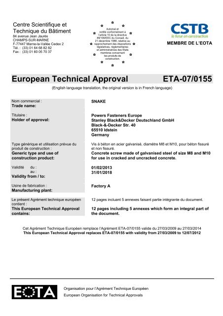
Centre Scientifique etTechnique du Bâtiment84 avenue Jean JaurèsCHAMPS-SUR-MARNEF-77447 Marne-la-Vallée Cedex 2Tél. : (33) 01 64 68 82 82Fax : (33) 01 60 05 70 37Autorisé etnotifié conformément àl’article 10 de la directive89/106/EEC du Conseil, du21 décembre 1988, relative aurapprochement des dispositionslégislatives, réglementaireset administratives des Etatsmembres concernantles produits deconstruction.MEMBRE DE L’EOTA<strong>European</strong> <strong>Technical</strong> <strong>Approval</strong>(English language translation, the original version is in French language)<strong>ETA</strong>-<strong>07</strong>/<strong>0155</strong>Nom commercial :Trade name:Titulaire :Holder of approval:Type générique et utilisation prévue duproduit de construction :Generic type and use ofconstruction product:Validité du :au :Validity from / to:Usine de fabrication :Manufacturing plant:Le présent Agrément technique européencontient :This <strong>European</strong> <strong>Technical</strong> <strong>Approval</strong>contains:SNAKEPowers Fasteners EuropeStanley Black&Decker Deutschland GmbHBlack-&-Decker Str. 4065510 IdsteinGermanyVis à béton en acier galvanisé, diamètre M8 et M10, pour béton fissuréet non fissuré.Concrete screw made of galvanised steel of size M8 and M10for use in cracked and uncracked concrete.01/02/201331/01/2018Factory A12 pages incluant 5 annexes faisant partie intégrante du document.12 pages including 5 annexes which form an integral part ofthe document.Cet Agrément Technique Européen remplace l’Agrément <strong>ETA</strong>-<strong>07</strong>/<strong>0155</strong> valide du 27/03/2009 au 27/03/2014This <strong>European</strong> <strong>Technical</strong> <strong>Approval</strong> replaces <strong>ETA</strong>-<strong>07</strong>/<strong>0155</strong> with validity from 27/03/2009 to 12/<strong>07</strong>/2012Organisation pour l’Agrément Technique Européen<strong>European</strong> Organisation for <strong>Technical</strong> <strong>Approval</strong>s
Page 2 of <strong>European</strong> <strong>Technical</strong> <strong>Approval</strong> <strong>ETA</strong> - <strong>07</strong>/<strong>0155</strong> issued 01 February 2013English translation prepared by CSTBILEGAL BASES AND GENERAL CONDITIONS1. This <strong>European</strong> <strong>Technical</strong> <strong>Approval</strong> is issued by the Centre Scientifique et Technique duBâtiment in accordance with: Council Directive 89/106/EEC of 21 December 1988 on the approximation of laws,regulations and administrative provisions of Member States relating to constructionproducts 1 , modified by the Council Directive 93/68/EEC of 22 July 1993 2 and Regulation (EC)N° 1882/2003 of the <strong>European</strong> Parliament and of the Council 3 ; Décret n° 92-647 du 8 juillet 1992 4construction;concernant l’aptitude à l’usage des produits de Common Procedural Rules for Requesting, Preparing and the Granting of <strong>European</strong><strong>Technical</strong> <strong>Approval</strong>s set out in the Annex of Commission Decision 94/23/EC 5 ; Guideline for <strong>European</strong> <strong>Technical</strong> <strong>Approval</strong> of « Metal Anchors for use in Concrete »<strong>ETA</strong>G 001, edition 1997 (Amended October 2005), Part 1 « Anchors in general », Part 3« Undercut anchors » and Common Understanding of Assessment Procedure CUAPn°06.01/20 dated October 2003.2. The Centre Scientifique et Technique du Bâtiment is authorised to check whether the provisionsof this <strong>European</strong> <strong>Technical</strong> <strong>Approval</strong> are met. Checking may take place in the manufacturingplant (for example concerning the fulfilment of assumptions made in this <strong>European</strong> <strong>Technical</strong><strong>Approval</strong> with regard to manufacturing). Nevertheless, the responsibility for the conformity of theproducts with the <strong>European</strong> <strong>Technical</strong> <strong>Approval</strong> and for their fitness for the intended useremains with the holder of the <strong>European</strong> <strong>Technical</strong> <strong>Approval</strong>.3. This <strong>European</strong> <strong>Technical</strong> <strong>Approval</strong> is not to be transferred to manufacturers or agents ofmanufacturer other than those indicated on page 1; or manufacturing plants other than thoseindicated on page 1 of this <strong>European</strong> <strong>Technical</strong> <strong>Approval</strong>.4. This <strong>European</strong> <strong>Technical</strong> <strong>Approval</strong> may be withdrawn by the Centre Scientifique et Techniquedu Bâtiment pursuant to Article 5 (1) of the Council Directive 89/106/EEC.5. Reproduction of this <strong>European</strong> <strong>Technical</strong> <strong>Approval</strong> including transmission by electronic meansshall be in full. However, partial reproduction can be made with the written consent of theCentre Scientifique et Technique du Bâtiment. In this case partial reproduction has to bedesignated as such. Texts and drawings of advertising brochures shall not contradict or misusethe <strong>European</strong> <strong>Technical</strong> <strong>Approval</strong>.6. The <strong>European</strong> <strong>Technical</strong> <strong>Approval</strong> is issued by the approval body in its official language. Thisversion corresponds to the version circulated within EOTA. Translations into other languageshave to be designated as such.12345Official Journal of the <strong>European</strong> Communities n° L 40, 11.2.1989, p. 12Official Journal of the <strong>European</strong> Communities n° L 220, 30.8.1993, p. 1Official Journal of the <strong>European</strong> Union n° L 284, 31.10.2003, p. 25Journal officiel de la République française du 14 juillet 1992Official Journal of the <strong>European</strong> Communities n° L 17, 20.1.1994, p. 34
Page 3 of <strong>European</strong> <strong>Technical</strong> <strong>Approval</strong> <strong>ETA</strong> - <strong>07</strong>/<strong>0155</strong> issued 01 February 2013English translation prepared by CSTBIISPECIFIC CONDITIONS OF THE EUROPEAN TECHNICAL APPROVAL1 Definition of product and intended use1.1. Definition of productThe Snake anchor is a screw manufactured from carbon steel and subsequently heat treated. Itis an internally threaded self tapping anchor, diameter M8 and M10 installed by drilling a pilothole with a standard ANSI bit (supplied with the Snake anchor) and screwed into the predrilledhole with a hex driver setting tool fitted on a impact screw driver. The special thread of theanchor cuts an internal thread into the member while setting. The anchorage is characterised bymechanical interlock in the special thread.For the installed anchor see Figure given in Annex 1.1.2. Intended useThe anchor is intended to be used for anchorages for which requirements for mechanicalresistance and stability and safety in use in the sense of the Essential Requirements 1 and 4 ofCouncil Directive 89/106/EEC shall be fulfilled and failure of anchorages made with theseproducts would compromise the stability of the works, cause risk to human life and/or lead toconsiderable economic consequences.The anchor is to be used only for anchorages subject to static or quasi-static loading inreinforced or unreinforced normal weight concrete of strength classes C 20/25 at minimum andC 50/60 at most according to EN 206-1: 2000-12. It may be anchored in cracked or uncrackedconcrete.The anchor may only be used in concrete subject to dry internal conditions.The connection of the fixture to the Snake anchor must be made with threaded elements ofgrade ≥ 4.8 only. The use of metric screws is not permittedThe provisions made in this <strong>European</strong> <strong>Technical</strong> <strong>Approval</strong> are based on an assumed intendedworking life of the anchor of 50 years. The indications given on the working life cannot beinterpreted as a guarantee given by the producer, but are to be regarded only as a means forchoosing the right products in relation to the expected economically reasonable working life ofthe works.2 Characteristics of product and methods of verification2.1. Characteristics of productThe Snake screw anchor corresponds to the drawings and provisions given in Annex 1. Thecharacteristic material values, dimensions and tolerances of the anchor not indicated in Annex 1shall correspond to the respective values laid down in the technical documentation 6 of this<strong>European</strong> <strong>Technical</strong> <strong>Approval</strong>.The characteristic anchor values for the design of anchorages are given in Annexes 3 and 4.6The technical documentation of this <strong>European</strong> <strong>Technical</strong> <strong>Approval</strong> is deposited at the Centre Scientifiqueet Technique du Bâtiment and, as far as relevant for the tasks of the approved bodies involved in theattestation of conformity procedure, is handed over to the approved bodies.
Page 4 of <strong>European</strong> <strong>Technical</strong> <strong>Approval</strong> <strong>ETA</strong> - <strong>07</strong>/<strong>0155</strong> issued 01 February 2013English translation prepared by CSTBThe product name, the nominal diameter of the anchor, the length of the anchor and the lengthof the internal threaded part are printed on the packaging unit according to Annex 5.The anchor shall only be packaged and supplied as a complete unit including drill bit and hexsetting tool.2.2. Methods of verificationThe assessment of fitness of the anchor for the intended use in relation to the requirements formechanical resistance and stability and safety in use in the sense of the EssentialRequirements 1 and 4 has been made in accordance with the « Guideline for <strong>European</strong><strong>Technical</strong> <strong>Approval</strong> of Metal Anchors for use in Concrete », Part 1 « Anchors in general » andPart 3 « Undercut anchors » on the basis of option 1.In addition to the specific clauses relating to dangerous substances contained in this <strong>European</strong>technical approval, there may be other requirements applicable to the products falling within itsscope (e.g. transposed <strong>European</strong> legislation and national laws, regulations and administrativeprovisions). In order to meet the provisions of the Construction Products Directive, theserequirements need also to be complied with, when and where they apply.3 Evaluation of Conformity and CE marking3.1. Attestation of conformity systemThe system of attestation of conformity 2 (i) (referred to as system 1) according to CouncilDirective 89/106/EEC Annex III laid down by the <strong>European</strong> Commission provides:a) tasks for the manufacturer:1. factory production control,2. further testing of samples taken at the factory by the manufacturer in accordancewith a prescribed test plan.b) tasks for the approved body:3. initial type-testing of the product,4. initial inspection of factory and of factory production control,5. continuous surveillance, assessment and approval of factory production control.3.2. Responsibilities3.2.1. Tasks of the manufacturer3.2.1.1.Factory production controlThe manufacturer has a factory production control system in the plant and exercises permanentinternal control of production. All the elements, requirements and provisions adopted by themanufacturer are documented in a systematic manner in the form of written policies andprocedures. This production control system ensures that the product is in conformity with the<strong>European</strong> <strong>Technical</strong> <strong>Approval</strong>.The manufacturer shall only use raw materials supplied with the relevant inspection documentsas laid down in the prescribed test plan 7 . The incoming raw materials shall be subject tocontrols and tests by the manufacturer before acceptance. Check of incoming materials shallinclude control of the inspection documents presented by suppliers (comparison with nominalvalues) by verifying dimension and determining material properties.The frequency of controls and tests conducted during production and on the assembled anchoris laid down in the prescribed test plan taking account of the automated manufacturing processof the anchor.7The prescribed test plan has been deposited at the Centre Scientifique et Technique du Bâtiment and isonly made available to the approved bodies involved in the conformity attestation procedure.
Page 5 of <strong>European</strong> <strong>Technical</strong> <strong>Approval</strong> <strong>ETA</strong> - <strong>07</strong>/<strong>0155</strong> issued 01 February 2013English translation prepared by CSTBThe results of factory production control are recorded and evaluated.The records shall be presented to the inspection body during the continuous surveillance. Onrequest, they shall be presented to the Centre Scientifique et Technique du Bâtiment.Details of the extent, nature and frequency of testing and controls to be performed within thefactory production control shall correspond to the prescribed test plan which is part of thetechnical documentation of this <strong>European</strong> <strong>Technical</strong> <strong>Approval</strong>.3.2.1. 2.Other tasks of the manufacturerThe manufacturer shall, on the basis of a contract, involve a body which is approved for thetasks referred to in section 3.1 in the field of in order to undertake the actions laid down insection 3.2.2. For this purpose, the control plan referred to in sections 3.2.1 and 3.2.2 shall behanded over by the manufacturer to the approved body involved. The manufacturer shall makea declaration of conformity, stating that the construction product is in conformity with theprovisions of this <strong>European</strong> technical approval.3.2.2. Tasks of approved bodies3.2.2.1. Initial type-testing of the productFor initial type-testing the results of the tests performed as part of the assessment for the<strong>European</strong> <strong>Technical</strong> <strong>Approval</strong> shall be used unless there are changes in the production line orplant. In such cases the necessary initial type-testing has to be agreed between the CentreScientifique et Technique du Bâtiment and the approved bodies involved.3.2.2.2. Initial inspection of factory and of factory production controlThe approved body shall ascertain that, in accordance with the prescribed test plan, the factoryand the factory production control are suitable to ensure continuous and orderly manufacturingof the anchor according to the specifications mentioned in 2.1. as well as to the Annexes to the<strong>European</strong> <strong>Technical</strong> <strong>Approval</strong>.The approved certification body involved by the manufacturer shall issue an EC certificate ofconformity of the product stating the conformity with the provisions of this <strong>European</strong> technicalapproval.3.2.2.3. Continuous surveillanceThe approved certification body involved by the manufacturer shall visit the factory at least oncea year for regular inspection. It has to be verified that the system of factory production controland the specified automated manufacturing process are maintained taking account of theprescribed test plan.Continuous surveillance and assessment of factory production control have to be performedaccording to the prescribed test plan.The results of product certification and continuous surveillance shall be made available ondemand by the certification body or inspection body, respectively, to the Centre Scientifique etTechnique du Bâtiment. In cases where the provisions of the <strong>European</strong> <strong>Technical</strong> <strong>Approval</strong> andthe prescribed test plan are no longer fulfilled the conformity certificate shall be withdrawn andCSTB informed without delay.3.3. CE-Marking
Page 6 of <strong>European</strong> <strong>Technical</strong> <strong>Approval</strong> <strong>ETA</strong> - <strong>07</strong>/<strong>0155</strong> issued 01 February 2013English translation prepared by CSTBThe CE marking shall be affixed on each packaging of anchors. The symbol « CE » shall beaccompanied by the following information: Commercial name; Name or identifying mark of the producer and manufacturing plant; Name of approval body and <strong>ETA</strong> number; Identification number of the certification body; Number of the EC certificate of conformity; Use category (<strong>ETA</strong>G 001-3 Option 1); The last two digits of the year in which the CE-marking was affixed; Size.4 Assumptions under which the fitness of the product for the intended use wasfavourably assessed4.1. ManufacturingThe anchor is manufactured in accordance with the provisions of the <strong>European</strong> <strong>Technical</strong><strong>Approval</strong> using the automated manufacturing process as identified during inspection of the plantby the approved body and laid down in the technical documentation.The <strong>European</strong> <strong>Technical</strong> <strong>Approval</strong> is issued for the product on the basis of agreeddata/information, deposited with Centre Scientifique et Technique du Bâtiment, which identifiesthe product that has been assessed and judged. Changes to the product or production process,which could result in this deposited data/information being incorrect, should be notified toCentre Scientifique et Technique du Bâtiment before changes are introduced. CentreScientifique et Technique du Bâtiment will decide whether or not such changes affect the <strong>ETA</strong>and consequently the validity of the CE marking on the basis of the <strong>ETA</strong> and if so whetherfurther assessment or alterations to the <strong>ETA</strong> shall be necessary.4.2. Installation4.2.1. Design of anchoragesThe fitness of the anchors for the intended use is given under the following conditions:The anchorages are designed in accordance with the « Guideline for <strong>European</strong> <strong>Technical</strong><strong>Approval</strong> of Metal Anchors for Use in Concrete », Annex C, Method A, under the responsibilityof an engineer experienced in anchorages and concrete work.Verifiable calculation notes and drawings are prepared taking account of the loads to beanchored.The position of the anchor is indicated on the design drawings (e.g. position of the anchorrelative to reinforcement or to support, etc.).4.2.2. Installation of anchorsThe fitness for use of the anchor can only be assumed if the anchor is installed as follows: anchor installation carried out by appropriately qualified personnel and under the supervisionof the person responsible for technical matters on the site; use of the anchor only as supplied by the manufacturer without exchanging the componentsof an anchor. The holes must be drilled with the drill bit supplied in the Snake’s package only; anchor installation in accordance with the manufacturer’s specifications and drawingsprepared for that purpose and using the appropriate special tools;
Page 7 of <strong>European</strong> <strong>Technical</strong> <strong>Approval</strong> <strong>ETA</strong> - <strong>07</strong>/<strong>0155</strong> issued 01 February 2013English translation prepared by CSTB checks before placing the anchor to ensure that the strength class of the concrete in whichthe anchor is to be placed is in the range given and is not lower than that of the concrete towhich the characteristic loads apply; check of concrete being well compacted, e.g. without significant voids; clearing the hole of drilling dust; anchor installation ensuring the specified embedment depth; this is ensured if the hex settingtool is used for installation of the anchor and the flange of the setting tool rest on theconcrete surface after the installation keeping of the edge distance and spacing to the specified values without minus tolerances; positioning of the drill holes without damaging the reinforcement; in case of aborted hole: new drilling at a minimum distance away of twice the depth of theaborted hole or smaller distance if the aborted drill hole is filled with high strength mortar andif under shear or oblique tension load it is not to the anchor in the direction of loadapplication; Only threaded parts of grade ≥ 4.8 are permitted application of the torque moment not exceeding the value given in Annex 2 and using acalibrated torque wrench. For the size M8: check that the thread engagement is full anchor depth; the use ofmetric screws is not permitted.4.2.3. Responsibility of the manufacturerIt is the manufacturer’s responsibility to ensure that the information on the specific conditionsaccording to 1 and 2 including Annexes referred to as well as in sections 4.2.1. and 4.2.2. isgiven to those who are concerned. This information may be made by reproduction of therespective parts of the <strong>European</strong> <strong>Technical</strong> <strong>Approval</strong>. In addition all installation data shall beshown clearly on the package and/or on an enclosed instruction sheet, preferably usingillustration(s).The minimum data required are: drill bit diameter, thread diameter, minimum installation depth, minimum hole depth, information on the installation procedure, including cleaning of the hole, preferably by meansof an illustration, reference to any special installation equipment needed, identification of the manufacturing batch.All data shall be presented in a clear and explicit form.The original French version issigned byLe Directeur TechniqueC. BALOCHE
Page 8 of <strong>European</strong> <strong>Technical</strong> <strong>Approval</strong> <strong>ETA</strong> - <strong>07</strong>/<strong>0155</strong> dated 01 February 2013English translation prepared by CSTBTable 1: Dimensions and material of SnakeLength of the anchor D [mm] 31Diameter of the shaft G [mm] 12.7Diameter of the thread F [mm] 14.7Length of the internal threadedpartMaterialC [mm] 18Steel C10B21SMarking of the anchor with the letter “S” at thebottom end of the Snake concrete screw.Intended use:Use in cracked or non-cracked concrete in dry internal conditionsFor the threaded parts only steel grade ≥ 4.8 is permittedSNAKE Concrete Screw anchorProduct, Dimensions and materialAnnex 1of <strong>European</strong> <strong>Technical</strong><strong>Approval</strong><strong>ETA</strong>-<strong>07</strong>/<strong>0155</strong>
Page 9 of <strong>European</strong> <strong>Technical</strong> <strong>Approval</strong> <strong>ETA</strong> - <strong>07</strong>/<strong>0155</strong> dated 01 February 2013English translation prepared by CSTBheftfixd0MhshthnomhholehImportant notice for the size M8:Check that the thread engagement is full anchor depth. The use of metric screws is notpermitted.Table 2: Installation parametersInner diameter of the thread M [mm] M8 M10Nominal drill bit diameter d 0 [mm] 12.7 1Cutting diameter of the drill bitd cut ≥ [mm] 12.95d cut ≤ [mm] 13.46Depth of the drill hole h 1 ≥ [mm] 50Embedment depth of the anchor h nom ≥ [mm] 41Maximum torque moment T max ≤ [N.m] 10Note 1: This is a ½ inch ANSI drill bit supplied in the same packaging than the Snake anchors.Table 3: Minimum thickness of concrete, minimum spacing and edge distancesMinimum thickness of concretehmembermin [mm] 100Minimum spacing s min [mm] 80SNAKE Concrete Screw anchorInstallation parametersAnnex 2of <strong>European</strong> <strong>Technical</strong><strong>Approval</strong><strong>ETA</strong>-<strong>07</strong>/<strong>0155</strong>
Page 10 of <strong>European</strong> <strong>Technical</strong> <strong>Approval</strong> <strong>ETA</strong> - <strong>07</strong>/<strong>0155</strong> dated 01 February 2013English translation prepared by CSTBTable 5: Design method ACharacteristic values for tension loadSteel failure M8 M10Characteristic resistance N Rk,s kN 15.4 24.4Partial safety factor Ms - 1.48Pull out failureCharacteristic resistance inuncracked concreteCharacteristic resistance in crackedconcreteIncreasing factor for theCharacteristic resistance in crackedand uncracked concreteN Rk,p C20/25 kN 5.0N Rk,p C20/25 kN 3.0 c C25/30 - 1.10 c C30/37 - 1.22 c C35/45 - 1.34 c C40/50 - 1.41 c C45/55 - 1.48 c C50/60 - 1.55Partial safety factor Mp - 1.80Concrete cone failure / SplittingEmbedment depth for the design h ef mm 28 2SpacingEdge distances cr,N mm 84s cr,sp mm 160c cr,N mm 42c cr,sp mm 80Partial safety factor Mc Msp - 1.80Table 6: Displacements under tension loadsUncracked concreteM8 or M10Tension load N kN 2.4DisplacementCracked concrete N0 mm 0.1 N∞ mm 0.7Tension load N kN 1.4Displacement N0 mm 0.4 N∞ mm 0.7Note 2: The embedment depth h ef for the design is calculated as h ef = 0.85 . (h nom - 0.5 . h t - h s ).This embedment depth for the design is calculated in order that the characteristic loads fit with the designmodel of the <strong>ETA</strong>G 001 Annex C.The embedment depth h ef for the design must not be mixed up with the setting depth h nom which is theactual depth of the anchor. In the case of the Snake anchor, h nom = 41mm.SNAKE Concrete Screw anchorDesign method ACharacteristic values for tension loads,DisplacementsAnnex 3of <strong>European</strong> <strong>Technical</strong><strong>Approval</strong><strong>ETA</strong>-<strong>07</strong>/<strong>0155</strong>
Page 11 of <strong>European</strong> <strong>Technical</strong> <strong>Approval</strong> <strong>ETA</strong> - <strong>07</strong>/<strong>0155</strong> dated 01 February 2013English translation prepared by CSTBTable 7: Design method ACharacteristic values for shear loadSteel failure without lever arm M8 M10Characteristic resistance V Rk,s kN 7.7 3 12.2 3Partial safety factor MS - 1.50Steel failure with lever arm Characteristic resistance M 0 Rk,s N.m 16.0 31.0Partial safety factor MS - 1.50Pry out failure Factor k in <strong>ETA</strong>G 001 Annex C equation5.6k - 1.0Partial safety factor Mpr - 1.50Concrete edge failure Effective length of anchor l f mm 31.8Diameter of anchor d nom mm 12.7Partial safety factor MC - 1.50Note 3: Pry out failure mode is predominantSteel failure with lever arm has to be considered in order to take account of the distance from the upper partof the anchor and the concrete surface.Table 8: Displacements under shear loadsCracked concrete and UncrackedconcreteM8 or M10Shear load V kN 2.4Displacement V0 mm 1.0 v∞ mm 1.5SNAKE Concrete Screw anchorDesign method ACharacteristic values for shear loads,DisplacementsAnnex 4of <strong>European</strong> <strong>Technical</strong><strong>Approval</strong><strong>ETA</strong>-<strong>07</strong>/<strong>0155</strong>
Page 12 of <strong>European</strong> <strong>Technical</strong> <strong>Approval</strong> <strong>ETA</strong> - <strong>07</strong>/<strong>0155</strong> dated 01 February 2013English translation prepared by CSTBInstructions For Use:Using the properdrill bit size, drill ahole into the basematerial to therequired depth. Thetolerances of thecarbide drill bitused should meetthe requirement ofANSI StandardB212.15 (seeAnnex 2 table 2).Blow the holeclean.Labels printed on the packaging:Select a poweredimpact wrench thatdoes not exceedthe maximumtorque (see Annex2 table 4), for theselected anchordiameter. Attachthe snake+ settingtool supplied byPowers Fastenersto the impactwrench. Mount theanchor onto thesetting tool.Drive the anchorinto the hole untilthe shoulder ofthe Snake +setting tool comesinto contact withthe surface of thebase material. Donot spin thesetting tool off theanchor todisengage.Insert the rod into theSnake, taking care notto exceed the maximumspecified tighteningtorque of the steel insertelement, T max .For Snake M8 minimumthread engagementmust be full anchordepth and the use ofmetric screws is notpermitted.For Snake M10minimum threadengagement should beat least 10mm.SNAKE Concrete Screw anchorInstructions For UseAnnex 5of <strong>European</strong> <strong>Technical</strong><strong>Approval</strong><strong>ETA</strong>-<strong>07</strong>/<strong>0155</strong>