AN-100 _HF Multicoupler_3101 - JANADA
AN-100 _HF Multicoupler_3101 - JANADA
AN-100 _HF Multicoupler_3101 - JANADA
- No tags were found...

You also want an ePaper? Increase the reach of your titles
YUMPU automatically turns print PDFs into web optimized ePapers that Google loves.
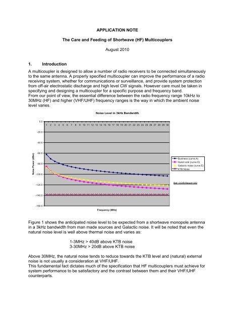
APPLICATION NOTEThe Care and Feeding of Shortwave (<strong>HF</strong>) <strong>Multicoupler</strong>sAugust 20101. IntroductionA multicoupler is designed to allow a number of radio receivers to be connected simultaneouslyto the same antenna. A properly specified multicoupler can improve the performance of a radioreceiving system, whether for communications or surveillance, and provide system protectionfrom off-air electrostatic discharge and high level CW signals. However care must be taken inspecifying and designing a multicoupler for a specific purpose and frequency band.From our point of view, the essential difference between the radio frequency range 10kHz to30MHz (<strong>HF</strong>) and higher (V<strong>HF</strong>/U<strong>HF</strong>) frequency ranges is the way in which the ambient noiselevel varies.Noise Level in 3kHz Bandwidth0.01 2 3 4 5 6 7 8 9 10 11 12 13 14 15 16 17 18 19 20 21 22 23 24 25 26 27 28 29 30-20.0-40.0Noise Power (dBm)-60.0-80.0-<strong>100</strong>.0Business (curve A)Quiet rural (curve D)Galactic noise (curve E)KTB Noise-120.0Ref: CCIR Report 322-140.0-160.0Frequency (MHz)Figure 1 shows the anticipated noise level to be expected from a shortwave monopole antennain a 3kHz bandwidth from man made sources and Galactic noise. It will be noted that even thenatural noise level is well above thermal noise and varies as:1-3MHz > 40dB above KTB noise3-30MHz > 20dB above KTB noiseAbove 30MHz, the natural noise tends to reduce towards the KTB level and (natural) externalnoise is not usually a consideration at V<strong>HF</strong>/U<strong>HF</strong>.This fundamental fact dictates much of the specification that <strong>HF</strong> multicouplers must achieve forsystem performance to be satisfactory and the contrast between them and their V<strong>HF</strong>/U<strong>HF</strong>counterparts.
(F1+/-F2) and (2F1+/-F2) etc. The square and cube terms of a number less than 1 areconsidered vanishingly small.The 2-3OMHz band covers four octaves of frequency so there is plenty of room for both the 3 rdorder (2F1 +/-F2) and the 2 nd order (F1+F2) intermodulation products to appear to look like realsignals, when the system open to the full band. The front-end multicoupler and/or pre-amplifierare indeed wideband in most cases. The first band limiting element in the radio system isusually the front-end pre-selector in the receiver, which is after the multicoupler.So, intermodulation in the multicoupler will always affect the system adversely.To quantify the intermodulation effect, we need to look at the levels of spurious actuallygenerated.<strong>100</strong>SHORTWAVE (<strong>HF</strong>) MULTICOUPLERTR<strong>AN</strong>SFER CHARACTERISTIC802nd Order Intercept Point (80dBm)60403rd Order Intercept Point (40dBm)Output Power Level200-20-40Output Level2nd Order Spurious3rd Order Spurious-60SFDR (2nd Order)- 90dBm-80-<strong>100</strong>SFDR (3rd Order) -95dBmEnvironmental Noise level (-<strong>100</strong>dBm)-120-140kTB Noise level (-139dBm)-<strong>100</strong> -80 -60 -40 -20 0 +20 +40 +60 +80Input Power Level (dBm)The diagram illustrated the relationship between the 2 nd and 3 rd Order Output Intercept Points(OPIP) and the intermodulation spurious produced relative to the fundamental output of the
device. The non-linear characteristic produces 2 nd order (F1+/-F2) and 3 rd order (2F1+/-F2)spurious signals in accordance with the rules illustrated above.Thus, the ideal multicoupler has zero gain and the highest possible OPIPs points which will inturn yield the highest 2 nd and 3 rd Order spurious free dynamic range.2.1.2 Spurious Free Dynamic RangeThe spurious free dynamic range (SFDR) is important because it sets the highest signal whichcan pass through the device without developing a spurious signal of greater amplitude than thenoise floor of the system. So, a system designed to identify and monitor low level signals off-air,in the presence of higher in-band signals (broadcasts and friendly communication signals) canoperate without generating intermodulation spurious with interfering signals up to a level set byHighest Signal (dBm) = Noise floor (dBm) + SFDR (dB).Note that the level of the noise floor in the <strong>HF</strong> band is set by the ambient (environmental) noiseand not by the system itself. The noise figure of the system is usually quoted for a 3kHzbandwidth, which sets the thermal (kTB) noise at -139dBm. The noise generated by the systemis given byNoise generated = kTB*(F-1)*GWherek= Boltzmanns ConstantT = absolute temperatureB = bandwidth (3kHz)F= noise figure (as a factor)G = gain of the system (as a factor)If the feeder system (including the multicoupler) produces noise less than the ambient noise,then the feeder system will have no influence on the minimum discernible signal, which willusually be some 3dB above the ambient noise. A typical multicoupler noise figure is 7dB, whichleaves the output noise floor at -132dBm, a full 30dB plus below the usual level ofenvironmental noise.2.1.3 Techniques to Minimise IntermodulationThe solution to this intermodulation problem is either:• Prevent the formation of the spurious signal at source through linear amplification or• Cancel the spurious using signal of equal frequency and power in anti-phase.Older systems used amplifiers with high power output capability in the hope that such amplifierswould be very linear when used at low levels of power. This is the same approach as HiFi buffsand it works – to an extent. The penalty paid was the high power consumed in class 'A'amplifiers, higher operating temperatures, which leads to lower component reliability andcomponent aging. In large systems, fuel costs are also a consideration.The modern way is to use negative feedback and positive feed-forward to achieve high linearitywith relatively low power amplifiers. This has the advantage of lower prime power, which iseasier on the fuel bill and reduces waste heat, which makes for higher reliability of components.
The most spectacular results are obtained with the feed forward technique, which was reintroducedinto this application by Raven Research some time ago. In this application, we usesuch techniques for a minimum divide ratio of 32:1 (32-way coupler). The amplifier has a gainof 18dB and 2 nd /3 rd IP of 120/60 dBm respectively for a power consumption of 20W. The feedforward technique also improves the noise figure which is typically 5dB for this amplifier.1.3 IsolationIn shortwave multicouplers, Raven Research uses 'lossless' power dividers. These are ferritecore transformers designed to divide the power with minimum signal loss, typically a few tenthsof a dB more than the divider loss (3dB). These designs have inherently higher port-to-portisolation than resistive dividers when properly terminated.The Output-to-Output isolation is important in preventing local oscillator spurious emanatingfrom the receiver feeder passing to the input port of the adjacent receiver and appearing as anew signal.Reverse isolation (Output-to-Input) is important lest any LO or other spurious signal emanatingfrom one of the receivers passes to the antenna feeder and transmits to an astute and capableadversary.1.4 GainThe gain of the unit needs only be set to reduce the effect of the cascade and preserve thereceiver noise figure for the system (that is, not make it worse).Modern surveillance receivers boast a noise figure of 11dB with pre-amplifier but only 20dBwithout the amplifier. As we shall see below, unless the pre-amplifier has a high spurious freedynamic range or a narrowband pre-selector, the system might be better off without it.Nevertheless, using the classic formula,F tot = F 1 + F 2 -1/G 1Where F 1 = Noise figure of first stage = 7dB = (factor) 5F 2 = Noise figure of second stage = 11dB = (factor) 12.59G 1 = Gain of first stage = 2dB = (factor) 1.6F tot = Noise figure of overall systemOverall Noise Figure = 5 + (12.59-1)/1.6 = 10.9dB1.5 Front end ProtectionShortwave front-ends are quite vulnerable to electro-static discharge because most of theenergy in a lightning strike exists in the <strong>HF</strong> band and below. They are also prone to damage byhigh power transmissions, particularly from high power mobile transmitters parked near thesystem antenna, which will typically have a high effective aperture.Raven shortwave multicouplers are usually protected with a gas discharge tube (90V flashover) and a diode chain. This circuit will protect the front-end circuit from +40dBm CW and50kV pulse with 1uS rise time and 50uS duration.The RR1110 series has an additional protection circuit which will actually shut down the preamplifierand reduce the gain, once the input power exceeds +15dBm. This additional feature is
intended to protect the following receiver front-end, wherever the system is exposed to highpower in-band transmissions.1.6 BITEThe RR1110 series is very much intended as a system product, to be integrated into areceiving system. With this in mind, built-in-test-equipment (BITE) circuits are included in thedesign. These circuits monitor the performance of the bias on the two elements of the push-pullamplifiers which are at the heart of the design. If these currents go out of balance by more thanthe permitted amount, the operation of the multicoupler is not immediately compromised. Theunit will usually fail gracefully over a period of time.However, the BITE circuit is immediately triggered and the external alarm is activated.This gives the operator immediate warning of an impending failure and information on thelocation of the endangered unit.1.7 MechanicalThe RR1110 series of multicouplers is housed in 19" rack mounting units, 1U high (4,8,16-way)and 2U high (32-way)Other mechanical arrangements can be provided to order save space or provide for alternativemounting and/or housing arrangements. The RR1115 series, for example, provides up to 16multicoupler modules in a single 19" rack mounting unit, with 4, 8 or 16 outputs per module.This arrangement is sometimes convenient very large distribution systems, where space is at apremium.1.8 Power SuppliesThe RR1110 series of 19" rack mounting units are usually powered from the mains supply andoperate from 90-240 Vac (50-60Hz) and using switch mode converters. These supplies haveproved highly reliable (>250,000 hours MTBF) but alternative linear DC supplies (24Vdc) withredundancy are available for systems where no-break operation is mandatory.1.9 Heat Dissipation and Thermal ManagementThe amplifier is the main (only) heat generating component in the system and the supply isgenerally set to 800mA at 24Vdc (20W). The heat is conducted away through a substantial heatsink plate to the case providing a low thermal resistance from the heat source to the case.The waste heat must be dissipated through the case to the circulating air in the rack.Typically the difference between case temperature and surrounding air must be maintainedgreater than 5 degrees C.The physical orientation of the unit is optimised for heat transfer but best practice is to limit thenumber of 19" 1U high units to five stacked with a 1U air gap both above and below.4. Environmental ConsiderationsThe RR1110 multicoupler contains no toxic materials except for a small quantity of berylliumoxide in the main transistors. Insulation is specified for low smoke and fumes.
The unit is CE marked and meets all the provisions of European Health and Safety regulationsat current date.Disposal at end of life or surplus to requirements should be in accordance with the localregulations on electrical waste (WEE Directive within EU) or the units can be returned to RavenResearch for disposal for an additional cost, to be agreed before returning the unit(s).5. Packaging - Size and weights, shipping weightsQty Article Weight PackedDeadweightVolumetricWeight1 2.8kg 4kg 5.6kg4 11.2kg 14kg 17kg