PLC LEVEL CONTROLLER - Home | Kimray Mobile
PLC LEVEL CONTROLLER - Home | Kimray Mobile
PLC LEVEL CONTROLLER - Home | Kimray Mobile
- No tags were found...

You also want an ePaper? Increase the reach of your titles
YUMPU automatically turns print PDFs into web optimized ePapers that Google loves.
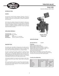
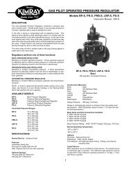
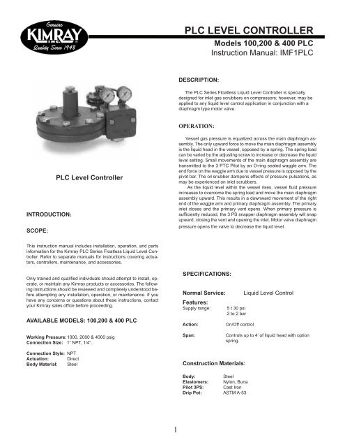
<strong>PLC</strong> <strong>LEVEL</strong> <strong>CONTROLLER</strong>Models 100,200 & 400 <strong>PLC</strong>Instruction Manual: IMF1<strong>PLC</strong>DESCRIPTION:The <strong>PLC</strong> Series Floatless Liquid Level Controller is speciallydesigned for inlet gas scrubbers on compressors; however, may beapplied to any liquid level control application in conjunction with adiaphragm type motor valve.OPERATION:INTRODUCTION:SCOPE:<strong>PLC</strong> Level ControllerVessel gas pressure is equalized across the main diaphragm assembly.The only upward force to move the main diaphragm assemblyis the liquid head in the vessel, opposed by a spring. The spring loadcan be varied by the adjusting screw to increase or decrease the liquidlevel setting. Small movements of the main diaphragm assembly aretransmitted to the 3 PTC Pilot by an O-ring sealed waggle arm. Theend force on the waggle arm due to vessel pressure is opposed by thepivot bar. The oil snubber dampens effects of pressure pulsations, asmay be experienced on inlet scrubbers.As the liquid level within the vessel rises, vessel fluid pressureincreases to overcome the spring load and move the main diaphragmassembly upward. This results in a downward movement of the rightend of the waggle arm and primary diaphragm assembly. The primaryinlet closes and the primary vent opens. When primary pressure issufficiently reduced, the 3 PS snapper diaphragm assembly will snapupward, closing the vent and opening the inlet. Motor valve diaphragmpressure opens the valve to decrease the liquid level.This instruction manual includes installation, operation, and partsinformation for the <strong>Kimray</strong> <strong>PLC</strong> Series Floatless Liquid Level Controller.Refer to separate manuals for instructions covering actuators,controllers, maintenance, and accessories.Only trained and qualified individuals should attempt to install, operate,or maintain any <strong>Kimray</strong> products or accessories. The followinginstructions should be reviewed and completely understood beforeattempting any installation, operation, or maintenance. If youhave any concerns or questions about these instructions, contactyour <strong>Kimray</strong> sales office before proceeding.AVAILABLE MODELS: 100,200 & 400 <strong>PLC</strong>SPECIFICATIONS:Normal Service:Features:Supply range:Action:5 t 30 psi.3 to 2 barOn/Off controlLiquid Level ControlWorking Pressure: 1000, 2000 & 4000 psigConnection Size: 1” NPT, 1/4”.Span:Controls up to 4’ of liquid head with optionspring.Connection Style: NPTActuation: DirectBody Material: SteelConstruction Materials:Body:SteelElastomers: Nylon, BunaPilot 3PS: Cast IronDrip Pot: ASTM A-531
<strong>PLC</strong> <strong>LEVEL</strong> <strong>CONTROLLER</strong>Models 100,200 & 400 <strong>PLC</strong>Instruction Manual: IMF1<strong>PLC</strong>2
<strong>PLC</strong> <strong>LEVEL</strong> <strong>CONTROLLER</strong>Models 100,200 & 400 <strong>PLC</strong>Instruction Manual: IMF1<strong>PLC</strong>INSTALLATION CONT:BEFORE INSTALLATION:Be sure you fully understand the application, operation, and connectionof the device before installing.WARNING:Only trained personnel should install or service a control valve orcontrol device. Control valves and other control devices shouldbe installed, operated, and maintained in accordance with internationalcodes and regulations, manufacturer’s instructions, andproven best practices.Personal injury, equipment damage, property damage, leakage, orbursting of pressure-containing parts may result if the controlleris overpressured or installed where service conditions could exceedthe limits given in the SPECIFICATIONS section.Overpressure protection should also be provided if the valve inletpressure may exceed the safe working pressure of the equipmentdownstream.To avoid injury or damage, install pressure-relieving or pressurelimiting devices to prevent service conditions from exceedingthose limits. Consult the appropriate code, regulations, or standards.Consideration should be given to the potential risk of injury orproperty damage due to escaping fluid. To avoid such risks, installthe controller in a safe location.ADJUSTMENT:The <strong>PLC</strong> liquid pilot has one adjustment for controlling liquid level ina vessel. In order to increase liquid level in vessel tighten adjustmentknob on top of pilot. This will compress spring on top of diaphragmcausing more diaphragm resistance to liquid head level. To decreaseliquid level in vessel simply loosen adjustment knob.START-UP AND TEST:Warning:Before performing any service be sure that the regulator is fully isolatedand that all pressure upstream and downstream has been relieved.Use bypass valves or fully shut off the process.Be sure that any operating or instrument gas lines have been disconnected.Never assume that a check valve is fully blocking the downstream line.Never tighten any fitting or the main connections to the regulator whilethere is pressure on the line.NOTE:When a gasket seal is disturbed during disassembly a new gasketshould be installed during reassembly to ensure proper sealing.MAINTENANCE:Maintenance should be performed on a regular basis. An initial inspectioninterval of 12 months is recommended. Depending on the serviceconditions and the condition of the valve, the inspection interval may bedecreased or increased.Warning: If the pilot vents fluid or a leak develops inthe system, it indicates that service is required. Failureto take the pilot out of service immediately maycreate a hazardous condition.Repair kits are available. Consult the <strong>Kimray</strong> Catalog, Section F, or thepacking slip which is enclosed with each pilot for the correct Repair Kitnumber.REPAIR HINTS:* If pilot bleeds gas continuously, the pilot plug seat may be dirty.* Diaphragms will harden with age.* Pressure differential above 20 psi across main diaphragm couldcause it to rupture.With installation completed and appropriate relief and check valvesinstalled and set, slowly open the upstream and downstream shutoffvalves. In order to verify liquid level a sight glass will need to be installed.Make sure supply gas is turned on to pilot.1. Start with adjustment screw half way turned in. this will be approximately6” above <strong>PLC</strong> pilot.2. Verify that liquid dump valve opens when liquid level in tank is above<strong>PLC</strong> pilot.3. Once operation of liquid dump valve is verified, use adjustment screwand sight glass to set liquid level in vessel.3
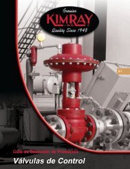
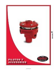
<strong>PLC</strong> <strong>LEVEL</strong> <strong>CONTROLLER</strong>Models 100,200 & 400 <strong>PLC</strong>Instruction Manual: IMF1<strong>PLC</strong>This is a general representation of a <strong>PLC</strong> Pilot. For specific parts and their orientation refer to the <strong>Kimray</strong> Catalog or the packing slip which is enclosedwith each regulator.Key Description Key Description Key Description1. Elbow 20. Spring Plate 39. Case2. Nut 21. Spacer Place 40. Pilot Housing3. Tubing 22. Upper Flange 41. Pilot Plug4. Nipple 23. Gasket 42. Seat5. 3 PS Snapper Pilot 24. O-Ring 43. Pilot Cap6. Elbow 25. Diaphragm 44. Screw7. Elbow 26. Plug 45. Screw8. Tubing 27. Diaphragm Plate 46. Cover9. Nipple 28. Diaphragm Seat Ring 47. Gasket10. Flange Assembly 29. Diaphragm Bolt 48. Screw11. Stem 30. Knob 49. Spacers12. Body 31. Housing 50. Screw13. Drip Pot 32. Spring 51. Snubber Assembly14. Connector 33. Nut 52. Silicone Oil15. Nut 34. O-Ring 53. Seat Assembly16. Set Screw 35. O-Ring 54. Pivot Bar17. Screw 36. Screw 55. Waggle Arm18. Back-Up 37. Packing Gland Assembly 56. O-Ring19. O-Ring 38. Gauge 57. Lower Flange4