An Inverted Vee Engine - WWII Aircraft Performance
An Inverted Vee Engine - WWII Aircraft Performance
An Inverted Vee Engine - WWII Aircraft Performance
- No tags were found...

Create successful ePaper yourself
Turn your PDF publications into a flip-book with our unique Google optimized e-Paper software.
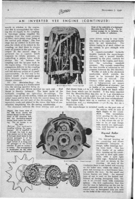
NOVEMBER 7, 1940A N I N V E R T E D V E E E N G I N E ( C O N T I N U E Dspeeds in relation to the engine,and this is accomplished by reducingthe oil supply to the coupling.A two-stage pump supplies thecoupling from the main pressureoil filter, each pump stage being ofthe normal gear design. The firststage has no control on it and suppliesthe whole of its output to thecoupling, so that there is alwayssome oil present in the spaces. Theoutput of the second stage isgoverned by a capsule whichresponds to intake pressure, socontrolling a piston valve whichdivides the oil between thecoupling and the by-pass back tothe engine sump. The second stagecommences delivery to the couplingat a barometric height of 4,900ft.,and full delivery occurs at 11,500ft.approximately. In this way is thedesired result of a variable-speeddrive between engine and superchargerobtained.On the Mercedes-Benz thehydraulic coupling is a double-sidedone, the driving member being onthe inside with one driven member on each end. Endthrust is thereby balanced. The inner parts of thehydraulic coupling are light-alloy die-castings. Theannular rings of curved section, which are attached to thetadial vanes and so help to form the correct shape for thefluid channels, are not part of the die-casting. They areseparately made and pinned to the vanes, this form of constructionsimplifying the die-casting considerably.The clearance between the inner driving unit and the(Right) The front view ofthe DB 601A shows thesplined flange for the attachmentof the airscrew hub,and the horseshoe-shapedheader tank under the cowling.The air intake is onthe right.(Below) The hydrauliccoupling driving the supercharger.Oil is supplied toit through the hole A andthen passes out of the shaftB through small holes to thecurved passages C of thedriving member. By centrifugalaction it is flung intothe passages of the drivenmember D and so causes itto rotate. The arrangementis duplicated on the otherend, so balancing end thrust.M.A .P. Official Pholo. Crown Copyright.M .A .P.Official Photo.Crown -CopyrightView of the underside of a damagedMercedes-Benz DB 601A. The injectionpumps lie in between thetwo banks of cylinders.outer driven casing is very close.The slots on the inner unit probablyserve to aid lubrication. Thedriven casing is of steel, ribbed onthe outside to give strength withlightness.A capsule-controlled butterflythrottle controls the superchargerdelivery, and a second throttle,operated by the pilot, controls theair supply to the engine, and thereforethe induction manifoldpressure. The capsule controllingthe first throttle is subjected to thepressure between the two throttles.Worthy of note is the clockworkmechanism which permits theboost to be increased for oneminute only at take-off. TheGerman boost gauge is marked,not in kilogrammes per squaremm. or millimetres of mercury, butin tenths of an atmosphere. Thedial shows from 0.6 to 1.8, which limits are much widerthan those which can be reached. It has been reportedthat the Mercedes-Benz has run up to 1.45 atmospheres( + 6.3 lb./sq. in.) and 2,500 r.p.m. for take-off, but thisseems very high and the claim has not been substantiated.The highest figure seen on a machine by Air Ministrytechnicians was 1.4 atmospheres ( + 5.6 lb./sq. in.) on aHeinkel He 111K.The supercharger is mounted neatly on the port side ofthe engine, with its axis atfight angles to the crankshaft.This necessitatesbevel gearing for the drive(which has a ratio of 10.39to 1) but allows the air intaketo be. of neat designwith merely one right-angleturn, well louvred to minimiseeddy loss.Big-end RollerBearingsThe big-end bearing ofthe connecting rod showsconsiderable enterprise indesign, roller bearings havingbeen used. This hasthree tracks of 24 rollerseach, running on the crankpin4 and in steel split outerraces, with a split lightalloy cage. Serrated jointsare used as shown in thedrawing. At each of thecrankpins there is one forked rod runningon the roller race, while the other is aplain rod running on a lead-bronze bearingoutside the race. In the small endbronze bushes are fitted. <strong>An</strong> unusualtype of nut is used on the forked rod.Instead of having hexagonal flats, thenut is of circular form with numeroussplines. The first explanation that thiswas for ease in tightening up the nut bysmall amounts does not seem to be thecorrect one, as hexagonal nuts are usedon the bolts of the other rod. Lubrication