Datasheet - Elfa
Datasheet - Elfa
Datasheet - Elfa
- No tags were found...

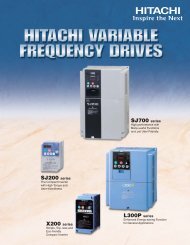
You also want an ePaper? Increase the reach of your titles
YUMPU automatically turns print PDFs into web optimized ePapers that Google loves.
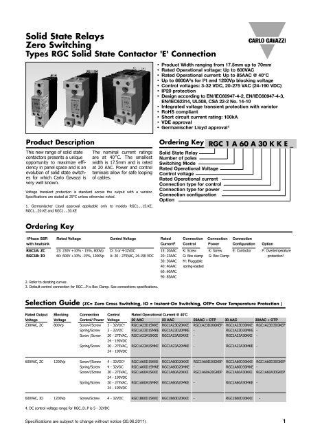
RGC...ESelection Guide (ZC= Zero Cross Switching, IO = Instant-On Switching, OTP = Over Temperature Protection ) (cont)Rated Output Blocking Connection Control Voltage Rated Operational Current @ 40˚CVoltage Voltage Control/ Power 40AAC 40AAC + OTP 60AAC 60AAC + OTP230VAC, ZC 800Vp Screw/Box Clamp 3 - 32VDC RGC1A23D40KGE - RGC1A23D60KGE -Spring/Box Clamp 3 - 32VDC RGC1A23D40MGE - - -Screw/Box Clamp 20 - 275VAC, 24 - 190VDC RGC1A23A40KGE - RGC1A23A60KGE -Spring/Box Clamp 20 - 275VAC, 24 - 190VDC RGC1A23A40MGE - - -600VAC, ZC 1200Vp Screw 3 /Box Clamp 4 - 32VDC 4 RGC1A60D40KGE RGC1A60D40GGEP RGC1A60D60KGE RGC1A60D60GGEPSpring/Box Clamp 4 - 32VDC RGC1A60D40MGE - - -Screw 3 /Box Clamp 20 - 275VAC, 24 - 190VDC RGC1A60A40KGE RGC1A60A40GGEP RGC1A60A60KGE RGC1A60A60GGEPSpring/Box Clamp 20 - 275VAC, 24 - 190VDC RGC1A60A40MGE - - -600VAC, IO 1200Vp Screw/Box Clamp 4 - 32VDC RGC1B60D40KGE - RGC1B60D60KGE -Rated Output Blocking Connection Control Voltage Rated Operational Current @ 40˚CVoltage Voltage Control/ Power 85AAC + fan + OTP230VAC, ZC 800Vp Box Clamp/Box Clamp 5 - 32VDC RGC1A23D90GGEP600VAC, ZC 1200Vp Box Clamp/Box Clamp 5 - 32VDC RGC1A60D90GGEPBox Clamp/Box Clamp 20 - 275VAC, 24 - 190VDC RGC1A60A90GGEP3. Default control connection for RGC...P is Box Clamp. See connections specifications.4. DC control voltage range for RGC..D..P is 5 - 32VDCOutput Voltage SpecificationsRGC..23..RGC..60..Operational Voltage Range 24-240 VAC, 42-600 VAC,+10%, -15% on max +10% -15% on maxBlocking Voltage 800Vp 1200 VpInternal Varistor 275V 625VGeneral SpecificationsLatching voltage(across L1-T1)Operational frequencyrangePower factorFinger ProtectionControl input status≤20V45 to 65Hz> 0.5 @ VratedIP20continuously ON Green LED,when control input is appliedPollution degree 2(non-conductive pollution withpossibilities of condensation)Over-voltage category III(fixed installations)IsolationInput to Output RGC... 4000 VrmsRGC...D..P 2500 VrmsRGC...A..P 4000 VrmsInput and Output RGC... 4000 Vrmsto case RGC...D..P 4000 VrmsRGC...A..P 4000 VrmsInput to Fan/ Alarm OutputRGC...A..P 2500 Vrms2 Specifications are subject to change without notice (30.06.2011)
RGC...EOutput specifications (@ 25°C unless otherwise specified)RGC..15.. RGC..20.. RGC..30.. RGC..40.. RGC..60.. RGC..90..Rated operational current 6AC-51 rating @ Ta=25°C 20 AAC 25.5 AAC 30 AAC 47.4 AAC 70.4 AAC 85 AACAC-51 rating @ Ta=40°C 20 AAC 23 AAC 30 AAC 40 AAC 60 AAC 85 AACAC-53a rating @ Ta=40°C 5 AAC 5 AAC 8 AAC 13 AAC 14.8 AAC 18 AACNumber of motor starts(x:6, Tx:6s, F:50%) at 40˚C 5 30 30 30 30 30 30Min. operational current 150 mAAC 150 mAAC 250 mAAC 400 mAAC 400 mAAC 400 mAACRep. overload current -(Motor Rating) PF = 0.4 - 0.5UL508: T AMB=40°C, t ON=1s, t OFF=9s,50cycles 60 AAC 60 AAC 84 AAC 126 AAC 144 AAC 168 AACMaximum transient surge current (I TSM) 325 Ap 325 Ap 600 Ap 800Ap 800Ap 1150ApMaximum off-state leakage current 3 mA 3 mA 3 mA 3 mA 3 mA 3 mAI²t (10ms) Minimum 525 A²s 525 A²s 1800 A²s 3200A²s 3200A²s 6600A²sCrititcal dv/dt (@ Tj init = 25°C) 1000 V/us 1000 V/us 1000 V/us 1000 V/us 1000 V/us 1000 V/us5. Overload current profle definition: x: multiple of AC53a rating, Tx: duration of current surge, F: duty cycle6. See derating curvesOvertemperature alarm specifications for RGC...PRGC..D..PRGC..A..POutput type PNP open collector Potential FreeNormal state Closed ClosedMaximum current rating 50 mADC 50 mADCRated voltage (EN61131-2: 2003) 8,7 , Ua 24VDC -15%, +20% 24VDC -15%, +20%Rated voltage, Us RGC...D90GGEP 24VDC ± 10% N/AFan rating, Uf RGC...A90GGEP N/A 24VDC ±10%, 50mA nominalAlarm voltage drop Typical 2.8VDC 1.8VDCMaximum 4VDC 3.5VDCVisual Indication Continous Red LED Continous Red LEDReverse polarity protection 24VDC 24VDC7: DC supply for alarm signal should be supplied from a Class 2 power source8: Maximum voltage to be applied between 11+ and 12- (Ua) terminals should be 35VDC maximum with reference to A2-Specifications are subject to change without notice (30.06.2011) 3
RGC...EInput specifications (cont.)RG..D..25.0mARGC..D..P(Normal Operation)A1 Characteristics: DC input current vs Input voltage x20.0mA15.0mARGC..D..P(Active Protection)10.0mA5.0mA2V 4V 6V 8V 10V 12V 14V 16V 18V 20V 22V 24V 26V 28V 30V 32V 34Vx: Input currents for RGC1..D15, RGC1..D20, RGC1..D30, RGC1..D40, RGC1..D6020.0mAIN1 Characteristics: DC input current vs Input voltageyx15.0mARGC..D90GGEP(Normal Operation)10.0mA5.0mARGC..D90GGEP(Active Protection)0.0mA2V 4V 6V 8V 10V 12V 14V 16V 18V 20V 22V 24V 26V 28V 30V 32V 34Vy: input currents valid only for RGC1..D90GGEPSpecifications are subject to change without notice (30.06.2011) 5
RGC...EMotor Ratings: HP (UL508) / kW (IEC60947-4-2) @ 40°C115 VAC 230 VAC 400 VAC 480 VAC 600 VACRGC..15 1/ 3 HP / 0.18kW 1HP / 0.37kW 2HP / 0.75kW 3HP / 1.1kW 3HP / 1.5kWRGC..20 ½HP / 0.18kW 1-½HP / 0.37kW 2HP / 0.75kW 3HP / 1.1kW 3HP / 1.5kWRGC..30 3/4HP / 0.37kW 2HP / 1.1kW 3HP / 1.5kW 5HP / 2.2kW 5HP / 3.7kWRGC..40 1HP / 0.56kW 3HP / 1.5kW 5HP / 2.2kW 5HP / 3.7kW 7-½HP / 4kWRGC..60 1-½HP / 0.56kW 3HP / 1.5kW 5HP / 3kW 7-½HP / 4kW 10HP / 4kWRGC..90GGEP 2HP / 0.75kW 5HP / 1.5kW 7½HP / 4kW 10HP / 4kW 15HP / 5.5kWDetailed Over temperature Alarm Procedure (for RGC...P)ALARM Signal and Fan(applicable ALARM to RGC..D90GGEP) Signal and FANALARM Signal onlyALARM Signal onlySTARTSTARTIs Chiptemperature >115°C ?NChiptemperaturelimit reached?NYYFAN: ONSSR output:Red LED:Alarm Signal:OFFONONChiptemperature
RGC...EOutput Power DissipationC WP 08R G C 1xyyz….C WP 15R G C 1.. power C WP x5 dis s ipation C WP vs 25 load c urrent C WP 30 C WP 30 C WP 41C urrent R G C 1..20 R G C 1..30 R G C 1..30 R G H1..20 R G C 1..40 R G C 1..60 R G C 1..90100W0 0.000 0.000 0.000 0.000 0.000 0.000 0.0001 0.654 0.624 0.624 0.565 0.630 0.630 0.5782 1.411 1.347 1.347 1.235 1.342RGC1..601.342 1.246390W2.216 2.111 2.111 1.951 2.090 2.090 1.9514 3.058 2.905 2.905 2.700 2.862 2.862 2.682R RGC1..90GGEPG C .580W3.931 3.723 3.723 3.478 3.655 3.655 3.4346 4.832 4.562 4.562 4.281 4.464 4.464 4.2037 5.759 5.419 5.419 5.105 5.288 5.288 4.988870W6.710 6.293 6.293 5.951 6.127 6.127 5.7879 7.684 7.183 7.183 6.816 6.978 6.978 6.60010 60W 8.680 8.088 8.088 7.699 RGC1..40 R G C 1..407.841 7.841 7.42411 9.697 9.008 9.008 8.600 8.715 8.715 8.26112 10.736 9.940 9.940 9.518 9.601 9.601 9.10850W13 11.795 10.886 10.886 10.453 10.497 10.497 9.96614 12.874 11.845 11.845 11.404 11.402 11.402 10.83415 40W 13.973 12.816 12.816 12.371 12.318 12.318 11.71116 15.091 13.799 13.799 13.353 13.243 13.243 12.59917 16.229 14.793 RGC1..30 14.793 14.351 14.178 14.178 13.49530W18 17.385 RGC1..20 15.799 15.799 15.363 15.121 15.121 14.40119 18.560 16.817 16.817 16.391 16.074 16.074 15.31620 20W 19.754RGC1..1517.845 17.845 17.432 17.035 17.035 16.23921 20.965 18.885 18.885 18.489 18.005 18.005 17.17122 22.195 19.935 19.935 19.559 18.983 18.983 18.11210W23 23.444 20.996 20.996 20.643 19.969 19.969 19.06024 24.710 22.067 22.067 21.742 20.964 20.964 20.017250W25.993 23.149 23.149 22.854 21.967 21.967 20.98226 0A 5A27.295 10A 15A 20A 24.24025A 30A24.240 35A 40A 45A 23.980 50A 55A 22.978 60A 65A 70A 22.978 75A 80A 21.955 85A 90A27 28.614 25.343 25.343 L oad c urrent 25.119 in A A C rms 23.997 23.997 22.93528 29.951 26.455 26.455 26.272 25.024 25.024 23.924P ower dis s iaption in WCurrent Derating (UL508)9080RGC .. 9070Load Current in AAC6050403020RGC .. 30RGC .. 20RGC .. 15RGC .. 60RGC .. 401000 10 20 30 40 50 60 70 80Surrounding Ambient Temperature in CRGC...P models max. operating temperature is + 70˚CSpecifications are subject to change without notice (30.06.2011) 7
RGC...EDerating vs. Spacing CurvesRGC.. 15..25Load Curre ent in AAC20151050mm5mm00 10 20 30 40 50 60 70 80Surrounding Ambient Temperature in °C10mm &overRGC.. 20..35Load Curre ent in AAC3025201510500 10 20 30 40 50 60 70 80Surrounding Ambient Temperature in °C0mm5mm10mm20mm &overRGC.. 30..35Load Curren nt in AAC3025200mm5mm1510mm &over100 10 20 30 40 50 60 70 80Surrounding Ambient Temperature in °CStandalone unit8 Specifications are subject to change without notice (30.06.2011)
Derating vs. Spacing CurvesRGC.. 40..5045nt in AACLoad Curre403530252015100 10 20 30 40 50 60 70 80Surrounding Ambient Temperature in °C0mm10mm &overStandaloneunitRGC.. 60..70Load Curre ent in AAC65605550454035300 10 20 30 40 50 60 70 80Surrounding Ambient Temperature in °C0mm10mm &overStandalone unitRGC.. 90GGEP90Load Curre ent in AAC85807570656055500 10 20 30 40 50 60 70Surrounding Ambient Temperature in °C0mm10mm &overStandalone unitSpecifications are subject to change without notice (30.06.2011) 9
RGC...EAgency Approvals and ConformancesConformance IEC/EN 62314IEC/EN 60947-4-2IEC/EN 60947-4-3Agency ApprovalsShort Circuit Current RatingUL508 Listed (E172877)cUL Listed (E172877)VDE 0660-109GL 12100kA, UL508Electromagnetic CompatibilityEMC Immunity IEC/EN 61000-6-2Electrostatic Discharge (ESD)Immunity IEC/EN 61000-4-2Air discharge, 8kV Performance Criteria 1Contact, 4kV Performance Criteria 1Electrical Fast Transient(Burst) Immunity IEC/EN 61000-4-4Output: 2kV, 5kHz Performance Criteria 1Input: 1kV, 5kHz Performance Criteria 1Electrical Surge Immunity IEC/EN 61000-4-5(for RGC...E)Output, line to line, 1kV Performance Criteria 1Output, line to earth, 2kV Performance Criteria 1Input, line to line, 1kV Performance Criteria 2Input, line to earth, 2kV Performance Criteria 2Electrical Surge Immunity IEC/EN 61000-4-5(for RGC...EP)Output, line to line, 1kV Performance Criteria 1Output, line to earth, 2kV Performance Criteria 1DC lines, line to line, 500V Performance Criteria 2DC lines, line to earth, 500V Performance Criteria 2Signal lines, line to earth, 1kV Performance Criteria 2Radiated Radio FrequencyImmunity IEC/EN 61000-4-310V/m, 80 - 1000 MHz Performance Criteria 110V/m, 1.4 - 2 GHz Performance Criteria 13V/m, 2 - 2.7 GHz Performance Criteria 1Conducted Radio Frequency IEC/EN 61000-4-6Immunity10V/m, 0.15 - 80 MHz Performance Criteria 1Voltage Dips Immunity IEC/EN 61000-4-110% for 10ms/20ms, Performance Criteria 240% for 200ms Performance Criteria 270% for 500ms Performance Criteria 2Voltage Interruptions Immunity IEC/EN 61000-4-110% for 5000ms Performance Criteria 2EMC Emission IEC/EN 61000-6-4Radio InterferenceVoltage Emission (Conducted) IEC/EN 550110.15 - 30MHz Class A (industrial) with filters- see filter informationIEC/EN 60947-4-2, 60947-4-3Class A (no filtering needed)Radio InterferenceField Emission (Radiated) IEC/EN 5501130 - 1000MHz Class A (industrial)Environmental SpecificationsOperating Temperature 11Storage TemperatureRoHS (2002/95/EC)Impact resistance(EN50155, EN61373)-40°C to 80°C (-40˚F to +176˚F)-40°C to 100°C (-40˚F to +212˚F)Compliant15/11 g/msVibration resistance(2-100Hz, IEC60068-2-26,EN50155, EN61373)Relative humidityUL flammability rating(housing)2g per axis95% non-condensing @ 40˚CUL 94 V011. Operating temperature range for RGC..P (overtemperature protection) is -30˚C to 70˚C (-22˚F to 158˚F)12. Applicable to models RGC1...15.KE, RGC1...20.KE and RGC1...30.KE10 Specifications are subject to change without notice (30.06.2011)
RGC...EFiltering - EN / IEC 55011 Class A compliance (for class B compliance contact us)Part Number Suggested filter for compliance Maximum Heater currentRGC1A23..15 68nF/ 275 V / X1 20ARGC1A23..20 68nF/ 275 V / X1 20ARGC1A23..30 220 nF / 275V / X1 30ARGC1A23..40 220 nF / 275V / X1 30A330 nF / 275V / X1 45ARGC1A23..60 220 nF / 275V / X1 30A330 nF / 275V / X1 45ARGC1A23..90GGEP 330 nF / 275V / X1 35A470 nF / 275V / X1 65ARGC1A60..15 100 nF / 760V / X1 20ARGC1A60..20 100 nF / 760V / X1 20ARGC1A60..30 220 nF / 760V / X1 30ARGC1A60..40 220 nF / 760V / X1 25A330 nF / 760V / X1 45ARGC1A60..60 220 nF / 760V / X1 25A330 nF / 760V / X1 45ARGC1A60..90GGEP 330 nF / 760V / X1 40A470 nF / 760V / X1 65ANote:• Control input lines must be installed together to maintain products' susceptability to Radio Frequency interference.• Use of AC solid state relays may, according to the application and the load current, cause conducted radio interferences. Use of mains filters may benecessary for cases where the user must meet E.M.C requirements. The capacitor values given inside the filtering specification tables should be taken onlyas indications, the filter attenuation will depend on the final application.• Performance Criteria 1: No degradation of performance or loss of function is allowed when the product is operated as intended.• Performance Criteria 2: During the test, degradation of performance or partial loss of function is allowed. However when the test is complete theproduct should return operating as intended by itself.• Performance Criteria 3: Temporary loss of function is allowed, provided the function can be restored by manual operation of the controls.Filter Connection Diagrams1 Phase 3 PhaseL1L2L3SSRSSRSSRLOADNR dR dR dR d = 1MΩ, 0.5WFilter has to be connectedacross both LOAD and SSRSpecifications are subject to change without notice (30.06.2011) 11
RGC...EConnection Diagram (No OTP)AC ControlledDC ControlledA1 ~ 1 L1A2 - 2 T1In AC controlled types only (RG..A..) avaristor is placed across A1/A2 terminals.In DC controlled types only (RG..D..) a diode is placed in serieswith the control circuit for protection against reverse biasedconnection.Connection Diagram (with OTP)RGC1...D20GKEPRGC1...D30GKEPRGC1...D40GGEPRGC1...D60GGEPRGC1...D90GGEPRGC1...A20GKEPRGC1...A30GKEPRGC1...A40GGEPRGC1...A60GGEPRGC1...A90GGEPUc: 5 - 32 VDCUa: max 35VDCAlarm Output: max. 50mAUc: 5 - 32 VDCUs: 24 VDCAlarm Output: max. 50mAUc: 24 - 275 VAC24 - 190 VDCUa: max 35VDCAlarm Output: max. 50mAUc: 24 - 275 VAC24 - 190 VDCUa: max. 35 VDCAlarm Output: max. 50mAUf: 24 VDC12 Specifications are subject to change without notice (30.06.2011)
RGC...ETerminal Layout and DimensionsRGC...15KKE17.8 598.59.55135.510698903.243.8RGC...15MKE1L117.89.55109.59245.535.5RG Solid State SwitchA1 L1A2 T1ONA1 A210698903.243.82T11/L1: Supply connection2/T1: Load connectionA1 (+): Positive control signalA2 (-): Control ground* Housing width tolerance +0.5mm, -0mm…as per DIN43880All dimensions in mmSpecifications are subject to change without notice (30.06.2011) 13
Terminal Layout and Dimensions (cont).RGC...20KKE17.8 51369.55135.510698903.217.89.55147129.545.535.510698903.217.822.59.5 51365135.510698903.243.843.843.8RGC...20MKE1L1State SwitchA1L1RG SolidA2 T1ONA1 A22T1RGC...30KKE1/L1: Supply connection2/T1: Load connectionA1 (+): Positive control signalA2 (-): Control ground* Housing width tolerance +0.5mm, -0mm…as per DIN43880All dimensions in mm14 Specifications are subject to change without notice (30.06.2011)
RGC...ETerminal Layout and Dimensions (cont.)RGC...30MKE1L122.59.55147129.5SwitchStateA1L13.2RG SolidA1A2ONT1A243.82T1RGC...40KGE5143.7136535.627.23.2R G S olid S tate S witchA1 L1A2 T1ONA1 A243.81069890RGC...40MGE1L1147129.5535.627.2R G S olid S tate S witchA1 L1A2 T1ONA1 A23.2106989043.82T11/L1: Supply connection2/T1: Load connectionA1 (+): Positive control signalA2 (-): Control ground* Housing width tolerance +0.5mm, -0mm…as per DIN43880All dimensions in mmSpecifications are subject to change without notice (30.06.2011) 15
RGC...ETerminal Layout and Dimensions (cont.)RGC...60KGE5143.7136 569.135.627.2R G S olid S tate S witchA1 L1A2 T1ONA1 A23.2106989043.8RGC...20GKEP22.517.89.51L17835.51635ALARMALARM11 + 12 -SUPPLYA1A11069890SwitchRG Solid StateCONTROLFAULTA2GNDGND2T1RGC...30GKEP1L17835.5163522.59.5ALARMALARM11 + 12 -SUPPLYA1A1RG Solid State SwitchCONTROL1069890FAULTA2GNDGND2T11/L1: Supply connection2/T1: Load connectionA1 (+): Positive control signal(Positive supply in case of RGC1A..D90GGEP)A2 (-): Control groundIN1: Control signal (only for RGC1A.. D 90GGEP)IN2: Fan + supply (only for RGC1A60A90GGEP)IN3: Fan - supply (only for RGC1A60A90GGEP)11 + : Alarm output (+)OUT, 12 - : Alarm output (-)* Housing width tolerance +0.5mm, -0mm…as per DIN43880All dimensions in mm16 Specifications are subject to change without notice (30.06.2011)
ALARMFAN +CONTROLFAN -SUPPLYGNDRGC...ETerminal Layout and Dimensions (cont.)RGC...40GGEP78 43.7167.8163535.627.2IN2 IN3 A2106989060.5RGC...60GGEP7843.7163569.127.21069890IN2IN3A2RGC...90GGEP7843.7163569.127.2OUTIN1A111+12-A111+12-A111+12- A1RG Solid State SwitchIN2IN3CONTROLFAULTA2IN2IN3 A2126989060.5RGC...D90GGEPRGC...A90GGEP1/L1: Supply connection2/T1: Load connectionA1 (+): Positive control signal(Positive supply in case of RGC1A..D90GGEP)A2 (-): Control groundIN1: Control signal (only for RGC1A.. D90GGEP)IN2: Fan + supply (only for RGC1A60A90GGEP)IN3: Fan - supply (only for RGC1A60A90GGEP)11 + : Alarm output (+)OUT, 12 - : Alarm output (-)* Housing width tolerance +0.5mm, -0mm…as per DIN43880All dimensions in mmSpecifications are subject to change without notice (30.06.2011) 17
RGC...EConnection SpecificationsPOWER CONNECTIONS: 1/L1, 2 /T1Use 75°C copper (Cu) conductors RGC..15.KE. ; RGC..20.KE. ; RGC..30.KE. RGC..40.GE. ; RGC..60.GE. ; RGC..90GGEPStripping Length (X) 12mm 11mmConnection type M4 screw with captivated washer M5 screw with box clampRigid (Solid & Stranded)UL/ cUL rated dataX2 x 2.5..6 mm 2 1 x 2.5..6 mm 2 1 x 6..25mm 22 x 14.. 10 AWG 1 x 14.. 10 AWG 1 x 10...3 AWGFlexible with end sleeve 2 x 1.0 ... 2.5mm 22 x 2.5..4mm 2 1 x 1.0..4mm 2 1 x 2.5..16mm 22 x 18.. 14 AWG 1 x 18.. 12 AWG 1 x 14.. 6 AWG2 x 14.. 12 AWGFlexible without 2 x 1.0 ... 2.5mm 2end sleeve 2 x 2.5.. 6mm 2 1 x 1.0.. 6mm 2 1 x 4.. 25mm 22 x 18.. 14 AWG 1 x 18.. 10 AWG 1 x 12.. 3 AWG2 x 14.. 10 AWGTorque specifications 2 Nm (17.7 in-lb). 2.5 Nm (22 in-lb).M4, Pozidriv 2 M5, Pozidriv 2Aperture for termination lug 12.3mm N/AProtective Earth ConnectionRGC..15, 20: M4, 1.5Nm (13.3 in-lb)RGC..30, 40, 60, 90: M5, 1.5Nm (13.3 in-lb)Note: Protective Earth connection must be connected whenever the product is intended to be used in Class 1 applications according to EN/IEC 61140.CONTROL CONNECTIONS: A1(+), A2(-)Use 60/75°C copper (Cu) conductorsRGC..K.ETorque specifications 0.5 Nm (4.4 in-lb); M3, Pozidriv 1RGC....M.EStripping Length (X) 8mm 12 - 13mmRigid (Solid & Stranded)UL/ cUL rated dataXFlexible with end sleeve2 x 0.5..2.5mm 2 1 x 0.5..2.5mm 2 1 x 0.2...2.5mm 22 x 18..12 AWG 1 x 18..12 AWG 1 x 24...12 AWG2 x 0.5..2.5mm 2 1 x 0.5..2.5mm 22 x 18..12AWG 1 x 18..12AWGCONTROL CONNECTIONS: A1(+), A2(-), IN1, IN2, IN3, 11 (+), 12(-), OUTUse 60/75°C copper (Cu) conductors RGC...GGEPTorque specifications 0.5 Nm (4.4 in-lb); M3, Pozidriv 1Stripping Length (X) 6mm 13mmRigid (Solid & Stranded)UL/ cUL rated dataXFlexible with end sleeve2 x 0.5..2.5mm 2 1 x 0.2..2.5mm 22 x 18..12 AWG 1 x 24..12 AWG2 x 0.5..2.5mm 2 1 x 0.2..2.5mm 22 x 18..12AWG 1 x 24..12AWG18 Specifications are subject to change without notice (30.06.2011)
RGC...EInstallation InstructionsY1 = 5mmX =X = Refer toproductDerating vs.Spacing widthCurvesY2 =100mmShort Circuit ProtectionProtection Co-ordination, Type 1 vs Type 2:Type 1 protection implies that after a short circuit, the device under test will no longer be in a functioning state. In type 2 co-ordination the device under testwill still be functional after the short circuit. In both cases, however the short circuit has to be interrupted. The fuse between enclosure and supply shall notopen. The door or cover of the enclosure shall not be blown open. There shall be no damage to conductors or terminals and the condcutors shall not separatefrom terminals. There shall be no breakage or cracking of insulating bases to the extent that the integrity of the mounting of live parts is impaired.Discharge of parts or any risk of fire shall not occur.The product variants listed in the table hereunder are suitable for use on a circuit capable of delivering not more than 100,000A rms Symmetrical Amperes,600 Volts maximum when protected by fuses. Tests at 100,000A were performed with Class J fuses, fast acting; please refer to the table below for maximumallowed ampere rating of the fuse. Use fuses only.Co-ordination type 1 (UL508)Part No. Max. size [A] Class Current [kA] Voltage [VAC]RGC..15 30 J 100 Max. 600RGC..20 30 J 100 Max. 600RGC..30 30 J 100 Max. 600RGC..40 30 J 100 Max. 600RGC..60 30 J 100 Max. 600RGC..90GGEP 40 J 100 Max. 600Co-ordination type 2 (IEC EN 60947-4-2/ -4-3)Part No. Ferraz Shawmut Siba Current [kA] Voltage [VAC]Max size [A] Part number Max size [A] Part numberRGC..15 32 6.9xx CP URD 22x58/32(xx=00 or 21) 32 50 142 06.32 100 Max. 600RGC..20 32 6.9xx CP URD 22x58/32(xx=00 or 21) 32 50 142 06.32 100 Max. 600RGC..30 40 A70QS40-4 32 50 142 06.32 100 Max. 600RGC..40 70 A70QS70-4 63 50 194 20.63 100 Max. 600RGC..60 90 A70QS90-4 80 50 194 20.80 100 Max. 600RGC..90GGEP 100 A70Q5100-4 100 50 194 20.100 100 Max. 600Specifications are subject to change without notice (30.06.2011) 19
RGC...EProtection with Miniature Circuit BreakersSolid State Relay Model no. for Model no. for Wire cross Minimum length oftype Z - type M. C. B. B - type M. C. B. sectional area [mm2] Cu wire conductor [m] 13(rated current)(rated current)RGC..15, RGC..20 S201 - Z4 (4A) S201 - B2 (2A) 1.0 21.0S201 - Z6 UC (6A) S201 - B2 (2A) 1.0 21.01.5 31.5RGC..30 S201 - Z10 (10A) S201-B4 (4A) 1.0 7.61.5 11.42.5 19.0S201 - Z16 (16A) S201-B6 (6A) 1.0 5.21.5 7.82.5 13.04.0 20.8S201 - Z20 (20A) S201-B10 (10A) 1.5 12.62.5 21.0S201 - Z25 (25A) S201-B13 (13A) 2.5 25.04.0 40.0S202 - Z25 (25A) S202-B13 (13A) 2.5 19.04.0 30.4RGC..40 S201 - Z25 (25A) S201-B13 (13A) 2.5 7.04.0 11.26.0 16.8RGC..60 S201 - Z25 (25A) S201-B13 (13A) 2.5 7.04.0 11.26.0 16.8RGC..90GGEP S201 - Z20 (20A) S201-B10 (10A) 1.5 4.22.5 7.04.0 11.2S202 - Z20 (20A) S202-B10 (10A) 1.5 1.82.5 3.04.0 4.8S201 - Z32 (32A) S201-B16 (16A) 2.5 13.04.0 20.86.0 31.2S202 - Z32 (32A) S202-B16 (16A) 2.5 5.04.0 8.06.0 12.010.0 20.0S202 - Z50 (50A) S202-B25 (25A) 4.0 14.86.0 22.210.0 37.013. between MCB and SSR Relay (including return path which goes back to the mains).Note: A prospective current of 6kA and a 230/400V power supply system is assumed for the above suggested specifications. For cables with different crosssection than those mentioned above please consult Carlo Gavazzi's Technical Support Group.20 Specifications are subject to change without notice (30.06.2011)