KIT: CERES 8000i FOR CLAAS LEXION AND TUCANO KIT REF: P ...
KIT: CERES 8000i FOR CLAAS LEXION AND TUCANO KIT REF: P ...
KIT: CERES 8000i FOR CLAAS LEXION AND TUCANO KIT REF: P ...
- No tags were found...

Create successful ePaper yourself
Turn your PDF publications into a flip-book with our unique Google optimized e-Paper software.
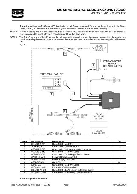
<strong>KIT</strong>: <strong>CERES</strong> <strong>8000i</strong> <strong>FOR</strong> <strong>CLAAS</strong> <strong>LEXION</strong> <strong>AND</strong> <strong>TUCANO</strong><strong>KIT</strong> <strong>REF</strong>: P/<strong>CERES</strong>8K/LEX12These instructions are for Ceres <strong>8000i</strong> installation on all Claas Lexion and Tucano combines fitted with the ClaasQuantimeter (i.e. the machine is already has grain yield sensor and moisture sensors installed).NOTE 1: If yield mapping, the forward speed input for the Ceres <strong>8000i</strong> is normally taken from the GPS receiver, thereforethere is no need to install a forward speed sensor [6] on the drive shaft.NOTE 2: The <strong>CLAAS</strong> sensor is a "batch" sensor that takes a periodic reading when the sensor housing fills. If a continuousmoisture reading is required, then a separate moisture sensor must be installed (instructions supplied with sensorkit).Fig. 156<strong>FOR</strong>WARD SPEEDSENSOR(SEE NOTE ABOVE)<strong>CERES</strong> <strong>8000i</strong> HEAD UNIT7POWER SUPPLY1423Item Part Number Description Qty1 S/HU/268-3-020 Ceres <strong>8000i</strong> Head Unit 12 K/CER8Ki/JBi2 Ceres "i" Mk2 Junction Box Kit 13 S/CB/182-3-063 Claas Lexion Yield/Moisture Sensor Loom 14 S/CB/268-3-010 Ceres <strong>8000i</strong> Head Unit Cable 15 S/CB/182-3-062 Claas Lexion Table Height Sensor Loom 16 K/PROP SHAFT Forward Speed Sensor Kit 17 S/CB/500-1-022 Power Supply Lead (5A) 1# S/CBL/TIE/001 Cable Tie 50# S/Z780-563 Ceres <strong>8000i</strong> Head Unit Label 1# S/DC/500-10-183 Installation/Calibration Data 1# S/DC/500-10-706 Ceres <strong>8000i</strong> <strong>CLAAS</strong> Lexion Installation Leaflet 1# S/DC/500-10-584 Ceres <strong>8000i</strong> Calibration / Operation Manual 1# denotes part not illustratedDoc. No. S/DC/500-10-706 : Issue 1 - 20.6.12 Page 1 UK706100.DOC
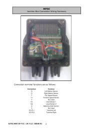
<strong>KIT</strong>: <strong>CERES</strong> <strong>8000i</strong> <strong>FOR</strong> <strong>CLAAS</strong> <strong>LEXION</strong> <strong>AND</strong> <strong>TUCANO</strong><strong>KIT</strong> <strong>REF</strong>: P/<strong>CERES</strong>8K/LEX12Installing the <strong>CLAAS</strong> Cable LoomsYield/Moisture Sensor Loom:Fig. 2Insert the 5-way connectors in between the Moisture Sensor plug and socket connection, located adjacent to thesensor on the clean grain elevator (fig. 2).Identify the Grain Yield Sensor Receiver on the clean grain elevator (fig.2). The receiver will be labelled"Empfänger". Trace the loom from the receiver back to the <strong>CLAAS</strong> connector. Insert the 3-way connectors inbetween the Grain Yield Sensor Receiver plug and socket connection, located adjacent to the sensor on the cleangrain elevator.Route the loom back to the junction box following the <strong>CLAAS</strong> loom as appropriate. Refer to Table 2 for wiring intothe junction box.Yield SensorMoisture sensor connectorTable Height Sensor Loom:Fig. 3Insert the 3-way connector in between the Table Height Sensor plug and socket connection, located on the sensor(fig.3).Route the loom back to the junction box following the <strong>CLAAS</strong> loom as appropriate. Refer to Table 2 for wiring intothe junction box.Doc. No. S/DC/500-10-706 : Issue 1 - 20.6.12 Page 2 UK706100.DOC
<strong>KIT</strong>: <strong>CERES</strong> <strong>8000i</strong> <strong>FOR</strong> <strong>CLAAS</strong> <strong>LEXION</strong> <strong>AND</strong> <strong>TUCANO</strong><strong>KIT</strong> <strong>REF</strong>: P/<strong>CERES</strong>8K/LEX12Head unitThe head unit should be mounted where convenient for the operator. For safety reasons, it should not affect theview from the driving seat.(a) Fit the mounting stalk [1] to the head unit with two M8 locking nuts [4].(b) Attach the mounting stalk (normally to the right hand top cab pillar) using the M8 x 20 hex. Screws [6].Figure 4aFigure 4b(c) Connect the cable [2] onto the head unit and route it back to the junction box. Refer to Table 1 for wiring into thejunction box.NOTE: If the cable is routed through a bulkhead, cut a 3/4" Ø hole and fit the grommet supplied to protect the cable fromchafing.Junction Box / Angle SensorMounting positionFigure 5:The junction box despite being weatherproof, should preferably be mounted inside the cab or cab-sidecompartment to afford maximum physical protection. The mounting position should also allow ease of routing thevarious sensor cables through bulkheads etc.To enable correct operation of the integral angle sensor, mount the box VERTICALLY using M6 x 25 screws [2],and oriented as shown in figure 5. For some machines, it may be necessary to fabricate a suitable bracket(bracket not supplied).Angle Sensor orientationFRONTDoc. No. S/DC/500-10-706 : Issue 1 - 20.6.12 Page 3 UK706100.DOC
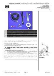
<strong>KIT</strong>: <strong>CERES</strong> <strong>8000i</strong> <strong>FOR</strong> <strong>CLAAS</strong> <strong>LEXION</strong> <strong>AND</strong> <strong>TUCANO</strong><strong>KIT</strong> <strong>REF</strong>: P/<strong>CERES</strong>8K/LEX12Cable entryThe head unit cable is fitted through the centre grommet. All other sensor cables should be fitted through thesmaller grommets. Cut off the tip of the chosen cable entry sleeve (fig. 6a) to feed the cable through, and fit a cabletie to give strain relief (fig. 6b)Figure 6a: Figure 6b:Forward Speed SensorKit ref. K/PROP/SHAFTThe Ceres is supplied as standard with a magnetically-operated speed sensor operating from a drive shaft. Thiscan be installed on any exposed shaft that rotates at a speed proportional to ground speed, i.e. where there is afixed gearing ratio between the shaft and the wheel.Mounting the forward speed sensorThe sensor and magnet can be arranged as convenient to ensure that:-(i) the magnet passes the sensor in either of the relationships shown (figure 7).(ii) the end of the sensor protrudes at least 20mm (3/4") from the mounting bracket.(iii) the gap between the sensor and magnet is between 10mm (1/4" ) and 15mm (5/8").Figure 7 Correct sensor-magnet relationshipGOODGOODPosition the magnet carrier [4] opposite the hose clip screw (figure 7). Ideally the sensor and magnet assemblyshould be positioned where it is afforded maximum protection from being hit by objects passing under theharvester. For example it can be mounted above the drive shaft and behind the axle beam on New Hollandharvesters.Do not position the sensor in relation to the magnet as shown in figure 8. In this position the sensor will not givereliable operation.Route the cable forward to the junction box. Cable-tie where possible to an existing wiring loom or hydraulic lines.Refer to Table 2 for wiring into the junction box.Doc. No. S/DC/500-10-706 : Issue 1 - 20.6.12 Page 4 UK706100.DOC
<strong>KIT</strong>: <strong>CERES</strong> <strong>8000i</strong> <strong>FOR</strong> <strong>CLAAS</strong> <strong>LEXION</strong> <strong>AND</strong> <strong>TUCANO</strong><strong>KIT</strong> <strong>REF</strong>: P/<strong>CERES</strong>8K/LEX12Figure 8: Incorrect sensor-magnet relationshipBADWiring ConnectionsFigure 9:Doc. No. S/DC/500-10-706 : Issue 1 - 20.6.12 Page 5 UK706100.DOC
<strong>KIT</strong>: <strong>CERES</strong> <strong>8000i</strong> <strong>FOR</strong> <strong>CLAAS</strong> <strong>LEXION</strong> <strong>AND</strong> <strong>TUCANO</strong><strong>KIT</strong> <strong>REF</strong>: P/<strong>CERES</strong>8K/LEX12Table 1:Head Unit Connections – Cable Ref. S/CB/268-3-010Function Terminal Ref Wire Colour0V CON 3-1 Black+V CON 3-2 Red0V CON 3-3 BlueTable Height Sensor "TABLE HEIGHT OPTION" GreenTemperature CON 3-5 WhiteMoisture CON 3-6 GreyAngle: Left-Right CON 3-7 VioletAngle: Forward-Aft CON 3-8 BrownArea Cutout CON 3-9 -Yield Sensor 2 CON 3-10 TanYield Sensor 1 CON 3-11 YellowForward Speed CON 3-12 OrangeTable 2:Sensor ConnectionsSensor CON 1/2 Terminal Ref. Wire Colour+V (Not used) -Forward Speed SensorSIGBrown(“FWD SPEED”)0VBlue+V -TEMPBlueMoisture SensorSIG -Black(“MOISTURE SNR ”)SIG +White0V -+V -Table Height Sensor+5V -(“TABLE HEIGHT”)SIGBrown0VBlue+V -External Angle Sensor [Note 2]0V -(“EXT ANG SNR”)F-A -L-R -Area Cutout Switch [Note 1]SIG -(“CUTOUT”)0V -Yield Sensor 1(“YIELD 1”)Yield Sensor 2(“YIELD 2”)+V -SIGYellow0VGreen+V -SIG -0V -[1] Please ignore – replaced by Table Height Sensor input.[2] Please ignore – integral angle sensor now supplied as standard spec.Doc. No. S/DC/500-10-706 : Issue 1 - 20.6.12 Page 6 UK706100.DOC