Deck Detail - Gloucester County Virginia
Deck Detail - Gloucester County Virginia
Deck Detail - Gloucester County Virginia
- No tags were found...

Create successful ePaper yourself
Turn your PDF publications into a flip-book with our unique Google optimized e-Paper software.
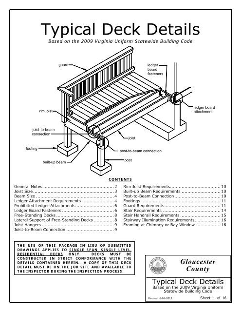
Typical <strong>Deck</strong> <strong>Detail</strong>sBased on the 2009 <strong>Virginia</strong> Uniform Statewide Building Codeguardledgerboardfastenersrim joistledger boardattachmentfootingjoist-to-beamconnectionbuilt-up beampost-to-beam connectionpostjoistGeneral Notes ................................................. 2Joist Size ........................................................ 3Beam Size ...................................................... 4Ledger Attachment Requirements ...................... 4Prohibited Ledger Attachments .......................... 6Ledger Board Fasteners .................................... 6Free-Standing <strong>Deck</strong>s ........................................ 8Lateral Support of Free-Standing <strong>Deck</strong>s .............. 8Joist Hangers .................................................. 9Joist-to-Beam Connection ................................. 9CONTENTSRim Joist Requirements ................................... 10Built-up Beam Requirements ........................... 10Post-to-Beam Connection ................................ 10Footings ....................................................... 11Guard Requirements ....................................... 11Stair Requirements ........................................ 14Stair Handrail Requirements ............................ 15Stairway Illumination Requirements .................. 16Framing at Chimney or Bay Window ................. 16THE USE OF THIS PACKAGE IN LIEU OF SUBMITTEDDRAWINGS APPLIES TO SINGLE SPAN, SINGLE LEVEL,RESIDENTIAL DECKS ONLY. DECKS MUST BECONSTRUCTED IN STRICT CONFORMANCE WITH THEDETAILS CONTAINED HEREIN. A COPY OF THIS DECKDETAIL MUST BE ON THE JOB SITE AND AVAILABLE TOTHE INSPECTOR DURING THE INSPECTION PROCESS.<strong>Gloucester</strong><strong>County</strong>Typical <strong>Deck</strong> <strong>Detail</strong>sBased on the 2009 <strong>Virginia</strong> UniformStatewide Building CodeRevised: 6-01-2013 Sheet 1 of 16
GENERAL NOTES1. All lumber shall be southern pine, grade #2 or better and shall be pressure treated ACQ or CA-B inaccordance with American Wood-Preservers' Association standards for ground contact.2. All nails shall be spiral or annular grooved.3. New pressure treatment methods use chemicals that will prematurely corrode standardfasteners, hardware, and flashing when in contact with pressure treated lumber, and, asa result, fastener and hardware requirements have changed; see below.‣ All screws and nails shall be hot-dipped galvanized or stainless steel.‣ All hardware (joist hangers, cast-in-place post anchors, etc.) shall be galvanized with1.85 oz/sf of zinc (G-185 coating) or shall be stainless steel. Look for products suchas "Zmax" from Simpson Strong-Tie or "Triple Zinc" from USP.4. <strong>Deck</strong>s constructed according to this handout are not approved for future hot tub installations.5. <strong>Deck</strong>s shall not be attached to house overhangs, bay windows, brick veneers, or chimneys.6. Deviations from this handout and conditions which do not meet the details shown herein require aplan submission.7. Inspections:‣ A footing, framing, and final inspection is required on all decks.‣ Footing inspections are required PRIOR to the placement of concrete.‣ Framing and final inspections may be combined if all portions of the deck framing andmechanical attachments are at least 42" above grade.‣ Inspections are required by law. Failure to receive any and all inspections can resultin the issuance of violations which may lead to legal proceedings.8. It is the responsibility of the permit holder or the permit holder's representative to notify the<strong>County</strong> when the stages of construction are reached that require an inspection. Inspectionrequests may be made by calling the <strong>County</strong> of <strong>Gloucester</strong> inspection request line (804) 693-2744during regular working hours, Monday through Friday 7:30 am – 4:30 pm or after hours (804)693-7037.9. All decking material shall be composed of 2x6 or 5/4 ("five-quarter") board. Attach decking toeach joist with 2-8d nails or 2-#8 screws. <strong>Deck</strong>ing may be placed from an angle perpendicular tothe joists to an angle of 45 degrees to the joists. <strong>Deck</strong>ing must have a span length such that eachboard bears on a minimum of 4 joists.10. Plastic or manufactured decking products may be substituted with an approved evaluation reportfrom the International Code Council. The evaluation report must be on the jobsite and available tothe inspector during the inspection process. Installation and span lengths of the substitutedmaterial must be in strict conformance with the evaluation report and the manufacturer'sinstructions.11. <strong>Deck</strong>s shall not be used or occupied until a finalinspection approval is obtained.<strong>Gloucester</strong><strong>County</strong>Typical <strong>Deck</strong> <strong>Detail</strong>sBased on the 2009 <strong>Virginia</strong> UniformStatewide Building CodeRevised: 6-01-2013 Sheet 2 of 16
JOIST SIZEThe span of a joist is measured from the centerline of bearing at one end of the joist to the centerline ofbearing at the other and does not include overhangs. Maximum joist span lengths are noted in TABLE 1.See FIGURE 1 and FIGURE 2 for joist span types.optional overhang3'-0"max.Joist Span(min. span = 6'-0" with overhang)FIGURE 1: JOIST SPAN - DECK ATTACHED AT HOUSE (SEE FIGURE 5)optional overhangoptional overhang3'-0"max.Joist Span(min. span = 6'-0" with overhang)FIGURE 2: JOIST SPAN - FREE-STANDING DECK3'-0"max.TABLE 1: MAXIMUM JOIST SPANSJoist Spacing,Joist SizeJoist Span 1on center (does not include overhang)2x6 16" 9'-0"2x6 24" 7'-7"2x8 16" 11'-10"2x8 24" 9'-8"2x10 16" 14'-0"2x10 24" 11'-5"2x12 16" 16'-6"2x12 24" 13'-6"1 Spans based on 40 PSF live load, 10 PSF dead load, southernpine#2, normal loading duration, wet service conditions andΔ=l/360.<strong>Gloucester</strong><strong>County</strong>Typical <strong>Deck</strong> <strong>Detail</strong>sBased on the 2009 <strong>Virginia</strong> UniformStatewide Building CodeRevised: 6-01-2013 Sheet 3 of 16
BEAM SIZEBeam size determination is based on your joist span characteristics. Use TABLE 2 if your joists do notoverhang or TABLE 3 if your joist overhangs. See FIGURE 3 for beam span types.optional overhangbeam splices atinterior postlocations onlyBeam Span8'-0" max.Beam Span8'-0" max.2'-0"max.FIGURE 3: BEAM SPAN TYPESTABLE 2: MINIMUM BEAM SIZEFOR JOISTS WITH NO OVERHANGSTABLE 3: MINIMUM BEAM SIZEFOR JOISTS WITH OVERHANGSJoist SpanBeam SizeJoist SpanBeam Size0 - 6'-8" (2) 2x6*0 – 6'-0" (2) 2x8*6'-8" - 11'-2" (2) 2x8*6'-0" – 12'-8" (2) 2x10*11'-2" – 15'-9" (2) 2x10*12'-8" – 18'-9"(2) 2x1216'-0" – 18'-9"(2) 2x12* You may substitute a larger beam size for the one shown in the table. For instance, if the table requires (2) 2x8, youmay substitute a (2) 2x10 or (2) 2x12.LEDGER ATTACHMENT REQUIREMENTSGENERAL: Ledger board attachments to the existing exterior wall shall be constructed in accordance withFIGURE 5 through FIGURE 7. When attachments are made to the existing house band board, it shall becapable of supporting the new deck. If this cannot be verified or conditions at the existing house differfrom the details herein, then a free-standing deck is required. See FREE-STANDING DECKS on sheet 8.YOU MUST VERIFY THE EXISTING CONDITIONS IN THE FIELD PRIOR TO APPLYING FOR A BUILDINGPERMIT. COMPLIANCE WITH ALL THE REQUIREMENTS HEREIN IS CRITICAL TO ENSURE THESTRUCTURAL STABILITY OF YOUR DECK.SIDING AND FLASHING: Siding or the exterior finish system must be removed prior to the installationof the ledger board. Flashing is required at any ledger board connection to a wall of wood framedconstruction and shall be composed of copper (attached using copper nails), stainless steel, UV resistantplastic or galvanized steel coated with 1.85 oz/sf of zinc (G-185 coating).FIGURE 4: MWJPROFILEMANUFACTURED WOOD JOIST: The term "MWJ" denotes manufactured wood "I"joists; see FIGURE 4. Examples of manufactured wood joists are TJI, GPI, andLPI.Many new homes constructed with MWJs include a 1- 1 / 4 " manufactured solid rimjoist; see FIGURE 5. However, older homesconstructed with MWJs may only include aplywood band board. In these cases a freestandingdeck or a full plan submission isrequired.<strong>Gloucester</strong><strong>County</strong>Typical <strong>Deck</strong> <strong>Detail</strong>sBased on the 2009 <strong>Virginia</strong> UniformStatewide Building CodeRevised: 6-01-2013 Sheet 4 of 16
FIGURE 5: ATTACHMENT OF LEDGER BOARD-TO-BAND BOARD MINIMUM OF TWO HOLD-DOWNOR SIMILAR TENSION DEVICES REQUIREDembed anchors2-1/2" min.concrete or solidmasonry walldeck joist1/2" dia.expansionanchors2x ledger boardFIGURE 6: ATTACHMENT OF LEDGER BOARD-TO-FOUNDATION WALL (CONCRETE OR SOLID MASONRY)embedanchors3-1/2"min.hollow masonry walldeckjoist8" min.2x ledger board1/2" dia.epoxyanchorsFIGURE 7: ATTACHMENT OF LEDGER BOARD-TO-FOUNDATION WALL (HOLLOW MASONRY)<strong>Gloucester</strong><strong>County</strong>Typical <strong>Deck</strong> <strong>Detail</strong>sBased on the 2009 <strong>Virginia</strong> UniformStatewide Building CodeRevised: 6-01-2013 Sheet 5 of 16
PROHIBITED LEDGER ATTACHMENTSAttachments to the ends of pre-manufactured open web joists, to brick veneers, and to houseoverhangs/bay windows are strictly prohibited; see FIGURE 8 through FIGURE 10. In such cases the deckshall be free-standing. See FREE-STANDING DECKS on sheet 8.open webfloor trussesdeckjoistdeckjoistbrickveneer ormasonrychimneyFIGURE 8: NO ATTACHMENTTO OPEN WEB TRUSSESFIGURE 9: NO ATTACHMENTTO BRICK VENEERFIGURE 10: NO ATTACHMENTTO HOUSE OVERHANGLEDGER BOARD FASTENERSAll fastener types shall be spaced per TABLE 4 and installed per FIGURE 11. All fasteners shall be installedwith washers and must be thoroughly tightened. Adequacy of connections will be verified by countyinspectors. If a ladder is required to access the ledger board, one must be provided by the propertyowner, permit holder, or their representative.Styp.2"typ.2"typ.lag screw, thru-bolt oranchor with washer, typ.FIGURE 11: LEDGER BOARD FASTENERSPACING AND CLEARANCESTABLE 4: LEDGER BOARD FASTENER SCHEDULEJoist SpanS (spacing),on center0 – 8' 10"8' – 10' 8"10' – 14' 6"14' – 18' 5"greater than 18' 4"<strong>Gloucester</strong><strong>County</strong>Typical <strong>Deck</strong> <strong>Detail</strong>sBased on the 2009 <strong>Virginia</strong> UniformStatewide Building CodeRevised: 6-01-2013 Sheet 6 of 16
Thru-BoltsThru-bolts shall have a minimum diameter of 1 / 2 ". Lead (pilot) holes for thru-bolts shall be 17 / 32 " to 9 / 16 "in diameter. Thru-bolts must be equipped with washers at the bolt head as well as the nut.Expansion AnchorsUse expansion anchors when attaching a ledger board to a concrete or solid masonry wall as shown inFIGURE 6. Bolt diameters of the anchors shall be a minimum of 1 / 2 "; in some cases, this may require ananchor size of 5 / 8 ". Minimum embedment length shall be 2- 1 / 2 ". Expansion anchors must have washers.Epoxy AnchorsWhen attaching to hollow masonry, fill the cells with grout and use expansion anchors, or use one of theapproved epoxy anchors listed in TABLE 5 and install as shown in FIGURE 7. Epoxy anchors shall have aminimum diameter of 1 / 2 " and minimum embedment length of 3- 1 / 2 ". Installation shall be in strictconformance to the manufacturers' instructions. Epoxy anchors must have washers.TABLE 5: APPROVED EPOXY ANCHORSManufacturerProductITW Ramset/Red Head Epcon Acrylic 7HiltiHY-20Lag ScrewsLag screws shall have a minimum diameter of 1 / 2 " and shall be hot-dipped galvanized or stainless steel.Lag screws may be used only when the field conditions match those shown in FIGURE 5. You mustverify the existing conditions in the field prior to applying for a building permit and installinglag screws. Compliance with all the requirements herein is critical to ensure the structuralstability of your deck. See FIGURE 12 for lag screw length and shank requirements. All lag screwsshall be installed with washers.1/2" dia.1-1/2" shank(no threads)length must extend throughexisting band board/rim joistlag screws must be hotdippedgalvanized orstainless steel onlyscrew must penetratebeyond band board/rimjoist a minimum of 1/2"FIGURE 12: LAG SCREW REQUIREMENTSLag screw installation requirements: each lag screw shall have lead (pilot) holes drilled as follows:1) drill a 1 / 2 " diameter hole in the ledger board, 2) drill a 5 / 16 " diameter hole into the solid connectionmaterial of the existing house. DO NOT DRILL A 1 / 2 " DIAMETER HOLE INTO THE SOLID CONNECTIONMATERIAL.The threaded portion of the lag screw shall be inserted into the lead hole by turning. DO NOT DRIVEWITH A HAMMER. Use soap or a wood-compatible lubricant as required to facilitate tightening. Eachlag screw shall be thoroughly tightened.<strong>Gloucester</strong><strong>County</strong>Typical <strong>Deck</strong> <strong>Detail</strong>sBased on the 2009 <strong>Virginia</strong> UniformStatewide Building CodeRevised: 6-01-2013 Sheet 7 of 16
FREE-STANDING DECKS<strong>Deck</strong>s which are free-standing do not utilize the exterior wall of the existing house to support verticalloads. Support at or near the house is provided by an additional beam and posts. See FIGURE 13. Beamsize is determined by TABLE 2 and TABLE 3.rim joistrimjoistjoistoverhangjoistsbeam/posts adjacentexisting exterior wallFIGURE 13: FREE-STANDING DECKLATERAL SUPPORT OF FREE STANDING DECKSFree standing decks greater than 2 feet above grade shall resist lateral loading and movement by one ofthe following methods.1. Diagonal Bracing: provide diagonal bracing as shown in FIGURE 14. Bracing shall be locatedbetween posts parallel to beams and bolted to the beam and post as shown. Diagonal bracing shallalso be located perpendicular to beams and, in such cases, bracing shall be bolted to the post andjoist above the post location.provide blocking whenjoists do not alignwith postsbeam2x4, typ.2'2'1-3/8" dia.thru-bolt, typ.beam 2'joist at postlocations14'-0" maximum2'BRACING PARALLEL TO BEAMFIGURE 14: DIAGONAL BRACING REQUIREMENTSBRACING PERPENDICULAR TO BEAM<strong>Gloucester</strong><strong>County</strong>Typical <strong>Deck</strong> <strong>Detail</strong>sBased on the 2009 <strong>Virginia</strong> UniformStatewide Building CodeRevised: 6-01-2013 Sheet 8 of 16
2. Attachment To House: lateral support is provided by the attachment of the deck rim joist to theexisting house as shown in FIGURE 15. The existing exterior wall must have sheathing consistingof structural wood panels with a minimum thickness of 3 / 8 ", and the fasteners shall attach to anexisting band board or wall stud. The deck rim joist may also attach to a masonry or concrete wall,but not to a brick veneer. YOU MUST VERIFY THIS CONDITION IN THE FIELD PRIOR TO UTILIZINGTHIS METHOD. Fasteners shall be 16" on center and must penetrate existing wall studs. See alsothe provisions noted on sheet 6. Flashing over the rim joist is required and must be installed inaccordance with the flashing provisions noted on sheet 4. For rim joist size and requirements, seesheet 10.exterior sheathingmin. thickness = 3/8"existing wallremove siding at rim joistlocation prior to installationcontinuous flashingwith drip edgefasteners @ 16" o.c.2x rim joistbeam & postFIGURE 15: ATTACHMENT TO HOUSE LATERAL SUPPORTJOIST HANGERSJoist hangers, as shown in FIGURE 16, shall have aminimum capacity of 1000 lbs. Joist hangers usedshall be manufactured for their intended lumber size.Joist hangers shall be galvanized with 1.85 oz/sf ofzinc (G-185 coating) or shall be stainless steel.FIGURE 16: TYPICAL JOIST HANGERSJOIST-TO-BEAM CONNECTIONEach joist shall be attached to the beam as shown in FIGURE 17. Mechanical fasteners shall be galvanizedwith 1.85 oz/sf of zinc (G-185 coating) or shall be stainless steel.joist3-8d toenailedbeamFIGURE 17: JOIST-TO-BEAM DETAILmechanical fastenersmay be installed inlieu of toe-nails<strong>Gloucester</strong><strong>County</strong>Typical <strong>Deck</strong> <strong>Detail</strong>sBased on the 2009 <strong>Virginia</strong> UniformStatewide Building CodeRevised: 6-01-2013 Sheet 9 of 16
RIM JOIST REQUIREMENTSAttach a continuous rim joist to the ends of joists as shown in FIGURE 18. Please note: rim joists arerequired at both ends of joists associated with free-standing decks. Minimum rim joist dimensions shall beequal to the dimensions of the joist.joistssecure decking to top of rim joistwith #10 x 3" min. wood screw@ 6"o.c.attach rim joist to end ofeach joist with 5-#10 x 3" min.wood screwsrim joistFIGURE 18: RIM JOIST CONNECTION DETAILSBUILT-UP BEAM REQUIREMENTSBuilt-up beams shall be assembled in accordance with FIGURE 19. The nailing pattern shall be staggeredas shown.10d nail or #10wood screw, typ.2-fasteners, each endPOST-TO-BEAM REQUIREMENTS6" 6"typ. typ.FIGURE 19: BUILT-UP BEAM DETAILThe post-to-beam connection may be accomplished by notching the 6x6 post as shown in FIGURE 20. Allthru-bolts shall have washers at the bolt head and nut. All post sizes shall be 6x6, and the maximumheight shall be 14'-0".(2)2x beam6x6 min.2-1/2" dia. thru-boltsw/ washersnotch post toaccomodate beam<strong>Gloucester</strong><strong>County</strong>Typical <strong>Deck</strong> <strong>Detail</strong>sBased on the 2009 <strong>Virginia</strong> UniformStatewide Building CodeRevised: 6-01-2013 Sheet 10 of 16
FOOTINGSFIGURE 20: POST-TO-BEAM REQUIREMENTSSee FIGURE 21 for footing size, footing thickness and post attachment options and requirements. Allfootings shall bear on solid ground; bearing conditions shall be verified in the field by <strong>County</strong> inspectorsprior to placement of concrete. Footings closer than 5'-0" to the existing exterior house wall must bear atthe same elevation as the existing wall footing. Do not construct footings over utility lines orenclosed meters. Call Miss Utility at 1-800-552-7001 before you dig.Pre-manufactured post anchors shall be galvanized with 1.85 oz/sf of zinc (G-185 coating) or shall bestainless steel.gradefrostdepth24" min.8"min.8"min.8"min.GUARD REQUIREMENTS16" square OR18" dia. roundpre-manufacturedcast-in-place post anchorFIGURE 21: TYPICAL FOOTING DETAILS<strong>Deck</strong>s less than 30" above grade are not required to have a guard; however, if one is installed, it mustmeet these requirements. All guards shall be constructed in strict conformance with figures herein; anydeviations require a plan submission.4x4 post, typ.DO NOT NOTCH6'-0" maximum spacing2x6 or 5/4 boardrail cap2x2 picket, typ.max. span = 34"36"minimum2x4 topand bottomsee guard postattachment detailsopenings shall not allowpassage of 4" dia. sphereFIGURE 22: TYPICAL GUARD DETAILattach pickets at top and bottomwith 1-#8 wood screw or 2-8dspiral shank nails<strong>Gloucester</strong><strong>County</strong>Typical <strong>Deck</strong> <strong>Detail</strong>sBased on the 2009 <strong>Virginia</strong> UniformStatewide Building CodeRevised: 6-01-2013 Sheet 11 of 16
Any pre-fabricated wood, plastic or manufactured guard system purchased from a home center store,lumber company or similar will also require a plan submission. The rail cap is designed to withstand aconcentrated load of 200 LBS anywhere along its length; the infill area is designed to withstand ahorizontal load of 50 LBS on a square foot area.GUARD POST ATTACHMENT: Guard posts shall be spaced per FIGURE 22 and attached per FIGURE 23through FIGURE 26.guard poststagger boltsas shown1-1/2"typ.1-1/2"typ.outside joistor rim joistFIGURE 23: GUARD POST ATTACHMENT DETAIL2-1/2" dia. thru-bolts and washersattach 2x4 to post with2-8d nails or 2-#8 woodscrews, typ.guard posts may belocated on eitherside of the outsidejoistat first interior bay, provide2x blocking at guard posts;toe nail with 10d nails topand bottom, each sideoutside joistoutside joistSECTIONPLANFIGURE 24: GUARD POST TO OUTSIDE JOIST DETAIL<strong>Gloucester</strong><strong>County</strong>Typical <strong>Deck</strong> <strong>Detail</strong>sBased on the 2009 <strong>Virginia</strong> UniformStatewide Building CodeRevised: 6-01-2013 Sheet 12 of 16
attach 2x4 to post with2-8d nails or 2-#8 woodscrews, typ.attach blocking to joist with6-#10x3" min. wood screwsat each end2x blocking2-1/2" dia. thru-bolts and washersattach perrim joistdetailsjoist beyondSECTIONrim joistPLANrim joistFIGURE 25: GUARD POST TO RIM JOIST DETAIL, OPTION 1As shown in FIGURE 26, guard posts may be attached to the outside face of the rim joist. However, inthis condition, and in addition to the attachment requirements shown in FIGURE 18, the rim joist must befastened to the next adjacent joists with 20 gage. stud tie plates attached per the manufacturer'sinstructions with hot-dipped galvanized or stainless steel fasteners. Stud tie plates must be galvanizedwith 1.85 oz/sf of zinc (G-185 coating) or shall be stainless steel. Look for model number SP1 in a Zmaxcoating from Simpson Strong-Tie or model number SPT22 in a Triple Zinc coating from USP. If you areunable to use stud tie plates in this condition, you must follow the requirements of FIGURE 25.attach 2x4 to post with2-8d nails or 2-#8 woodscrews, typ.20 ga. galv. studtie plate; install permanuf. instructionsjoistSECTIONrim joistPLAN2-1/2" dia. thru-bolts and washersrim joistFIGURE 26: GUARD POST TO RIM JOIST DETAIL, OPTION 2<strong>Gloucester</strong><strong>County</strong>Typical <strong>Deck</strong> <strong>Detail</strong>sBased on the 2009 <strong>Virginia</strong> UniformStatewide Building CodeRevised: 6-01-2013 Sheet 13 of 16
STAIR REQUIREMENTSStairs, stair stringers, and stair guard shall meet the requirements shown in FIGURE 27 through FIGURE33. All stringers shall be 2x12.8-1/4" max. riser;height shall notdeviate from oneanother by morethan 3/8"9" min.tread widthriser may be open, butshall not allow thepassage of a 4" dia.sphererisers: 1x material, min.treads: 2x material3/4 - 1-1/4" nosing;nosing shall notdeviate from oneanother by morethan 3/8"FIGURE 27: TREAD AND RISER DETAIL5" min.max. span = 8'-0" w/ 2 stringersmax. span = 11'-3" w/ 3 stringersCUT STRINGERmax. span = 16'-6"SOLID STRINGERFIGURE 28: STAIR STRINGER REQUIREMENTS2x materialattach 2x tread material w/2-#8 screws or 2-8d nails perboard at each stringeror ledgerstringerstringersCUT STRINGER2x4 ledger, each side, fulldepth of tread; attach w/4-10d nails or #8 wood screwsSOLID STRINGERFIGURE 29: TREAD CONNECTION REQUIREMENTS<strong>Gloucester</strong><strong>County</strong>Typical <strong>Deck</strong> <strong>Detail</strong>sBased on the 2009 <strong>Virginia</strong> UniformStatewide Building CodeRevised: 6-01-2013 Sheet 14 of 16
stair guardrail requiredfor stairs with a totalrise of 30" or moresee TYPICAL GUARDRAILDETAILS for moreinformation5'-0" max.between postsstair guardrail height:34" measure fromnosing of steptriangular opening shall notpermit the passage of a 6"diameter sphereFIGURE 30: STAIR GUARD REQUIREMENTS4x4 guardrail postband board oroutside joist2 - 1/2" dia.thru-bolts w/washersband board oroutside joistsloped hanger;see joist hangerdetails for moreinformationALTERNATE ATTACHMENTFIGURE 31: STAIR STRINGER CONNECTION DETAILSTAIR HANDRAIL REQUIREMENTSAll stairs with 2 or more risers shall have a handrail on one side. Handrails shall be graspable and shall becomposed of decay-resistant and/or corrosion resistant material. The hand grip portion, if circular, shall bebetween 1- 1 / 4 " and 2- 1 / 4 " in cross section. Shapes other than circular shall have a perimeter dimensionbetween 4" and 6- 1 / 4 " with a maximum cross sectional dimension of 2- 1 / 4 ". All shapes shall have asmooth surface with no sharp corners. Handrails shall run continuously from a point directly over thelowest riser to a point directly over the highest riser and shall return to the guard at each end; seeFIGURE 33. Handrails my be interrupted at guards posts only at a turn in the stair. See FIGURE 32.3-1/2" max.1-1/2" minhandrailcorrosion-resistanthandrail hardwareFIGURE 32: HANDRAIL REQUIREMENTS<strong>Gloucester</strong><strong>County</strong>Typical <strong>Deck</strong> <strong>Detail</strong>sBased on the 2009 <strong>Virginia</strong> UniformStatewide Building CodeRevised: 6-01-2013 Sheet 15 of 16