HAUCK STARJET BURNER SJ075 â SJ980 - Hauck Manufacturing
HAUCK STARJET BURNER SJ075 â SJ980 - Hauck Manufacturing
HAUCK STARJET BURNER SJ075 â SJ980 - Hauck Manufacturing
- No tags were found...

You also want an ePaper? Increase the reach of your titles
YUMPU automatically turns print PDFs into web optimized ePapers that Google loves.
D. DIMENSIONSPage 5SJ -9Y4060(NOT TO SCALE)Figure 1. Dimensions <strong>SJ075</strong> – SJ580
D. DIMENSIONS (Continued)Page 6SJ -9Y4060 METRIC(NOT TO SCALE)Figure 2. Metric Dimensions <strong>SJ075</strong> – SJ580
D. DIMENSIONS (Continued)Page 8SJ -9NOTE:1. ALL DIMENSIONS ARE IN MM.Y3351 METRIC(NOT TO SCALE)Figure 4. Metric Dimensions SJ750 – <strong>SJ980</strong>
F. <strong>BURNER</strong> MOUNTINGPage 10SJ -9X3916(NOT TO SCALE)Figure 6. Breeching Ring Detail1. The burner should be mounted on the drum centerline at the same pitch as the drum.Install a structure to support and position the burner’s skid. The skid support structure shouldprovide a minimum adjustment of plus or minus 4" (102mm) along the centerline of the drumor breeching ring. Burner repositioning may be required for final burner adjustment.2. Position the mini-skid on the support and securely bolt it in place.3. Position the burner so that the distance between the heatshield and the breeching ring (orcombustion chamber, if present) is either 5 or 9" (127 or 229mm), dependent on model size(see Figure 6).IMPORTANTThe pilot flame UV scanner must be aligned to view justabove the pilot as it passes through the flame holdercone. The main flame UV scanner should be sighted justover the edge of the flame holder cone, in line with theflame.4. Optional Dual Heatshield - Install the two sections of the optional dual heatshield, ifapplicable, as shown in Figure 7.
Page 11SJ -9S4020(NOT TO SCALE)Figure 7. Installation of Dual Heatshield5. Shim under the burner skid, if necessary, to align the burner horizontal and verticalcenterlines with the horizontal and vertical centerlines of the dryer drum (or combustionchamber). The assembled burner must be on the combustion chamber centerline andat the same pitch as the combustion chamber (follow the dryer manufacturer’srecommendation for burners used without combustion chambers).
Page 12SJ -9G. FUEL MANIFOLD INSTALLATIONThe StarJet burner system is supplied with a separate fuel valve manifold. Depending on fuelor fuels specified, the manifold(s) will be designated as POM - Prepiped Oil Manifold, PGM -Prepiped Gas Manifold, or PLPM - Prepiped Liquid Propane (LP) Manifold. Refer to dimensiondrawings supplied for component dimensions.IMPORTANTValve manifolds must be mounted in a horizontal position. Valves will notfunction properly mounted vertically. Liquid fuel manifolds should not bemounted above the burner centerline. POM and PLPM manifold should bemounted as close to the burner as possible.For all heavy fuel oil applications, i.e., any oil requiring heating for use, oilpiping must be heat traced (electric or steam) and insulated. Selfregulatingheat tracing is recommended to maintain the desired temperatureof a given fuel oil to achieve 90 SSU (1.8x10 -5 m 2 /sec) or less at the burner.Electrical heat tracing with a nominal rating of 12 W/ft (39 W/m) covered witha nominal 2" (50mm) fiberglass type insulation is sufficient for mostapplications. Fuel oil temperature should not exceed 250°F(120°C). Oilviscosity should be checked prior to burner operation.<strong>Hauck</strong> recommends the use of solid pipe to connect fuel manifolds to theburner fuel inlets. Schedule 40 iron pipe is recommended for gas and oilsystems. LP applications require the use of schedule 80 pipe andfittings rated for 350 psig (2410 kPa). Flexible hoses should not be used inLP applications to connect to the burner fuel inlet.
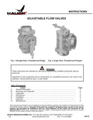
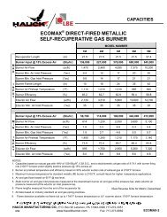
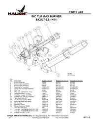
H. NATURAL GAS FUEL PIPING SYSTEMPage 13SJ -9WARNINGIt is important to remove the high velocity oil sleeveand install the low velocity gas sleeve in the 075 –750 model burners when firing natural gas.NOTE<strong>Hauck</strong> recommends the use of gas manifoldsthat meet NFPA guidelines. NFPA requirestwo safety shutoff valves wired in series, ashutoff valve downstream of the second(blocking) shutoff valve, and high and low gaspressure switches that are interlocked withthe burner’s safety shutoff valves. <strong>Hauck</strong> gasmanifolds have been designed to ensurecompliance to NFPA requirements.1. Install a controlling gas regulator in the main gas line within 25 ft (7.6m) of the burner. Foroptimum control, supply 15-25 psig (103 – 172 kPa) to this regulator. This regulator shouldbe sized to provide the required gas flow at the inlet of the burner manifold; 2 - 5 psig(14 - 35 kPa) is a nominal expected gas pressure. Exact gas pressures will be set at start-up.2. A manual equipment isolation valve, sediment trap and gas strainer must be installedupstream of the gas control regulator to ensure compliance to NFPA requirements. Themanual equipment isolation valve facilitates servicing of the gas control regulator, sedimenttrap, strainer, and sediment trap, strainer, and other components in the gas manifold.3. The gas company should purge the main gas line to remove scale and dirt before it isattached to the burner gas manifold.4. Connect the main gas line (see Figure 8).IMPORTANTInstall a flexible fitting in the gas manifold to reduce flexing of the manifold resultingfrom plant vibrations. Be sure to install the gas metering orifice section (seeFigure 9) provided with the gas valve metering kit to measure gas flow.Excluding the gas metering orifice section will make initial setup and tuningdifficult.
Page 14SJ -9Y4220(NOT TO SCALE)Figure 8. Typical Schematic of Burner Gas ManifoldX4845(NOT TO SCALE)Figure 9. Dimensions for Gas Metering Orifice
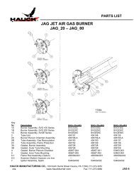
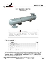
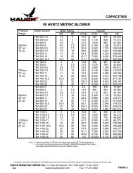
5. The piping from the gas regulator outlet to the burner gas manifold should be sized tominimize pressure losses.6. Check blower rotation. The impeller should rotate toward the blower discharge.7. Inspect and operate the plant exhaust damper control. The exhaust damper should becapable of maintaining a consistent negative pressure at the drum front bulkhead ofnegative 0.2 to negative 0.5 "wc (negative 5 to negative 13mm wc) from low to high firingrates for most applications.8. Install a gas sampling probe in the dryer rear plate (see Application Sheet GJ73).9. Set the low gas pressure switch to an initial setting of 0.5 psig (3.4 kPa).10. Set the high gas pressure switch to an initial setting of 5 psig (34.5 kPa).Page 15SJ -911. Complete the initial adjustment of the gas butterfly valve as follows: The valve is factory setto travel 90 degrees from position 1 to position ‘Run’. This travel can be modified to increaseor decrease low fire by choosing a lower or higher starting point.12. Open all manual shutoff valves in the gas line upstream of the gas pressure switch.WARNINGAdjustment of this equipment and its components byunqualified personnel can result in fire, explosion, severepersonal injury, or even death.13. Start gas flow to the gas manifold.14. Adjust the gas regulator until the pressure gauge upstream of the main gas automatic shutoffvalves indicates a pressure of 2 psig (13.8 k Pa).15. High fire can be modified by increasing or decreasing gas pressure. After setting high firegas pressure, low fire must be rechecked. Refer to individual Burner Gas Orifice MetersGraph for gas flows through the gas orifice meter (see Figure 10).16. Burner flame adjustment spin vanes can be set at 0 to 60 degrees; 0 degrees narrows theflame, 60 degrees widens the flame, and 30 degrees is a nominal starting point.17. Burner air adjustments: (see Section P).18. Recheck all linkages for tightness.19. Install a U-tube manometer across the gas orifice meter taps.20. Connect a gas analyzer to the gas sampling probe.21. Exhaust gas readings should be taken with the burner firing at operating tonnage(see Application Sheet GJ73).
Page 16SJ -9Q753Figure 10. Gas Orifice Meters Graph
I. LIGHT FUEL OIL PIPING SYSTEMPage 17SJ -9WARNINGAdjustment of this equipment and its components byunqualified personnel can result in fire, explosion,severe personal injury, or even death.NOTE<strong>Hauck</strong> requires the use of oil manifolds that meetNFPA guidelines. NFPA requires two safetyshutoff valves piped in series in the burner’s mainoil line. A low/high oil pressure switch must beinterlocked with the burner’s safety shutoff valves.1. Light fuel oil supply manifold (see Figure 11 and 12): For recommended piping sizes,see Table 3. For POM oil manifold installation instructions, see Section G.Table 3. Minimum Pipe Size for <strong>Hauck</strong> Oil Supply Pumping Units
Page 18SJ -92. Before attaching fuel oil lines, purge the piping to remove scale and dirt that could clog anddamage oil equipment.3. Open all shutoff valves upstream of the fuel oil metering valve(s).4. Be sure that the metering valve(s) is in the low fire position.5. Open the mini-ball valve to the pressure gauge.6. Slowly adjust the bypass relief valve until the initial set-up fuel oil pressure is achieved (seeTable 4). Final pump pressure will have to be adjusted to attain desired burner output andstack exhaust gas analysis.StarJetModel No.Fuel Oil Pressurew/36 osig (15.5 kPa) Blower075 45 psig (310 kPa)150 50 psig (345 kPa)200 45 psig (310 kPa)260 50 psig (345 kPa)360 50 psig (345 kPa)520 50 psig (345 kPa)580 80 psig (550 kPa)750 70 psig (485 kPa)980 80 psig (550 kPa)Table 4. Fuel Oil Pressures7. Check rotation of the combustion blower. The impeller should rotate toward the blowerdischarge.8. Inspect and operate the plant exhaust damper control. The exhaust damper should becapable of maintaining a consistent negative pressure at the drum front bulkhead ofnegative 0.2 to negative 0.5 "wc (negative 5 to negative 13mm wc) from low to high firingrates for most applications.9. The low/high oil pressure switch is factory set at a low set point of 15 psig (103 kPa) and ahigh set point of 80 psig (552 kPa). Set point adjustments may be required depending on theburner and fuel oil piping specifics.10. Inspect the complete fuel oil system for leaks. Repair as necessary.11. The burner oil metering valve is factory set to travel 90 degrees from position 1 to 10.12. The low fire oil valve is manually set and regulates low fire flow. This valve can easily bechanged to regulate low fire oil flow. Start this valve at position 9. The low fire valve caneasily be cleaned:a. Mark the valve pointer position.b. Turn the valve counterclockwise to the ’clean’ position.c. Return the valve pointer to its original position.
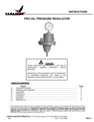
13. High fire oil flow can be adjusted by increasing or decreasing fuel oil pressure. Afterchanging fuel oil pressure, low fire flow should be rechecked. Low and high fire rates ingal/min or liters/min can be checked and recorded with the in-line oil flow meter providedwith the prepiped oil manifold.Page 19SJ -914. Burner flame spin vane adjustment can be set at 0 to 60 degrees. 0 degrees narrows theflame, 60 degrees widens the flame, and 30 degrees is a nominal starting point.15. Burner air adjustments: (see Section P).16. Recheck all linkages for tightness.17. Connect a gas analyzer to the gas sampling probe (see Application Sheet GJ73). Exhaustgas readings should be taken at operating tonnage.X6263(NOT TO SCALE)Figure 11. Typical Schematic of Burner Light Fuel Oil Piping
Page 20SJ -9NOTEOil manifold must bemounted in a horizontalposition. Mount as closeto the burner as possible.Mount manifold belowthe burner’s center-line.X6189(NOT TO SCALE)J. HEAVY FUEL OIL PIPING SYSTEMFigure 12. POM Prepiped Oil Manifold DetailWARNINGAdjustment of this equipment and its components byunqualified personnel can result in fire, explosion,severe personal injury, or even death.Heated fuel oil and piping is hot. Precautions must betaken to prevent contact with heated oil and piping.Proper insulation should be installed on hot oil pipes.Protective gloves and clothing are recommended whenworking with heated fuel oil.IMPORTANTFor all heavy fuel oil applications, i.e., any oil requiring heating for use,oil piping must be heat traced (electric or steam) and insulated.Self-regulating heat tracing is recommended to maintain the desiredtemperature of a given fuel oil to achieve 90 SSU (1.8 x 10 -5 m 2 /sec)or less at the burner. Electrical heat tracing with a nominal rating of12W/ft (39W/m) covered with a nominal 2" (50mm) fiberglass typeinsulation is sufficient for most applications.
Page 21SJ -9NOTE<strong>Hauck</strong> recommends the use of oil manifolds that meet NFPAguidelines. NFPA requires two safety shutoff valves piped in series inthe burner's main oil line. A low/high oil pressure switch must beinterlocked with the burner's safety shutoff valves. When preheated oilis used, a low/high oil temperature limit switch must be interlocked tothe burner's oil safety shutoff valves. <strong>Hauck</strong>'s oil manifolds have beendesigned to ensure compliance to NFPA requirements.1. Heavy fuel oil supply piping and manifold (see Figure 13 and 14): For recommended pipingsizes, see Table 4. For POM-H oil manifold installation instructions, see Section G.2. Fuel oil used must be 90 SSU (1.8 x 10 -5 m 2 /sec) or less for proper atomization andburning. Use a <strong>Hauck</strong> viscometer kit (order separately – Part No. 36931) to determine theproper oil temperature for 90 SSU.3. Set the fuel oil heater temperature set point and the indicating low oil temperature switch(located on the burner's oil manifold) to the temperature determined from Step 2.4. Before attaching fuel oil lines, purge the piping to remove scale and dirt that could clog anddamage oil equipment.5. Open all shutoff valves upstream of the fuel oil metering valve(s).6. Open the mini-ball valve to the pressure gauge.7. Start the pump and heating medium.8. Close the manual ball valve immediately downstream of the normally open solenoid in theheavy oil recirculating line.9. Adjust the bypass relief valve on the pump set until the initial set-up oil pressure is achieved(see Table 4). Final pump pressure will have to be adjusted to attain desired burner outputand stack exhaust gas analysis.10. Open the manual ball valve in the heavy oil recirculating line.11. Using the low/high oil temperature indicating switch located on the burner, verify that the fueloil is at the desired temperature from Step 2. Adjust the heater until the proper fuel oiltemperature is attained at the burner.12. Check and repair all fuel oil leaks.13. The burner oil metering valve is factory set to travel 90 degrees from position 1 to 10.14. The low fire oil valve is manually set and regulates low fire flow. This valve can easily bechanged to regulate low fire. Start this valve at position 9. The low fire valve can easily becleaned:a. Mark the valve pointer position.b. Turn the valve counterclockwise to the 'clean' position.c. Return the valve pointer to its original position.
15. High fire can be modified by increasing or decreasing fuel oil pressure or by changingthe maximum oil metering valve stroke. After changing fuel oil pressure, low fire shouldbe rechecked.16. Check rotation of the combustion blower. The impeller should rotate toward the blowerdischarge.17. Inspect and operate the plant exhaust damper control. The exhaust damper should becapable of maintaining a consistent negative pressure at the drum front bulkhead ofnegative 0.2 to negative 0.5 "wc (negative 5 to negative 13mm wc) from low to high firingrates for most applications.18. The low/high oil pressure switch is factory set at a low set point of 15 psig (103 kPa) anda high set point of 80 psig (552 kPa). Set point adjustments may be required dependingon the burner and fuel oil piping specifics.19. Burner flame spin vanes adjustment can be set at 0 to 60 degrees; 0 degrees narrowsthe flame, 60 degrees widens the flame, and 30 degrees is a nominal starting point.20. Burner air adjustments: (see Section P).21. Recheck all linkages for tightness.22. Install a gas sampling probe in the dryer drum rear (see Application Sheet GJ73).23. Connect a gas analyzer to the gas sampling probe (see Application Sheet GJ73).Exhaust gas readings should be taken at operating tonnage.Page 22SJ -9
Page 23SJ -9Y7513(NOT TO SCALE)Figure 13. Typical Schematic of Burner Heavy Fuel Oil Piping
Page 24SJ -9NOTEOil manifold must bemounted in a horizontalposition. Mount as closeto the burner as possible.Mount manifold belowthe burner’s center-line.X6210(NOT TO SCALE)Figure 14. POM-H Prepiped Heavy Oil Manifold DetailK. HEAVY OIL INSERT HEATERHeavy, waste, or recycled fuel oils require some means of viscosity control. The <strong>Hauck</strong> Heavy OilInsert Heater installed in the burner nozzle supply line is a perfect solution to the viscosity controlproblem and reliable main flame ignition of the burner at cold temperatures. The heavy oil insertheating element, in conjunction with the oil temperature indicating controller, will maintain anoptimum oil temperature in the oil tube to ensure a reliable burner main flame ignition after anextended shutdown of the burner.W7655(NOT TO SCALE)Figure 15. Heavy Oil Insert Heater
Page 25SJ -9NOTE120V/60Hz power for the heavy oil insert heatermust be supplied separately by the customerand wired into the heater junction box.Operation of the heavy oil insert kit is as follows (see Figure 15):1. Adjust the low temperature controller to the desired temperature as determined in Section Kfrom testing of the heavy oil viscosity.NOTEAdjusting the trip setpoint above the required temperature, asdetermined by fuel oil viscosity testing, may result in coking ofthe fuel oil in the insert oil piping.2. Energize the insert heater circuit breaker switch.3. When the oil temperature exceeds the setpoint on the oil temperature indicating controller, theoil temperature indicating controller switch contact will open and power to the heater elementis removed.4. When the oil temperature drops below the setpoint on the oil temperature indicating controller,the oil temperature indicating controller switch contact will close and the heater element willenergize.See SJ-9.2 StarJetHeavy Oil Insert Heater Kit Instructions for more specific detail on theoperation and maintenance of the heavy oil insert heater.
Page 26SJ -9L. FUEL OIL NOZZLE ADJUSTMENTThe position of the fuel oil nozzle affects its ability to atomize the oil. The low pressure nozzle orcompressed air nozzle should be positioned as shown in Figure 16.To change the fuel oil nozzle position:Figure 16. Oil Nozzle Position1. Shut the oil valve upstream of the safety shutoff valves.2. Disconnect the burner oil insert assembly from the oil valve manifold, using the union locateddownstream of the flexible hose.3. Note the present orientation of the nozzle while assembled in the burner. Determine if thenozzle must be retracted into or extended out of the primary air tube (see Figure 16).4. Remove the four bolts securing the backplate to the burner.5. Loosen the jam nut on the backplate of the burner oil insert assembly.6. Rotate the backplate to effect the required retraction or extension of the nozzle. One fullrotation of the backplate will move the nozzle approximately 0.1" (2.5mm).7. Once the proper positioning of the nozzle is completed:a. Tighten the jam nut.b. Attach the burner oil insert assembly to the oil valve manifold, using theunion provided.c. Open the oil valve upstream of the safety shutoff valves.X7639(NOT TO SCALE)
Page 27SJ -9M. COMPRESSED AIR/OIL SYSTEMThe <strong>Hauck</strong> high pressure oil nozzle is designed to finely atomize No. 2 fuel oil and cleanpreheated No. 4, No. 5 and No. 6 fuel oil. Oil viscosity should be 90 SSU (1.8 x 10 -5 m 2 /sec) orless. Preheat fuel oil and heat trace piping when using No. 4, No. 5, and No. 6 fuel oil to achieve90 SSU oil at the burner (see Compressed Air/Oil Adjustment).Care should be taken to insure that the air and oil supplied to the burner are free of dirt particlesand water. Purge oil and air lines before connecting them to the compressed air/oil insert. Thenozzle should be inspected and cleaned before the start of each session and possibly moredepending on the cleanliness of the air and fuel.COMPRESSED AIR PIPING1. The compressed air supply line must be of adequate size (see Table 5) and be a dedicatedline from the compressor to the burner compressed air inlet. For longer piping runs than thoselisted in the table, increase the hose by one pipe size. Before attaching lines, purge the hoseto remove any dirt that could clog and damage the oil nozzle.StarJetModel No.Min. HoseSizeMax. HoseLength150 - 260 3/4 NPT (DN 20) 70 ft (21 m)360 - 580 1 NPT (DN 25) 160 ft (49 m)750 - 980 1 NPT (DN 25) 90 ft (27 m)Table 5. Flexible Air Hose Size Requirements2. Compressed air requirements are listed in Table 6. Compressed air must be supplied to theinlet of the compressed air manifold at a minimum of 90 psig (620 kPa). The compressed airregulator modulates the compressed air flow as oil flow is modulated to reduce compressed airconsumption at lower firing rates.NOTEThe compressed air low supply pressure switchand low atomizing pressure switch must both beinterlocked with the burner’s oil safety shutoffvalves.The compressed air solenoid valve is normallywired in parallel with the burner’s safety shutoffvalves.Reference the control panel drawings for wireand/or terminal numbers.
Page 28SJ -9StarJetModel No.150200260360520580750980Oil PressureTo BurnerNozzleCompressedAir Pressureto BurnerNozzleFiringRate Oil FlowCompressedAir Flow(gpm) (lpm) (psig) (kPa) (scfm) (nm 3 /min) (psig) (kPa)High Fire 3.4 12.9 32 220 45 1.2 33 22850% 1.7 6.4 14 97 40 1.1 16 11025% 0.84 3.2 8 55 40 1.1 10 69Low Fire 0.5 1.9 6 41 35 0.9 8 55High Fire 4.9 18.5 45 310 45 1.2 45 31050% 2.4 9.1 32 221 45 1.2 32 22125% 1.2 4.5 12 83 40 1.1 12 83Low Fire 0.7 2.6 7 48 40 1.1 8 55High Fire 5.9 22.3 45 310 45 1.2 45 31050% 3.0 11.4 32 221 45 1.2 32 22125% 1.5 5.8 12 83 40 1.1 12 83Low Fire 0.85 3.2 7 48 40 1.1 8 55High Fire 9.1 34.4 60 414 65 1.7 58 40050% 4.6 17.4 48 331 65 1.7 44 30425% 2.3 8.7 36 248 60 1.6 30 207Low Fire 1.5 5.7 30 207 55 1.5 20 138High Fire 11.7 44.3 60 414 65 1.7 58 40050% 5.8 22.0 50 345 65 1.7 44 30425% 2.9 11.0 38 262 60 1.6 30 207Low Fire 1.5 5.7 30 207 55 1.5 20 138High Fire 14.5 54.9 52 359 90 2.4 43 29650% 7.2 27.3 30 207 83 2.2 25 17225% 3.6 13.6 22 152 81 2.2 20 138Low Fire 2.0 7.7 21 145 79 2.1 19 131High Fire 18.1 68.5 54 372 115 3.1 40 27650% 9.1 34.4 34 234 110 2.9 25 17225% 4.5 17.0 28 193 100 2.7 20 138Low Fire 2.0 7.6 20 138 100 2.7 12 83High Fire 24 90.8 66 455 118 3.2 48 33150% 12 45.4 40 276 112 3.0 30 20725% 6.5 24.6 30 207 106 2.8 22 152Low Fire 3.0 11.4 22 152 100 2.7 14 97Table 6. Compressed Air and Oil Requirements
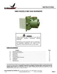
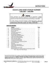
Page 29SJ -9COMPRESSED AIR/OIL ADJUSTMENT1. Air and fuel flows and pressures can be observed at the burner using the compressed airand fuel flow meters and corresponding pressure gauges (see Figure 17).2. Compressed air supply pressure to the inlet of the compressed air manifold must be 90 psig(620 kPa) or greater. The supply pressure is measured via the gauge on the inlet to thecompressed air flow meter (see Figure 17). The compressed air low supply pressure switch ispreset at 60 psig (414 kPa). Set point adjustment may be required depending on the burnerand compressed air piping specifics.Figure 17. Compressed Air Manifold DetailX7303(NOT TO SCALE)3. For the compressed air manifold to function properly, the impulse line and upper chamber ofthe pressure reducing regulator must be loaded with oil by opening the vent valve on theregulator until oil vents, then closing the vent valve.4. Final compressed air flow and pressure adjustment is made via the compressed air trimvalve (see Figure 17). With the burner at high fire, adjust the trim valve until the compressedair burner inlet pressure gauge, located downstream of the trim valve, reads approximately60 psig (414 kPa). The compressed air low atomizing air switch is preset at 5 psig (34.5 kPa).Set point adjustment may be required depending on the burner and compressed air pipingspecifics.5. Compressed air flow can be read directly from the compressed air flow meter. Refer toCompressed Air Flow Meter section and Figure 19 for detailed instructions on how to readthe compressed air flow meter. Verify that both the compressed air flow and burner inletpressure, from step 4, meet or exceed the values given in Table 6 and/or the additionalburner capacity and performance data sheets.
Page 30SJ -9IMPORTANTFor all heavy fuel oil applications, i.e., any oil requiring heating for use,oil piping must be heat traced (electric or steam) and insulated.Self-regulating heat tracing is recommended to maintain the desiredtemperature of a given fuel oil to achieve 90 SSU (1.8 x 10 -5 m 2 /sec)or less at the burner. Electrical heat tracing with a nominal rating of12W/ft (39W/m) covered with a nominal 2" (50mm) fiberglass typeinsulation is sufficient for most applications.W7346(NOT TO SCALE)Figure 18. Compressed Air/Oil Insert AssemblyThe compressed air insert assembly is inserted in the primary air tube. Tighten the rear flangebolts. The nozzle can be adjusted to maintain the 1/16" (1.6mm) dimension shown in Figure 18.COMPRESSED AIR FLOW METERThe compressed air flow meter is offered with a standard multi-pressure flow scale.The multi-pressure flow scale has a vertically graduated scale, calibrated for air in standard cubicfeet per minute (scfm) at 1.0 s.g. (70°F at 100 psig); also available in a metric version in liters persecond (lps) at 1.0 s.g. (21°C at 6.9 bar). The multi-pressure scale design allows for use at supplypressures from 40 - 130 psig in 10 psig increments (metric version from 3.0 - 9.0 bar in 1 barincrements).To determine the compressed air flow rate, refer to Figure 19 and proceed as follows:1. Read the inlet pressure on the pressure gauge of the compressed air flow meter.2. Select the appropriate inlet pressure (psig) vertical line, or interpolated value closest to thegauge reading, and follow the line upward until it intersects the brightly colored horizontalindicator bar.3. From the intersecting point on the horizontal indicator bar, follow the slope as shown onthe diagonal lines to the 100 psig inlet pressure vertical line and interpolate the scfm orlps flow rate (Note for the example shown in Figure 19, with an inlet pressure of 60 psig,the compressed air flow rate is approximately 40 scfm).
N. LIQUID PROPANE (LP) FUEL PIPING SYSTEMPage 32SJ -9WARNINGAdjustment of this equipment and its components by unqualified personnel canresult in fire, explosion, severe personal injury, or even death.LP is highly flammable and heavier than air. It will accumulate near the ground inthe area of a leak and will dissipate relatively slowly. LP or Butane in its liquid statecan cause freezing and severe injury.<strong>Hauck</strong> does not recommend installation of a line-reducing regulator in the LPsupply line. If the regulator diaphragm were to total system pressure would beapplied to the burner and could result in damage to equipment, including thebaghouse, and result in serious injury to personnel.NOTE<strong>Hauck</strong> recommends the use of LP manifolds that meet NFPA guidelines. NFPArequires two safety shutoff valves piped in series in the burner's main LP line. Alow/high pressure LP switch must be interlocked with the burner's safety shutoffvalves. <strong>Hauck</strong>'s LP manifolds have been designed to ensure compliance to NFPArequirements. All piping must be installed in compliance with applicable pipingcodes and regulations. Equipment must meet the ratings for service as indicated inNFPA 58.1. Before attaching LP fuel lines, purge the lines with compressed air. Then, leak test piping withcompressed air.2. Connect the main LP line at the appropriate connection on the burner skid. The capacity ofthe LP fuel system should be 1.5 times the rated capacity of the burner.3. If <strong>Hauck</strong> has supplied the LP pump set for this application, consult the pump installationinstructions for information on this unit, taking special care to avoid upward loops and anyother conditions that may trap vapor.
Page 33SJ -9Y4059NOT TO SCALE)Figure 20. Typical Schematic of LP Piping
Page 34SJ -9NOTELP manifold must bemounted in a horizontalposition. Mount as closeto the burner as possible.Mount manifold belowthe burner’s center-line.X6190(NOT TO SCALE)Figure 21. PLPM Prepiped LP Manifold DetailWARNING<strong>Hauck</strong> does not recommend installation of a line-reducingregulator in the LP supply line. If the regulator diaphragmwere to rupture, total system pressure would be applied to theburner and could result in damage to equipment, including thebaghouse, and result in serious injury to personnel.CAUTION<strong>Hauck</strong> strongly recommends that a bypass flowcontrol valve and a backpressure regulator (availablefrom <strong>Hauck</strong>) be installed in all LP systems and pipedas shown in Figure 20.4. Close the manual ball valve upstream of the PLPM manifold (see Figure 21).5. Open the manual shutoff valve on the inlet side of the pump.6. Turn on the LP pump to start LP flow.7. Check all LP lines and connections for leaks following accepted standards and practices.8. Open the manual ball valve upstream of the PLPM manifold and check the manifold forleaks (see Figure 21). After burner has been ignited and LP is flowing to the burner nozzle,check all piping for leaks.
Page 35SJ -9WARNINGFrost or icing is an indication of an LP leak. Itis possible for a leak to occur without suchevidence. Although the LP supply is initially ina liquid state, as it is vaporized it becomesheavier than air and accumulates near theground and dissipates relatively slowly,becoming highly flammable. Extreme careshould be exercised with LP fuels andsystems.NOTEThe system shown in Figure 20 is designed foroptimum performance at ambient air temperaturesabove 40°F (5°C). For operation at temperaturesbelow 40°F, consult <strong>Hauck</strong> for recommendations.9. Adjustment of LP supply pressure:a. Install an amp probe on the LP pump power supply line.CAUTIONDo not exceed the maximum LP pump motornameplate amp load at any time while makingadjustments.b. Close the ball valve between the backpressure regulator and the tankto temporarily take the regulator out of the system (see Figure 20).c. Adjust the bypass flow control valve to the following initial settings:100% Commercial Propane 235 psig (1620 kPa)50/50 Propane/Butane 170 psig (1170 kPa)100% Butane 95 psig (655 kPa)NOTEIf pump motor nameplate amperage is exceeded, reducepressure in Step 9.c to below nameplate amp rating.d. Reopen the bypass flow control valve closed in Step c.
Page 36SJ -9e. Adjust the backpressure regulator to the following initial settings:100% Commercial Propane 210 psig (1450 kPa)50/50 Propane/Butane 145 psig (1000 kPa)100% Butane 70 psig (480 kPa)NOTEIf motor amperage in Step 9.c exceeded nameplate amprating, set backpressure regulator at 25 psig (172 kPa) lessthan the bypass flow control valve setting.These settings are initial settings only. Settings are basedon 60°F (15.5°C) fuel temperature plus normal pumppressure; pump differential pressure = 100 psig (700 kPa).Settings will have to be readjusted for changes intemperature and operation. The bypass flow control valveshould always be set approximately 25 psig (172 kPa)above the backpressure regulator to insure pumpprotection.10. a. Be sure the LP metering valve is in the low fire position. This valve is factory set to travelapproximately 90 degrees starting at position 1 to 10. These positions can be modified toadjust to a higher or lower firing rate. If adjusting high fire, low fire must be reset.b. Read and record LP metering valve settings and flow rates using the in-line LP flowmeter (gal/min or liters/min LP liquid) provided with the burner.11. Check rotation of the combustion blower. The impeller should rotate toward the blowerdischarge.12. Inspect and operate the plant exhaust damper control. The exhaust damper should becapable of maintaining a consistent negative pressure at the drum front bulkhead ofnegative 0.2 "wc to negative 0.5 "wc ( negative 5 to negative 13mm wc) from low to highfiring rates for most applications.13. The low/high LP pressure switch is factory set at a low set point of 165 psig (1140 kPa)and a high set point of 230 psig (1590 kPa). Set point adjustments may be requireddepending on the burner and LP piping specifics.14. Burner flame spin vanes adjustment can be set at 0 to 60 degrees; 0 degrees narrowsthe flame, 60 degrees widens the flame, and 30 degrees is a nominal starting point.15. Burner air adjustments: (see Section P).16. Install a gas sampling probe in the dryer drum rear (see Application Sheet GJ73).17. Connect a gas analyzer to the gas sampling probe (see Application Sheet GJ73). Exhaustgas readings should be taken at operating tonnage.
Page 37SJ -9NOTEDifferent nozzles are required when burningliquid propane, butane, or a mixture of propane/butane. Consult <strong>Hauck</strong> for your specific fuelnozzle requirements.WARNINGDo not attempt to reposition the LP nozzlewhile the burner is firing. Considerablepressure exists under firing conditions.Attempting to adjust the LP nozzle while theburner is firing may result in equipment damageor injury to personnel.Figure 22. LP Nozzle PositionX7639(NOT TO SCALE)To change the LP nozzle position:1. Shut the LP manual ball valve upstream of the LP safety shutoff valves.2. Disconnect the burner LP insert assembly from the LP valve manifold, using theunion located downstream of the flexible hose.3. Note the present orientation of the LP nozzle while assembled in the burner. Determine if thenozzle must be retracted into or extended out of the primary tube (see Figure 22).
Page 38SJ -94. Remove the four bolts securing the backplate to the burner.5. Loosen the jam nut on the backplate of the burner LP insert assembly.6. Rotate the backplate to effect the required retraction or extension of the nozzle. One fullrotation of the backplate will move the nozzle approximately 0.1" (2.5mm).7. Once the proper positioning of the nozzle is completed:a. Tighten the jam nut.b. Attach the burner LP insert assembly to the LP valve manifold, using the unionprovided.c. Open the LP valve upstream of the safety shutoff valves.
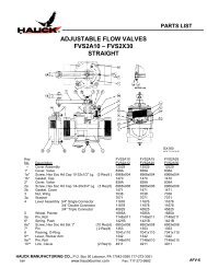
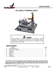
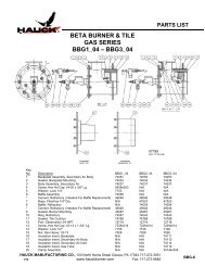
Figure 23. Vapor Pressures of Propane, Butane & Butane-Propane MixturesPage 39SJ -9
Page 40SJ -9O. <strong>BURNER</strong> PILOT SYSTEMThe StarJet Burner incorporates an air inspirited via gas (AIG) pilot system (see Figure 24). Thepilot and UV scanners should always be oriented to point downward. As delivered, the pilot andUV scanners should be properly oriented, based on the air inlet orientation specified when theburner was ordered. Adjustment and operation of the pilot system is detailed below.1. Before connecting to the pilot, the gas line should be purged to remove any dirt. Connect thepilot gas supply line to the inlet of the pilot gas shutoff valve. Size the pilot gas supply line toavoid excessive pressure drops. For pilot gas supply lines up to 25 ft (7.6m), use 1/2 NPT(DN 15) or larger piping.2. Constant gas pressures ranging from 15 psig (103 kPa) minimum to 25 psig (172 kPa)maximum must be available at the inlet of the <strong>Hauck</strong> gas pilot manifold. Pilot capacity shouldnot exceed 150,000 Btu/hr (44kW).Y4061(NOT TO SCALE)Figure 24. Pilot Manifold Detail3. The spark wire gap is factory set at 1/8" (3 mm). This gap can be changed by carefullyremoving the pilot internals. Bend the spark wire to adjust, reinsert, and check the gap.For field adjustments, a U.S. 5¢ coin with 0.08" (2 mm) thickness can be used as a gaugefor adjusting the spark gap.4. Complete the initial pilot adjustment of the air shutter as follows (see Figure 25):a. Loosen, but do not remove, the locking thumbscrew.b. Adjust the air shutter to approximately 1/4" (6.4mm) gap opening.c. Securely tighten the locking thumbscrew.d. Slowly open the gas flow valve and light the pilot by means ofelectric ignition.
Page 41SJ -9W7404(NOT TO SCALE)Figure 25. Pilot AIG InspiratorW7403(NOT TO SCALE)Figure 26. Pilot Scanner & AdapterP. OPERATIONWARNINGAdjustment of this equipment and its components byunqualified personnel can result in fire, explosion, severepersonal injury, or even death.1. The StarJet air/fuel system uses a single control motor for modulation of burner air and fuel.This control motor travels 90° from low to high fire, driving both the burner air and fuel valvessimultaneously.2. Only 40% of total required burner air is passed through the burner; this includes burnerprimary air which is on at all times on all fuels, and secondary air. The remaining air forcombustion is pulled past the burner cone by the plant exhaust system.
Page 42SJ -93. The plant exhaust fan must be running with it’s damper open sufficiently for the proper purgetime. The minimum purge time is the time required for four volumes of air to flow through theentire combustion and exhaust system (including the baghouse and exhaust stack).4. A constant negative 0.25"wc (6.3mm wc) draft is important in maintaining a constant air flowpast the burner without puffing the drum front. This negative pressure can easily bemaintained with a <strong>Hauck</strong> DPS digital pressure control system. The negative pressure tapshould be located on the drum front bulkhead between the burner and the O.D. of the drum atthe burner centerline.5. Prior to light off, ensure that the secondary air low fire limit switch (see Figure 27) is set so theswitch contacts are closed (engaged) by the bottom of the pointer. When the burner ispositioned above low fire, the switch contacts should open. Consult control panel instructionsfor wire and/or terminal numbers.6. Ensure that the low fire fuel limit switches, located on the respective fuel manifolds, are setto have closed contacts when the fuel valve is at low fire.7. Initial burner component settings for all fuels are presented in Table 7 and 8, and should beverified prior to burner light off.8. When making any adjustments to the burner, exhaust gas measurements should be takento verify that complete combustion is taking place (see Application Sheet GJ73 for generalinformation on conducting exhaust gas analysis).S4021(NOT TO SCALE)Figure 27. Low Fire Limit Switch
Table 7. Initial Burner Component Settings for Natural Gas & LPPage 43SJ -9
Table 8. Initial Burner Component Settings for OilPage 44SJ -9
Page 45SJ -9Q. FLAME SHAPE ADJUSTMENTSThere are two devices on the burner which can affect the flame shape: the spin vane adjustmentring and the secondary air sleeve. The spin vane adjustment ring is the principle means ofadjusting flame shape.The spin vane adjustment ring uniformly adjusts the angle of the secondary air spin vanes whichimpart spin to the secondary air stream as it leaves the burner. These vanes, when set at anangle, increase the air/fuel mixing rate and produce a shorter, bushier flame. The effect can beminor or severe, depending on the angle setting of the vanes. The greater the angle (adjustablefrom 0-60 degrees), the shorter and bushier the flame. The amount of secondary spin is read onthe spin vane indicator, mounted on the spin vane setting indicator plate. In some applications,high spin may cause overheating of the drum front bulkhead and combustion zone flights. In suchcases, reduce the spin angle as necessary until such condition is eliminated.Spin Vane Adjustment:1. Shut down the burner system.2. Loosen the locking bolt and using the spin vane adjusting lever, rotatethe ring until the spin vane indicator reads 30 degrees.3. Tighten the locking bolt.Burners Equipped With Secondary Air Sleeve:The secondary air sleeve prevents the free expansion of the secondary air as it leaves thesecondary air tube. This concentrates the secondary air, which improves the atomization offuel oil. The farther the sleeve is extended, the narrower the flame becomes. Typically, the sleeveshould not be extended more than 3/4" (19 mm). The optimal sleeve position is dependent on thespecific fuel used and is more critical with heavy oil. If the sleeve is not extended far enough, theoil may not be atomized fully and cause a dark flame. On heavy oil, if the sleeve is extended toofar, the atomized oil spray will impinge and deposit on the sleeve. Refer to the start-up settings,Tables 8 and 9, for nominal sleeve settings.WARNINGThe HIGH VELOCITY secondary air sleeve is for use with:OIL FIRING MODEL 075 – 750LP FIRING SJ150GAS FIRING NOT USED WITHGAS FIRING ON ANY<strong>BURNER</strong> MODELIf your application requires a HIGH VELOCITY SLEEVE for oilfiring, be sure to remove the HIGH VELOCITY SLEEVE fornatural gas firing. If you are unsure which model sleeve isinstalled on your burner, consult <strong>Hauck</strong>.
Page 46SJ -9Secondary Air Sleeve Adjustment:1. Shut down the burner system.2. Allow the burner to cool to the touch.3. In the front of the burner is a slot (see Figure 28) to adjust the sleeve:a. Loosen the sleeve locking bolt.b. Relocate the sleeve to the desired extension distance (Refer to Table 7 or 8 for nominalsleeve extensions). The extension distance is the distance the sleeve is extending out theend of the burner secondary air tube (see Figure 28).c. Tighten the sleeve locking bolt.Y7405(NOT TO SCALE)Figure 28. Secondary Air Sleeve Adjustmentand Spin Vane Adjusting RingR. FLAME HOLDER CONE ADJUSTMENTThe flame holder cone assists in the stabilization of the StarJet’s flame. Normally, the coneshould be positioned so that it is completely retracted (as far towards the burner as possible). Thecone should also be set square with the burner. To adjust the position of the flame holder cone:1. Loosen the four flame holder locking bolts.2. Position the flame holder cone. Normal position is fully retracted in the adjustment range.3. Place a straight edge horizontally across the flame holder cone.4. Measure the distance from the straight edge to the front of the burner on both the left andright sides. Adjust the cone to get the same measurement on both sides.
5. Tighten the flame holder locking bolt on both the left and right sides.Page 47SJ -96. Place the straight edge vertically on the flame holder cone.7. Adjust the cone to get the same measurement on both the top and bottom.8. Tighten the flame holder locking bolt on the top and bottom.S. MAINTENANCEThe <strong>Hauck</strong> StarJet Burner has minimal internal moving parts and is relatively maintenance free.However, there are a few items that should be periodically checked.1. Check the burner secondary air damper, fuel control valves, and their associated linkage forproper operation.2. Check and lubricate all points of valve linkage. Mark linkage so any slippage will be detectedand corrected.3. Grease fittings located on the secondary air damper bearings should be checked andlubricated once a month.4. For burners fired on oil:Dirt can clog the atomizing air nozzle, as well as cause problems firing the burner. If thenozzle is dirty, fuel oil will not atomize properly and will result in lower combustion efficiency.Twice a year (or more frequently when firing heavy oil, recycled oil, or in very dustyconditions), remove and clean the burner oil insert tube and nozzle assembly as describedbelow:a. Shut off the oil flow to the burner.b. Note the relative location of the nozzle with respect to the primary air tube.c. Remove the bolts, which secure the burner backplate to the burner body.d. Remove the burner backplate with its attached oil insert tube and nozzle.e. Disassemble the nozzle. Clean all of the components of oil and other foreign materialthat may be plugging the nozzle holes. If used with heavy oil, remove the nozzle and soakin a suitable solvent to loosen any oil deposits. Scrape the nozzle body and holes (if necessary)using wooden tools or a plastic bristle brush only, being careful not todamaged machined parts.f. Reassemble the oil nozzle assembly and torque the center bolt to 30 inch-lbs (3.4 N-m).g. Reattach oil nozzle to primary air tube.h. Reattach the burner backplate to the burner body.i. Check to make sure the oil nozzle is at the proper position inside the burner (see Section L)
5. Periodically check all safety equipment, such as pressure switches, solenoid valves, andfuel safety shutoff valves, to make sure they are not clogged with dirt, or in any wayinoperative.Page 48SJ -96. Check and clean UV scanner lenses as conditions dictate to keep them clean of dirt and dust.7. Periodically, check and clean the air openings around the burner front.8. To prevent vibration and misalignment, periodically check to make sure that the secondary airsleeve locking bolt, spin vane adjusting ring locking bolt, and flame holder cone locking boltsare tight.9. Periodically check air/fuel ratio to ensure that the burner is operating at peak efficiency.Exhaust gas analysis can be performed with most commercially available gas analyzers.T. RECOMMENDED SPARE PARTSITEM QTY PART NO. DESCRIPTION1 1 16847 Control Motor, Med. Torque (SJ 075-580 only)2 1 20627 Control Motor, High Torque (SJ 750-980 only)3 2 20579 UV Scanner4 1 20533 Low Fire Limit Switch w/Adjustable Lever5 1 84447832 Air Pressure Switch 12-60"wc (3 - 15 kPa)6 1 47783x Spark Igniter Assembly7 1 15773 Gas Pilot Solenoid ValveTable 9. Recommended Spare PartsNOTE: See respective StarJet Burner’s Parts List for correct "x value" for Spark IgniterAssembly.
APPLICATION SHEETGas analyses are used to indicate the air/fuel ratio and to indicate the degree of completenessof combustion. If the mixing is poor, an excess of air must be supplied so that every particle offuel will contact some air and burn. Unburned fuel is simply wasted since it does not contributeheat to the process.DRYER DRUM GAS ANALYSISFOR NATURAL GAS, OIL AND LPA critical step in every dryer drum gas analysis is the placement of the sample tube. The appli-cability of the readings depends directly on the location from which the sample is drawn. To giveyou an idea of the recommended placement, we have included a drawing in this section. Referto “Typical Sample Tube Installation for Dryer Drum Gas Analysis”.The procedures used to make an accurate gas analysis vary not only with the method employedbut also with the manufacturer of the equipment. In most instances good readings require thatthe manufacturers instructions be adhered to rigidly.Conditions to perform a good analysis.1. Use a reliable gas analyzer.2. Sample pipe must be installed in the dryer drum to eliminate reading stray O 2 , overheatedRAP, or overheated AC.3. Sample should be taken with average tonnage, moisture and firing rates.4. Allow at least 10 to 15 minutes running time at production rates before taking readings.5. Sample tubing from the sample pipe to the analyzer should be as short as possible. Tubingshould be approximately 1/4 inch (6.4 mm) I.D. rubber, plastic, or silicone.6. Gases should be sampled until instrument settles out, normally a few minutes depending onsample line size, length, and pump volume.<strong>HAUCK</strong> MANUFACTURING CO., P.O. Box 90 Lebanon, PA 17042-0090 717-272-305112/04 www.hauckburner.com Fax: 717-273-9882GJ73FE
Interpretation of Gas Readings.Page 2GJ73FEEXAMPLEAssuming a drum gas analysis is taken at production rates.Readings Taken: O 2 - 4%CO - 2000 PPMCombustibles - 2%Problem: 4% O 2 - is too lowCO - is too highCombustibles are too highSolution: Gradually reduce fuel flow or increase air flow while watching O 2 , CO, andcombustibles. Typically the following will occur – O 2 will increase, CO willdecrease, and combustibles will decrease. Reduce fuel until minimal amountof combustibles are present. Then reduce fuel by a small amount for a safetymargin.NOTE: Typically some CO and combustibles will always be present.Variables Affecting the Combustion Process.1. Poor atomization of fuel: Atomizer contamination with particulate. Air passages clogged.2. Poor oil: Oil laden with particulate and unburnables.3. Switching fuels: Light to heavy oils, LP to butane.4. Flame shape.5. Stray air: Poor drum seals, larger than necessary feed openings, draft to high.6. Inadequate combustion zone.7. Material veiling thru flame: Interrupts burning, creating high CO and high combustibles.8. Overheating RAP or AC.9. Contaminated material.
Page 3GJ73FEBATCH PLANTTYPICAL SAMPLE TUBE INSTALLATION FOR DRYER DRUM GAS ANALYSISW7406(NOT TO SCALE)
Page 4GJ73FEDRUM MIX PLANTTYPICAL SAMPLE TUBE INSTALLATION FOR DRYER DRUM GAS ANALYSISW7407(NOT TO SCALE)