Download - Simark Controls
Download - Simark Controls
Download - Simark Controls
- No tags were found...

You also want an ePaper? Increase the reach of your titles
YUMPU automatically turns print PDFs into web optimized ePapers that Google loves.
Low voltage AC drivesABB industrial drivesACS800, multidrives1.1 to 5600 kWCatalog
Selecting and ordering your driveBuild up your own ordering code using the type codekey below or contact your local ABB drives salesoffice and let them know what you want. Use page 3as a reference section for more information.Type code:ACS800 - X07 - XXXX - X + XXXXProduct seriesTypes andconstructionRatingsVoltagesOptions2 ABB industrial drives ACS800 multidrives | Catalog
ContentsABB industrial drives, ACS800, multidrivesABB industrial drives 4Multidrive main features 8Technical data 11Drive and supply units 400, 500 and 690 V 12ACS800 liquid-cooled multidrives 18Drive and supply units 400, 500 and 690 V 19Brake options 253-phase high power brake units 26EMC filters 28du/dt filers 29Standard user interface 30Standard I/O 30Options 31Control panel 31Optional I/O 32Fieldbus control 33Remote monitoring tool 34Standard control programs 35Optional control programs 37Control solutions 37Dimensioning tool 39DriveSize 39DriveWindow 40DriveAP 41DriveAnalyzer 42DriveOPC 43Summary of features and options 44Services 46Catalog | ABB industrial drives ACS800 multidrives 3
ABB industrial drivesACS800 - X07 - XXXX - X + XXXXABB industrial drivesABB industrial drives are designed for industrial applications,and especially for applications in process industries suchas the pulp & paper, metals, mining, cement, power,chemical, and oil & gas industries. ABB industrial drivesare highly flexible AC drives that can be configured to meetthe precise needs of these applications, and hence orderbasedconfiguration is an integral part of the offering. Thesedrives cover a wide range of powers and voltages, includingvoltages up to 690 V. ABB industrial drives come with awide range of built-in options. A key feature of these drivesis programmability, which makes adaptation to differentapplications easy.Industrial designABB industrial drives are designed with current ratings tobe used in industrial environments for applications requiringhigh overloadability. The heart of the drive is DTC, directtorque control, that provides high performance and significantbenefits: e.g. accurate static and dynamic speed and torquecontrol, high starting torque and long motor cables. Built-indrive options make the installation work fast and easy.One of the most significant design criteria of ABB industrialdrives has been the long lifetime. Wearing parts such as fansand capacitors have been selected accordingly. Togetherwith the extensive protection features this results in excellentreliability in the demanding industrial market.Type codeThis is the unique reference number that clearly identifiesyour drive by construction, power rating voltage and selectedoptions. Using the type code you can specify your drives fromthe wide range of options available, customer specific optionsare added to the type code using the corresponding + code.Functional safetyThe ABB functional safety solution complies with therequirements of the European Union Machinery Directive2006/42/EC. This directive is associated with standardslike EN 62061 (IEC, defining SIL - Safety Integrity Level)and EN ISO 13849-1 (defining PL - Performance Level).Both standards require a documented and proven safetyperformance and life cycle approach to safety. Safe torqueoffis a certified solution offering SIL2 and PL d (Cat.2) safetylevels.ABB drives can be provided, as an option, with the safetorque-off function. Safe torque-off can be used for theprevention of unexpected start-up and represents a costeffectiveand certified solution for basic safety. Other safetyfunctions include safe stop 1 (SS1) and safely-limited speed(SLS), which can be used to achieve SIL2 or PL d (Cat.2)safety levels.Other products:Please also see the separate technical catalogsACS800, single drives code, 3AFE68375126 EN.ACS800, drive modules code, 3AFE68404592 EN.4 ABB industrial drives ACS800 multidrives | Catalog
MultidrivesThe multidrive principle is based on a standard DC busarrangement enabling single power entry and commonbraking resources for several drives. There are severalpossibilities on the supply side starting from a simple diodesupply unit up to highly sophisticated active IGBT supplyunits.RectifierInverterInverterWhere are multidrives usedGenerally speaking, multidrives can be used wherever severaldrives form part of a single process. The common supply ofthe multidrive enables the implementation of overall safety andcontrol functions. The shafts of the individual drive motors canbe more or less tightly coupled. In tight coupling, for examplein a paper machine, the individual ABB drive modules providefast communication of torque and speed signals between thedrives, for controlling the tension in the paper web. But alsoin those cases where the shafts of the individual drive motorsare not tightly coupled, for example in sugar centrifuges,each drive module can be programmed with a speed profilein order to minimize overall energy consumption. These twoexamples merely demonstrate the range of applications wheremultidrives offer substantial benefits over other types of driveconstructions.InverterThe multidrive construction simplifies the total installation andprovides many advantages such as:Multidrive promises− Flexibility− Compact design− A wide range of options− Adaptive programming− Reduced installation costs− savings in cabling, installation and maintenance costs− space savings− reduced component count and increased reliability− reduced line currents and simpler braking arrangements− energy circulation over the common DC busbar, which canbe used for motor-to-motor braking without the need for abraking chopper or regenerative supply unit.− The common supply of the multidrive enables theimplementation of overall safety and control functions.Catalog | ABB industrial drives ACS800 multidrives 5
ABB industrial drivesOverview of the constructionA multidrive is made up of several different units (see figurebelow). These sections are called multidrive units and themost important units are:− drive units− diode supply units− IGBT supply units− thyristor supply units− dynamic braking units− control units (optional)Drive unitsInverters have built-in capacitors for smoothing the voltageof the DC busbars. The electrical connection to the commonDC busbar is fuse protected. However, an optional fuseswitch with a capacitor charging device can be selectedto disconnect the whole drive unit. Each inverter has adrive control unit (DCU) which contains the RMIO boardand optional I/O modules. Several different I/O extensionmodules for different functions such as control, monitoringand measurement purposes are available. A separate pulseencoder inter-face module is also possible. Other optionalfeatures include the prevention of unexpected start-up for theinverters to provide a safe interlock for the system.Diode supply unit (DSU)A diode supply unit is used in non-regenerative drive systemsto convert three-phase AC voltage to DC voltage. A 12-pulsebridge configuration can be implemented with the unitsupplied by a three-winding transformer with a thirty degreephase shift between secondary windings. A diode supply unitis controlled by an RMIO board similar to drive units and IGBTsupply units. This allows parameter setting, monitoring anddiagnostic with CDP312R control panel, DriveWindow andfieldbuses.Supply unitDrive unit(s)ACU ICU DSU/TSU/ISU24 VDCFilterunit115/230 VACDSUTSUISUInvertermoduleInvertermoduleI/O DCUI/O DCUInvertermoduleInvertermoduleI/O DCUInvertermoduleI/O DCUInvertermoduleAC6 ABB industrial drives ACS800 multidrives | Catalog
IGBT supply unit (ISU)An IGBT supply unit is used in regenerative drive systemsto convert three-phase AC voltage to DC voltage. In powercontrol it gives the same firm but gentle performance as DTCgives in motor control.The main circuit consists of a main switch, a filter and aconverter. The converter is hardware compatible with driveunits. The converter can operate in both motoring andgenerating modes. The DC voltage constant and the linecurrent sinusoidal. The control also provides a near unitypower factor. The control performance is excellent due to theultra-fast control technology, the same as in DTC.A fully regenerative IGBT supply unit with power factor 1requires no power compensation. The unit can also boostDC voltage e.g. when line voltage is low. Harmonic contentremains extremely low due to DTC control and LCL filtering.Brake unitIn resistor braking whenever the voltage in the intermediatecircuit of a frequency converter exceeds a certain limit, abraking chopper connects the circuit to a braking resistor.Standard braking resistors are separately available in theirown cabinets. Non-standard resistors can be used providingthat the specified resistance value is not decreased and thatthe heat dissipation capacity of the resistor is sufficient for thedrive application.AC800M control unit (optional)The multidrive concept also includes the control unit for theAC800M and S800 I/O. The control unit is equipped withcommunication interfaces, power supplies and the frontdevicesnecessary for the automation equipment.Thyristor supply unit (TSU)A thyristor supply unit is used in regenerative drive systemsto convert three-phase AC voltage to DC voltage. Thethyristor supply unit contains two 6-pulse thyristor bridges inantiparallel connection. It has the ability to regenerate backto the mains, providing considerable energy savings withapplications having excessive braking powers. A 12-pulsebridge configuration can be implemented with two thyristorsupply units supplied by a three-winding transformer. Thisconfiguration reduces harmonics in the supply network.Parallel connected supply unitsIt is possible to connect two supply units in parallel to thesame DC bus to get higher power or redundancy. These twounits will be located at the rear ends of the drive DC bus. Thispossibility concerns parallel connection of two diode supplyunits (DSU+DSU), two IGBT supply units (ISU+ISU), or a DSUand an ISU to the same DC bus.Higher power is needed, for example, in high powerapplications where it gives more drive flexibility to connectdrive units to the same DC bus, or for high overloadrequirements.Redundancy is needed in critical processes and also whenmaintenance intervals are long.Using DSU+ISU connected in parallel is a solution for whenthe need for braking power is much lower than for motoringpower. ISU is dimensioned for braking power and operatescontinuously, while DSU is dimensioned for motor powerminus ISU power.Catalog | ABB industrial drives ACS800 multidrives 7
Multidrive main featuresFeatures Benefits NotesCompact and completeIntegration and compact size Small sizeOptions inside the driveThe inverter modules are dramatically smaller. The averagelength of the multidrive line-up has now been cut to half theprevious size.Construction simplerModular and redundantFewer spare partsInnovative designPower modules are available in 7 different sizes (R2i-R5i, R7i,R8i) starting from 3 kVA for motor inverters and 70 kVA forline supply.All the powers from about 210 to 6900 kVA are differentconfigurations of R8i units, single or in parallel. Only fourtypes of diode rectifier units cover the power range of 200 to4540 kVA. The modules have a plug-in connector, meaningvery easy assembling. The modules are also equipped withwheels, which enables fast maintenance. The modules canbe freely connected in parallel for higher output current. Thismeans a limited number of different module sizes and fewerspare parts.Wide range of options available Standard solutions available from ABB thatmeets the customer needs.Custom made solutions are available for the whole productrange.Common ABB drive technology Industrial drive platform Common control platformSoftwareSame spare partsLess trainingUser interfaceUser-friendly customerinterfaceEasy and fast commissioning and operation. Easy to use PC tools available for commissioning,maintenance, monitoring and programming.Control panel has clear, alphanumeric display.Versatile connections andcommunicationsStandard I/O covers most requirements.Connectable to commonly used fieldbuses.Extensive standard and optional I/O.I/O fulfils PELV (EN 50178).Extensive programmabilityFlexibility. Possible to replace relays or evenPLC in some applications.Two levels of programmability:1. Parameter programming (standard)2. Adaptive programming (free block programming)- Standard feature- More blocks available as options- All I/Os are programmable8 ABB industrial drives ACS800 multidrives | Catalog
Features Benefits NotesIndustrial designWide power and voltage rangeWide range of robust enclosuresavailableRobust main circuit designExtensive protectionsGalvanic isolation of I/OAll terminals designed for industrialuseWorldwide approvals: CE, UL, cUL,CSA, C-Tick, GOST RRight performance for every applicationDTC, accurate dynamic and staticspeed and torque controlOne product series suits everywhere meaningless training and fewer spare parts, and astandardised interface to drives.Suitable solutions available for differentenvironments.Suitable for heavy industrial use.Reliable.Enhanced reliability, fewer processinterruptions. Possibility to also protectmotors and process.Safe and reliable operation without separateisolators and relays.Adequate size even for large aluminium cables.No need for special tools in I/O cabling.Safe products that can be used everywherein the world.Excellent process control even without pulseencoder - improved product quality, productivity,reliability and lower investment cost.IP21 - IP54, except braking resistor cabinet IP21Components dimensioned for heavy duty and long lifetime.Advanced thermal model allows high overloadability.Several adjustable limits to protect other equipment also.Isolated input signals and relay outputs as standard.DTC - allows high overload-abilityand gives high starting torqueReliable, smooth start without overdimensioningthe drive.DTC, fast control No unnecessary trips and process interruptions. Fast reaction to load or voltage variations prevents tripping.Rides through power interruptions by using kinetic energy ofthe load.Optimal flux in the motor reduces losses.DTC, flux optimisation andsophisticated motor modelExcellent motor and drive efficiency - costsavings.DTC, mechanics friendly Less stress for mechanics improves reliability. No shock torques.No torque ripple - minimised risk for torsional vibration.Active oscillation damping.Applies for ACS800-207.DTC, line supply controlHigh performance and robust control in activesupply unit.Made in ABBGlobal market leader in AC drives.Long experience.Well proven, safe and reliable solutions.Application know-how.World wide service and supportnetworkProfessional support is available around theworld.Catalog | ABB industrial drives ACS800 multidrives 9
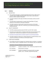
ACS800, multidrivesAir-cooledIGBT supply unitDrive unitsAuxiliary control unit (ACU)LCL fi lterIncoming unit (ICU)Liquid-cooled3-phaseHigh power brake unitDiode supply unitDrive units10 ABB industrial drives ACS800 multidrives | Catalog
Technical dataACS800 - X07(LC) - XXXX - X + XXXXMains connectionVoltage andpower rangeFrequencyPower factor DSUPower factor ISUTDHI (total harmonicdistortion of current) ISU < 5%Efficiency (at nominalpower)Motor connectionVoltagefor >500 V unitsFrequencyField weakening pointMotor control softwareTorque controlOpen loopClosed loopOpen loopClosed loopSpeed controlOpen loopClosed loopOpen loopClosed loopEnvironmental limitsAmbient temperatureTransportStorageOperationAir-cooledLiquid-cooledCooling methodAir-cooled3-phase, U 3IN= 380 to 415 V, ± 10%3-phase, U 5IN= 380 to 500 V, ± 10%3-phase, U 7IN= 525 to 690 V, ± 10%(600 V UL, CSA)48 to 63 Hzcosϕ 1= 0.98 (fundamental)cosϕ = 0.93 to 0.95 (total)cosϕ 1= 1 (fundamental)cosϕ 1= 0.99 (total)98%97% with ISU3-phase output voltage 0 to U 3IN /U 5IN /U 7INplease see “Filter selection table for ACS800”under the du/dt filters on page 290 to ± 300 Hz, also with built-in du/dt filters inR8i module0 to ± 120 Hz with external du/dt filters inR2i-R7i8 to 300 HzABB’s direct torque control (DTC)Torque step rise time:
Multidrive ratings, types and voltagesDrive unit, U N= 500 VACS800 - 107 - XXXX - 5 + XXXXNominal ratings No-overloaduseLight-overloaduseHeavy-duty use HeatdissipationType codeFramesizeI cont. max I max P cont. max I N P N I hd P hdA (AC) A kW A kW A kW kWU N = 500 V (Range 380 to 500 V)4.9 7 2.2 4.5 2.2 3.4 1.5 0.1 ACS800-107-0004-5 R2i6.2 8 3 5.6 3 4.2 2.2 0.1 ACS800-107-0005-5 R2i8.1 11 4 7.7 4 5.6 3 0.2 ACS800-107-0006-5 R2i11 14 5.5 10 5.5 7.5 4 0.2 ACS800-107-0009-5 R2i13 18 7.5 12 7.5 9.2 5.5 0.3 ACS800-107-0011-5 R2i19 24 11 18 11 13 7.5 0.3 ACS800-107-0016-5 R3i25 32 15 23 15 18 11 0.4 ACS800-107-0020-5 R3i34 46 18.5 31 18.5 23 15 0.5 ACS800-107-0025-5 R3i42 62 22 39 22 32 18.5 0.6 ACS800-107-0030-5 R4i48 72 30 44 30 36 22 0.8 ACS800-107-0040-5 R4i65 86 37 61 37 50 30 1 ACS800-107-0050-5 R5i79 112 45 75 45 60 37 1.2 ACS800-107-0060-5 R5i96 138 55 88 55 69 45 1.4 ACS800-107-0070-5 R5i115 172 75 110 55 86 55 1.1 ACS800-107-0105-5 R7i135 202 90 130 90 101 55 1.3 ACS800-107-0125-5 R7i166 248 110 159 110 124 75 1.7 ACS800-107-0145-5 R7i208 312 132 200 132 156 90 2 ACS800-107-0175-5 R7i250 374 160 240 160 187 110 2.2 ACS800-107-0215-5 R7i315 457 200 302 200 236 132 3.2 ACS800-107-0260-5 R8i365 530 250 350 250 273 160 4 ACS800-107-0320-5 R8i455 660 315 437 315 340 200 5.4 ACS800-107-0400-5 R8i525 762 355 504 355 393 250 5.9 ACS800-107-0460-5 R8i700 1016 500 672 500 524 355 7.8 ACS800-107-0610-5 R8i1050 1524 710 1008 710 785 560 12 ACS800-107-0910-5 2xR8i1372 1991 1000 1317 1000 1026 710 15 ACS800-107-1210-5 2xR8i2037 2956 1450 1956 1450 1524 1120 22 ACS800-107-1820-5 3xR8i2688 3901 2000 2580 1850 2011 1400 29 ACS800-107-2430-5 4xR8i3343 4850 2400 3209 2400 2500 1600 36 ACS800-107-3030-5 5xR8i3990 5790 2900 3830 2900 2985 2000 43 ACS800-107-3640-5 6xR8iStandard options:- Cable top exit- DC switch with capacitorcharging circuits- Ground fault protection withcurrent transformer(s)- Output du/dt fi lter, standardfor parallel connectedinverters- Common motor connectionterminals with parallelconnected invertersDimensionsFrame Height WidthsizeWidth Depth Weight Noise Noisewithtop exitlevel levelAirflowmm mm mm mm kg dB(A) dB(A) 5) m 3 /hR2i 2130 1) 400 2) - 644 180 62 - 35R3i 2130 1) 400 2) - 644 180 62 - 69R4i 2130 1) 400 2) - 644 180 62 - 103R5i 2130 1) 400 2) - 644 180 65 - 168R7i 2130 1) 400 600 4) 644 6) 200 72 - 800R8i 2130 1) 400 3) 700 3)4) 644 6) 320 72 60 12802xR8i 2130 1) 600 3) 900 3)4) 644 6) 510 74 62 25603xR8i 2130 1) 800 3) 1200 3)4) 644 6) 660 76 64 38404xR8i 2130 1) 1200 3) 1600 3)4) 644 6) 1020 76 64 51205xR8i 2130 1) 1400 3) 1800 3)4) 644 6) 1170 77 65 64006xR8i 2130 1) 1600 3) 2200 3)4) 644 6) 1320 78 66 76801)Cabinet height is 2315 mm for IP54 classifi cation and for IPXXR 2051 mm.An additional 10 mm is required for marine supports.2)1-3 x R2i, 1-3 x R3i, 1-2 x R4i, 1-2 x R5i.3)300 mm is required for Drive Control Unit (DCU). One DCU can be used for twodrive units.4)Delivered with additional cabinet(s), when top exit or common motor outputconnection is required.5)Average noise level with controlled cooling fan.6)Alternative for top exit with additional cabinet: Backpack, depth is an additional120 mm.Nominal ratings:I cont.max: rated current available continuously without overloadability at 40 °C.I max: maximum output current. Available for 10 s at start, otherwise as long as allowedby drive temperature.Typical ratings:No-overload useP cont.max: typical motor power in no-overload use.Light-overload useI N: continuous current allowing 110% I Nfor 1min / 5 min at 40 °C.P N: typical motor power in light-overload use.Heavy-duty useI hd: continuous current allowing 150% I hdfor 1min / 5 min at 40 °C.P hd: typical motor power in heavy-duty use.The current ratings are the same regardless of the supply voltage within one voltagerange.The ratings apply in 40 °C ambient temperature.In lower temperatures the ratings are higher (except I max).Dimensioning has to be checked with DriveSize.The rated current of the ACS800 must be higher than or equal to the rated motorcurrent to achieve the rated motor power given in the table.14 ABB industrial drives ACS800 multidrives | Catalog
Multidrive ratings, types and voltagesSupply unit, U N= 500 VACS800 - X07 - XXXX - 5 + XXXXNominal ratingsNo-overloaduseLight-overloaduseHeavy-dutyuseHeatdissipationType codeFramesizeI cont. max I cont. max I max S N P cont. max I N P N I hd P hdA (AC) A (DC) A (DC) kVA kW (DC) A (DC) kW (DC) A (DC) kW (DC) kWU N = 500 V (Range 380 to 500 V)IGBT supply unit (ISU)180 218 327 156 154 210 148 163 115 4 ACS800-207-0165-5 R7i220 267 394 191 189 256 181 200 141 4.4 ACS800-207-0195-5 R7i270 327 475 220 231 314 222 245 173 6.2 ACS800-207-0230-5 R8i360 436 633 312 309 419 296 327 231 8.4 ACS800-207-0310-5 R8i450 546 792 390 386 524 370 408 289 11 ACS800-207-0390-5 R8i600 727 1056 520 514 698 494 544 385 15 ACS800-207-0520-5 R8i900 1091 1584 779 772 1048 741 816 577 21 ACS800-207-0780-5 2xR8i1176 1426 2069 1018 1008 1369 968 1067 754 29 ACS800-207-1020-5 2xR8i1746 2117 3072 1512 1497 2032 1437 1584 1120 43 ACS800-207-1510-5 3xR8i2304 2794 4054 1995 1975 2682 1896 2090 1478 56 ACS800-207-2000-5 4xR8i3420 4147 6017 2962 2932 3981 2815 3102 2193 83 ACS800-207-2960-5 6xR8i6-pulse diode (DSU)286 350 462 247 229 335 219 280 183 1.5 ACS800-307-0250-5 D3408 500 700 353 327 480 314 400 262 2.4 ACS800-307-0350-5 D3571 700 924 495 458 670 439 560 367 3.8 ACS800-307-0490-5 D4816 1000 1400 707 655 960 629 800 524 5 ACS800-307-0710-5 D41143 1400 1848 990 917 1340 877 1120 733 7.6 ACS800-307-0990-5 2xD41518 1860 2604 1315 1218 1790 1172 1490 976 10 ACS800-307-1310-5 2xD42278 2790 3906 1972 1827 2685 1758 2230 1460 15 ACS800-307-1970-5 3xD43037 3720 5208 2630 2436 3580 2344 2980 1951 20 ACS800-307-2630-5 4xD43796 4650 6510 3287 3045 4475 2930 3720 2436 25 ACS800-307-3290-5 5xD46-pulse regenerative (TSU)981 1202 1947 850 792 1137 749 881 580 6.3 ACS800-407-0850-5 B41617 1980 3208 1400 1304 1872 1233 1450 955 10 ACS800-407-1400-5 B42449 3000 4860 2120 1976 2838 1869 2244 1478 17 ACS800-407-2120-5 B52858 3500 5670 2475 2305 3310 2180 2618 1724 21 ACS800-407-2600-5 B512-pulse diode (DSU)571 700 924 495 458 670 439 560 367 3.8 ACS800-507-0490-5 D4816 1000 1400 707 655 960 629 800 524 5 ACS800-507-0710-5 D41143 1400 1848 990 917 1340 877 1120 733 7.6 ACS800-507-0990-5 2xD41518 1860 2604 1315 1218 1790 1172 1490 976 10 ACS800-507-1310-5 2xD42278 2790 3906 1972 1827 2685 1758 2230 1460 15 ACS800-507-1970-5 3xD43037 3720 5208 2630 2436 3580 2344 2980 1951 20 ACS800-507-2630-5 4xD43796 4650 6510 3287 3045 4475 2930 3720 2436 25 ACS800-507-3290-5 5xD412-pulse regenerative (TSU)1864 2283 3700 1614 1504 2161 1423 1672 1101 13 ACS800-807-1615-5 B43072 3764 6094 2661 2479 3556 2342 2758 1816 20 ACS800-807-2660-5 B44653 5700 9234 4030 3754 5392 3551 4252 2800 33 ACS800-807-4030-5 B55430 6652 10773 4703 4381 6293 4144 4976 3277 42 ACS800-807-4700-5 B5Nominal ratings:I cont.max: rated currentavailable continuouslywithout overloadability at40 °C.I max: maximum outputcurrent.Typical ratings:No-overload useP cont.max: power in nooverloaduse.Light-overload useI N: continuous currentallowing 110% I Nfor1min / 5 min at 40 °C.P N: power in lightoverloaduse.Heavy-duty useI hd: continuous currentallowing 150% I hdfor1min / 5 min at 40 °C.P hd: power in heavy-dutyuse.The current ratings arethe same regardless ofthe supply voltage withinone voltage range.The ratings apply in 40 °Cambient temperature. Inlower temperatures theratings are higher (exceptI max).Dimensions (for ACU, ICU and ISU/DSU/TSU)Frame size Height Width Depth Weight Noise level Air flowmm mm mm kg dB(A) dB(A) 4) m 3 /hIGBT supply unit (ISU)R7i 2130 1) 1000 644 350 72 - 1300R8i 2130 1) 1400 2) 644 950 74 62 18802xR8i 2130 1) 2000 3) 644 1750 76 64 38403xR8i 2130 1) 2600 3) 644 2400 78 66 64004xR8i 2130 1) 2800 3) 644 2580 78 66 76806xR8i 2130 1) 3600 3) 644 3600 80 68 115206-pulse diode (DSU)D3 2130 1) 1200 644 840 65 55 720D4 2130 1) 1200 644 840 65 55 7202xD4 2130 1) 1800 644 1060 67 57 14403xD4 2130 1) 2000 3) 644 1330 68 58 21604xD4 2130 1) 2400 3) 644 1900 69 59 28805xD4 2130 1) 3000 3) 644 2170 70 60 3600Frame size Height Width Depth Weight Noise level Air flowmm mm mm kg dB(A) dB(A) 4) m 3 /h6-pulse regenerative (TSU)B4 2130 1) 2800 644 1690 72 - 2500B5 2130 1) 2800 644 2090 75 - 450012-pulse diode (DSU)D4 2130 1) 1300 644 840 65 55 7202xD4 2130 1) 1700 644 1060 67 57 14403xD4 2130 1) 2600 3) 644 1330 68 58 21604xD4 2130 1) 3000 3) 644 1900 69 59 28805xD4 2130 1) 3200 3) 644 2170 70 60 360012-pulse regenerative (TSU)B4 2130 5200 644 3290 74 - 5000B5 2130 5200 644 3290 77 - 90001)Cabinet height is 2315 mm for IP54 classifi cation and for IPXXR 2051 mm.An additional 10 mm is required for marine supports.2)Width 1600 mm if UL or CSA approved3)An additional 300 mm cabinet is required when top connection of supplycables is needed.4)Average noise level with controlled cooling fan.Catalog | ABB industrial drives ACS800 multidrives 15
Multidrive ratings, types and voltagesDrive unit, U N= 690 VACS800 - 107 - XXXX - 7 + XXXXNominal ratings No-overloaduseLight-overloaduseHeavy-duty use HeatdissipationType codeFramesizeI cont. max I max P cont. max I N P N I hd P hdA (AC) A kW A kW A kW kWU N = 690 V (Range 525 to 690 V)13 14 11 12 7.5 8.5 5.5 0.3 ACS800-107-0011-7 R4i17 19 15 16 11 11 7.5 0.3 ACS800-107-0016-7 R4i22 28 18.5 21 15 15 11 0.4 ACS800-107-0020-7 R4i25 38 22 24 18.5 19 15 0.5 ACS800-107-0025-7 R4i33 44 30 32 22 22 18.5 0.6 ACS800-107-0030-7 R4i36 54 30 35 30 27 22 0.7 ACS800-107-0040-7 R4i51 68 45 49 37 34 30 0.8 ACS800-107-0050-7 R5i57 84 55 55 45 42 37 1 ACS800-107-0060-7 R5i69 104 55 66 55 52 45 1.1 ACS800-107-0075-7 R7i88 132 75 84 75 66 55 1.3 ACS800-107-0105-7 R7i105 158 90 101 90 79 75 1.6 ACS800-107-0125-7 R7i132 198 110 127 110 99 90 2 ACS800-107-0145-7 R7i150 224 132 144 132 112 90 2.3 ACS800-107-0175-7 R7i170 254 160 163 160 127 110 2.6 A CS800-107-0215-7 R7i215 322 200 206 200 161 160 3.6 ACS800-107-0260-7 R8i289 432 250 277 250 216 200 4.8 ACS800-107-0320-7 R8i336 503 315 323 315 251 240 6.1 ACS800-107-0400-7 R8i382 571 355 367 355 286 270 7 ACS800-107-0440-7 R8i486 727 450 467 450 364 355 7.5 ACS800-107-0580-7 R8i729 1091 710 700 710 545 500 13 ACS800-107-0870-7 2xR8i953 1425 900 914 900 713 710 15 ACS800-107-1160-7 2xR8i1414 2116 1400 1358 1400 1058 1000 22 ACS800-107-1740-7 3xR8i1866 2792 1900 1792 1800 1396 1400 29 ACS800-107-2320-7 4xR8i2321 3472 2300 2228 2200 1736 1600 35 ACS800-107-2900-7 5xR8i2770 4144 2800 2659 2700 2072 2000 42 ACS800-107-3490-7 6xR8i3232 4835 3200 3103 3100 2417 2400 49 ACS800-107-4070-7 7xR8i3694 5526 3700 3546 3600 2763 2800 56 ACS800-107-4650-7 8xR8i4155 6216 4200 3989 4000 3108 3100 63 ACS800-107-5230-7 9xR8i4617 6907 4600 4432 4500 3454 3500 70 ACS800-107-5810-7 10xR8i5079 7598 5100 4876 4900 3799 3800 77 ACS800-107-6390-7 11xR8i5540 8288 5600 5319 5400 4144 4200 84 ACS800-107-6970-7 12xR8iStandard options:- Cable top exit- DC switch with capacitorcharging circuits- Ground fault protection withcurrent transformer(s)- Output du/dt fi lter, standardfor parallel connectedinverters- Common motor connectionterminals with parallelconnected invertersDimensionsFrame Height WidthsizeWidth Depth Weight Noise Noisewithtop exitlevel levelAirflowmm mm mm mm kg dB(A) dB(A) 5) m 3 /hR4i 2130 1) 400 2) - 644 180 62 - 103R5i 2130 1) 400 2) - 644 180 65 - 168R7i 2130 1) 400 600 4) 644 6) 200 72 - 800R8i 2130 1) 400 3) 700 3)4) 644 6) 320 72 60 12802xR8i 2130 1) 600 3) 900 3)4) 644 6) 510 74 62 25603xR8i 2130 1) 800 3) 1200 3)4) 644 6) 660 76 64 38404xR8i 2130 1) 1200 3) 1600 3)4) 644 6) 1020 76 64 51205xR8i 2130 1) 1400 3) 1800 3)4) 644 6) 1170 77 65 64006xR8i 2130 1) 1600 3) 2200 4) 644 6) 1320 78 66 76807xR8i 2130 1) 2000 3) 2600 4) 644 6) 1680 78 66 89608xR8i 2130 1) 2200 3)) 3000 4) 644 6) 1830 79 67 102409x8Ri 2130 1) 2400 3) 3200 4) 644 6) 1980 79 67 1152010xR8i 2130 1) 2800 3) 3800 4) 644 6) 2340 79 67 1280011xR8i 2130 1) 3000 3) 4200 4) 644 6) 2490 79 67 1408012xR8i 2130 1) 3200 3) 4400 4) 644 6) 2640 79 67 153601)Cabinet height is 2315 mm for IP54 classifi cation and for IPXXR 2051 mm.An additional 10 mm is required for marine supports.2)1-3 x R2i, 1-3 x R3i, 1-2 x R4i, 1-2 x R5i.3)300 mm is required for Drive Control Unit (DCU). One DCU can be used for twodrive units.4)Delivered with additional cabinet(s), when top exit or common motor outputconnection is required.5)Average noise level with controlled cooling fan.6)Alternative for top exit with additional cabinet: Backpack, depth is an additional120 mm.Nominal ratings:I cont.max: rated current available continuously without overloadability at 40 °C.I max: maximum output current. Available for 10 s at start, otherwise as long as allowedby drive temperature.Typical ratings:No-overload useP cont.max: typical motor power in no-overload use.Light-overload useI N: continuous current allowing 110% I Nfor 1min / 5 min at 40 °C.P N: typical motor power in light-overload use.Heavy-duty useI hd: continuous current allowing 150% I hdfor 1min / 5 min at 40 °C.P hd: typical motor power in heavy-duty use.The current ratings are the same regardless of the supply voltage within one voltagerange.The ratings apply in 40 °C ambient temperature.In lower temperatures the ratings are higher (except I max).Dimensioning has to be checked with DriveSize.The rated current of the ACS800 must be higher than or equal to the rated motorcurrent to achieve the rated motor power given in the table.16 ABB industrial drives ACS800 multidrives | Catalog
Multidrive ratings, types and voltagesSupply unit, U N= 690 VACS800 - X07 - XXXX - 7 + XXXXNominal ratingsNo-overloaduseLight-overloaduseHeavy-dutyuseHeatdissipationType codeFramesizeI cont. max I cont. max I max S N P cont. max I N P N I hd P hdA (AC) A (DC) A (DC) kVA kW (DC) A (DC) kW (DC) A (DC) kW (DC) kWU N = 690 V (Range 525 to 690 V)IGBT supply unit (ISU)119 144 216 142 141 139 135 108 105 4.6 ACS800-207-0155-7 R7i135 164 245 161 160 157 153 122 119 5.2 ACS800-207-0175-7 R7i180 218 327 215 213 210 204 163 159 8.3 ACS800-207-0220-7 R8i250 303 453 299 296 291 284 227 221 9.4 ACS800-207-0300-7 R8i300 364 544 359 355 349 341 272 266 13 ACS800-207-0360-7 R8i400 485 726 478 473 466 454 363 354 15 ACS800-207-0480-7 R8i600 727 1088 717 710 698 682 544 531 27 ACS800-207-0720-7 2xR8i784 951 1422 937 928 913 890 711 694 29 ACS800-207-0940-7 2xR8i1164 1411 2111 1391 1377 1355 1322 1056 1030 42 ACS800-207-1390-7 3xR8i1536 1862 2786 1836 1817 1788 1745 1393 1359 56 ACS800-207-1840-7 4xR8i2280 2764 4136 2725 2698 2654 2590 2068 2018 83 ACS800-207-2730-7 6xR8i3040 3686 5514 3633 3597 3539 3453 2757 2690 110 ACS800-207-3630-7 8xR8i3800 4607 6893 4541 4496 4423 4316 3446 3363 138 ACS800-207-4550-7 10xR8i4560 5529 8271 5450 5395 5308 5179 4136 4036 165 ACS800-207-5450-7 12xR8i6-pulse diode (DSU)286 350 462 341 316 335 303 280 253 1.5 ACS800-307-0340-7 D3408 500 700 488 452 480 434 400 361 2.4 ACS800-307-0490-7 D3571 700 924 683 632 670 605 560 506 3.8 ACS800-307-0680-7 D4816 1000 1400 976 904 960 867 800 723 5 ACS800-307-0980-7 D41143 1400 1848 1366 1265 1340 1211 1120 1012 7.6 ACS800-307-1370-7 2xD41518 1860 2604 1815 1681 1790 1617 1490 1346 10 ACS800-307-1810-7 2xD42278 2790 3906 2722 2521 2685 2426 2230 2015 15 ACS800-307-2720-7 3xD43037 3720 5208 3629 3361 3580 3235 2980 2693 20 ACS800-307-3630-7 4xD43796 4650 6510 4537 4202 4475 4043 3720 3361 25 ACS800-307-4540-7 5xD46-pulse regenerative (TSU)711 871 1411 850 784 824 742 637 574 6.3 ACS800-407-0850-7 B41171 1435 2325 1400 1292 1353 1219 1050 946 10 ACS800-407-1400-7 B42176 2664 4316 2600 2399 2519 2269 1993 1795 17 ACS800-407-2600-7 B52858 3500 5670 3415 3152 3311 2982 2618 2358 21 ACS800-407-3600-7 B512-pulse diode (DSU)571 700 924 683 632 670 605 560 506 3.8 ACS800-507-0680-7 D4816 1000 1400 976 904 960 867 800 723 5 ACS800-507-0980-7 D41143 1400 1848 1366 1265 1340 1211 1120 1012 7.6 ACS800-507-1370-7 2xD41518 1860 2604 1815 1681 1790 1617 1490 1346 10 ACS800-507-1810-7 2xD42278 2790 3906 2722 2521 2685 2426 2230 2015 15 ACS800-507-2720-7 3xD43037 3720 5208 3629 3361 3580 3235 2980 2693 20 ACS800-507-3630-7 4xD43796 4650 6510 4537 4202 4475 4043 3720 3361 25 ACS800-507-4540-7 5xD412-pulse regenerative (TSU)1351 1655 2681 1614 1490 1564 1409 1211 1091 13 ACS800-807-1615-7 B42225 2726 4417 2659 2455 2576 2320 1996 1798 20 ACS800-807-2660-7 B44134 5065 8200 4941 4561 4790 4314 3788 3412 33 ACS800-807-4950-7 B55430 6652 10773 6490 5991 6292 5667 4975 4481 42 ACS800-807-6500-7 B5Nominal ratings:I cont.max: rated currentavailable continuouslywithout overloadability at40 °C.I max: maximum outputcurrent.Typical ratings:No-overload useP cont.max: power in nooverloaduse.Light-overload useI N: continuous currentallowing 110% I Nfor1min / 5 min at 40 °C.P N: power in lightoverloaduse.Heavy-duty useI hd: continuous currentallowing 150% I hdfor1min / 5 min at 40 °C.P hd: power in heavy-dutyuse.The current ratings arethe same regardless ofthe supply voltage withinone voltage range.The ratings apply in 40 °Cambient temperature. Inlower temperatures theratings are higher (exceptI max).Dimensions (for ACU, ICU and ISU/DSU/TSU)Frame size Height Width Depth Weight Noise level Air flowmm mm mm kg dB(A) dB(A) 4) m 3 /hIGBT supply unit (ISU)R7i 2130 1) 1000 644 350 72 - 1300R8i 2130 1) 1400 2) 644 950 74 62 18802xR8i 2130 1) 2000 3) 644 1750 76 64 38403xR8i 2130 1) 2600 3) 644 2400 78 66 64004xR8i 2130 1) 2800 3) 644 2580 78 66 76806xR8i 2130 1) 3600 3) 644 3400 80 68 115208xR8i 2130 1) 4400 3) 644 4250 81 69 1536010xR8i 2130 1) 5600 3) 644 5280 81 69 1920012xR8i 2130 1) 6400 3) 644 6100 81 69 230406-pulse diode (DSU)D3 2130 1) 1200 644 840 65 55 720D4 2130 1) 1200 644 840 65 55 7202xD4 2130 1) 1800 644 1060 67 57 14403xD4 2130 1) 2000 3) 644 1330 68 58 21604xD4 2130 1) 2400 3) 644 1900 69 59 28805xD4 2130 1) 3000 3) 644 2170 70 60 3600Frame size Height Width Depth Weight Noise level Air flowmm mm mm kg dB(A) dB(A) 4) m 3 /h6-pulse regenerative (TSU)B4 2130 1) 2800 644 1690 72 - 2500B5 2130 1) 2800 644 2090 75 - 450012-pulse diode (DSU)D4 2130 1) 1300 644 840 65 55 7202xD4 2130 1) 1700 644 1060 67 57 14403xD4 2130 1) 2600 3) 644 1330 68 58 21604xD4 2130 1) 3000 3) 644 1900 69 59 28805xD4 2130 1) 3200 3) 644 2170 70 60 360012-pulse regenerative (TSU)B4 2130 5200 644 3290 74 - 5000B5 2130 5200 644 3290 77 - 90001)Cabinet height is 2315 mm for IP54 classifi cation and for IPXXR 2051 mm.An additional 10 mm is required for marine supports.2)Width 1600 mm if UL or CSA approved3)An additional 300 mm cabinet is required when top connection of supplycables is needed.4)Average noise level with controlled cooling fan.Catalog | ABB industrial drives ACS800 multidrives 17
ACS800 liquid-cooled multidrivesACS800-X07LC, 1.1 to 5600 kWACS800 - X07LC - XXXX - X + XXXXAdvanced liquid coolingThe ACS800 liquid-cooled multidrive with direct liquidcooling and robust design is an ultimate solution for variousapplications where space savings and silent operation is amust.Since the coolant takes care of 98% of the heat losses, noadditional filtered air-cooling is needed. This decreases thenoise level and increases the total efficiency of the converterinstallation. The high-efficiency liquid cooling removes theneed for air-conditioning in the installation rooms, bringing theinstallation and operation costs down. The totally enclosedcabinet structure makes the ACS800 liquid-cooled multidrivesperfect for harsh environmental conditions.The ACS800 liquid-cooled multidrives are available from 1.1 kWup to 5600 kW at 380 to 690V supply voltage.Customer specific designThe modular hardware design and advanced softwarefeatures of the liquid-cooled multidrive enable the mostsophisticated drive solutions for both induction andpermanent magnet motors. Our customized solutions providethe optimum customer benefits.Intelligence and high availabilityThe ABB ACS800 liquid-cooled series has a number of uniquefeatures as standard, and which are not available in previousgenerations of ABB drives, nor in existing competitors’ drives.These include:− Built-in redundancy through parallel connected modules -each module is a complete three-phase inverter.− Ability to run with partial load even when one of themodules is not operating- enabling higher drive availabilityand greater process uptime.With ABB drives, you get more than the most reliableequipment and systems. ABB drives are backed by our fullservice and support network, which covers field service andtraining as well as spare parts. This ensures reliable andeconomic operation under all conditions.“Compact and easy” – are the watchwords to describe theentire ACS800 liquid-cooled drive range. They demonstratehow technology enables ABB to add more and more featuresinto a shrinking space – and still give the benefits of easyinstallation, access and use.The design meets the international standards and marineclassification requirements. ABB’s extensive application andproduct know-how is at your service.18 ABB industrial drives ACS800 multidrives | Catalog
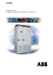
ACS800 liquid-cooled multidrivesRatings, types and voltagesDrive unit, U N= 400 VACS800 - X07LC - XXXX - X + XXXXNominal ratings No-overloaduseLight-overloaduseHeavy-dutyuseNoiselevelDissipationto liquidMassflow LiquidQtyType codeFramesizeI cont.max I max P cont.max I N P N I hd P hdA (AC) A (AC) kW A kW A kW dB(A) kW l/min lU N = 400 V (Range 380 to 415 V)5.1 6.5 1.5 4.7 1.5 3.4 1.1 60 0.1 6 1) 2.3 1) ACS800-107LC-0003-3 R2i6.5 8.2 2.2 5.9 2.2 4.3 1.5 60 0.1 6 1) 2.3 1) ACS800-107LC-0004-3 R2i8.5 10.8 3 7.7 3 5.7 2.2 60 0.1 6 1) 2.3 1) ACS800-107LC-0005-3 R2i11 13.8 4 10 4 7.5 3 60 0.1 6 1) 2.3 1) ACS800-107LC-0006-3 R2i14 17.6 5.5 13 5.5 9.3 4 60 0.2 6 1) 2.3 1) ACS800-107LC-0009-3 R2i19 24 7.5 18 7.5 14 5.5 60 0.3 6 1) 2.3 1) ACS800-107LC-0011-3 R3i25 32 11 24 11 19 7.5 60 0.3 6 1) 2.3 1) ACS800-107LC-0016-3 R3i34 46 15 31 15 23 11 60 0.4 6 1) 2.3 1) ACS800-107LC-0020-3 R3i44 62 22 41 18.5 32 15 60 0.5 6 1) 2.3 1) ACS800-107LC-0025-3 R4i55 72 30 50 22 37 18.5 60 0.6 6 1) 2.3 1) ACS800-107LC-0030-3 R4i72 86 37 69 30 49 22 63 0.8 6 1) 2.3 1) ACS800-107LC-0040-3 R5i86 112 45 80 37 60 30 63 1 6 1) 2.3 1) ACS800-107LC-0050-3 R5i103 138 55 94 45 69 37 63 1.2 6 1) 2.3 1) ACS800-107LC-0060-3 R5i176 251 90 169 90 132 55 53 1.6 13 2.3 ACS800-107LC-0120-3 R7i214 251 110 205 110 160 75 53 2 13 2.3 ACS800-107LC-0150-3 R7i250 335 132 240 132 187 90 53 2.3 13 2.3 ACS800-107LC-0170-3 R7i300 448 160 288 160 224 110 53 2.5 13 2.3 ACS800-107LC-0210-3 R7i350 524 200 336 200 262 132 53 3.7 13 2.5 ACS800-107LC-0240-3 R8i444 558 250 426 250 332 160 53 4.9 13 2.5 ACS800-107LC-0310-3 R8i563 674 315 540 315 421 200 53 5.8 13 2.5 ACS800-107LC-0390-3 R8i678 837 355 651 355 507 250 53 7.1 13 2.5 ACS800-107LC-0470-3 R8i889 1037 500 853 400 665 355 53 9 13 2.5 ACS800-107LC-0620-3 R8i1103 1279 630 1059 560 825 450 55 11.2 26 5 ACS800-107LC-0760-3 2xR8i1329 1590 710 1276 710 994 500 55 13.9 26 5 ACS800-107LC-0920-3 2xR8i1742 1994 900 1673 900 1303 710 55 17.5 26 5 ACS800-107LC-1210-3 2xR8i1973 2347 1120 1894 1120 1476 900 57 20.5 39 7.5 ACS800-107LC-1370-3 3xR8i2587 2941 1400 2484 1400 1935 1120 57 26 39 7.5 ACS800-107LC-1790-3 3xR8i3414 3906 2000 3277 2000 2553 1400 58 34.1 52 10 ACS800-107LC-2370-3 4xR8i4245 4858 2500 4075 2240 3175 1800 59 42.4 65 12.5 ACS800-107LC-2940-3 5xR8i5067 5799 2800 4865 2800 3790 2000 59 50.4 78 15 ACS800-107LC-3510-3 6xR8i1)Massfl ow and liquid quantity per 400 mm cabinet (see also 4) below)DimensionsInverter unitsFramesize2) 3)HeightmmWidthmmDepth 1)mmWeightkgR2i 2003 400 4) 644 180R3i 2003 400 4) 644 180R4i 2003 400 4) 644 180R5i 2003 400 4) 644 180R7i 2003 300 5) 644 220R8i 2003 300 5) 644 3002xR8i 2003 500 644 4503xR8i 2003 700 644 6004xR8i 2003 1000 644 9005xR8i 2003 1200 644 11006xR8i 2003 1400 644 13002)Total height with marine supports is 2088 mm and depth with marine handles718 mm.3)Pressure release lids require an additional 400 mm.4)R2i+R2i to R3i+R5i fi t in one 400 mm cabinet, R4i+R4i to R5i+R5i need two400 mm cabinets.5)Width with DC-switch is 400 mm.2xR8i inverter unitCatalog | ABB industrial drives ACS800 multidrives 19
ACS800 liquid-cooled multidrivesRatings, types and voltagesSupply unit, U N= 400 VACS800 - X07LC - XXXX - X + XXXXNominal ratingsNo overloadLight overload Heavy-duty Noise Dissipation Massflow Liquid Type codeFrameuse useuselevel to liquidQtysizeI contmax I contmax I max S N P contmax I n P N I hd P hdA (AC) A (DC) A (DC) kVA kW (DC) A (DC) kW A (DC) kW dB(A) kW l/min lU N = 400 V (Range 380 to 415 V)IGBT supply unit341 413 471 245 243 397 233 309 181 57 7.2 32 7.8 ACS800-207LC-0240-3 R8i454 550 627 326 323 528 310 411 241 57 8.5 32 7.8 ACS800-207LC-0330-3 R8i567 687 784 408 403 660 387 514 302 57 9.9 32 7.8 ACS800-207LC-0410-3 R8i756 917 1046 543 538 880 516 686 402 57 12.6 32 7.8 ACS800-207LC-0540-3 R8i1134 1375 1568 815 807 1320 775 1028 604 59 18.7 53 11.1 ACS800-207LC-0820-3 2xR8i1482 1797 2049 1065 1054 1725 1012 1344 789 59 24.8 53 11.1 ACS800-207LC-1070-3 2xR8i2200 2667 3042 1581 1565 2560 1503 1995 1171 61 37 77 14.6 ACS800-207LC-1580-3 3xR8i2903 3520 4015 2087 2066 3379 1983 2633 1545 62 48.7 100 18.9 ACS800-207LC-2090-3 4xR8i4309 5225 5960 3097 3066 5016 2944 3908 2294 64 72.4 148 25.9 ACS800-207LC-3100-3 6xR8iDiode supply unit6-pulse diode (DSU)572 700 980 396 378 672 363 560 303 56 2.2 19 2.2 ACS800-307LC-0400-3 D3898 1100 1540 622 594 1056 570 880 475 56 3.5 19 2.2 ACS800-307LC-0620-3 D31143 1400 1960 792 756 1344 726 1120 605 56 4.4 19 2.3 ACS800-307LC-0790-3 D41796 2200 3080 1245 1188 2112 1141 1760 951 56 7 19 2.3 ACS800-307LC-1240-3 D42126 2604 3646 1473 1407 2500 1350 2083 1125 58 8.3 38 4.6 ACS800-307LC-1470-3 2xD43200 3919 5487 2217 2117 3762 2032 3135 1694 58 12.4 38 4.6 ACS800-307LC-2220-3 2xD45000 6124 8574 3464 3308 5879 3176 4899 2646 60 19.5 57 6.9 ACS800-307LC-3460-3 3xD412-pulse diode (DSU)1143 1400 1960 792 756 1344 726 1120 605 56 4.4 19 2.3 ACS800-507LC-0790-3 D41796 2200 3080 1245 1188 2112 1141 1760 951 56 7 19 2.3 ACS800-507LC-1240-3 D42126 2604 3646 1473 1407 2500 1350 2083 1125 58 8.3 38 4.6 ACS800-507LC-1470-3 2xD43200 3919 5487 2217 2117 3762 2032 3135 1694 58 12.4 38 4.6 ACS800-507LC-2220-3 2xD45000 6124 8574 3464 3308 5879 3176 4899 2646 60 19.5 57 6.9 ACS800-507LC-3460-3 3xD418-pulse diode (DSU)1595 1953 2734 1105 1055 1875 1013 1562 844 58 6.2 38 4.5 ACS800-1107LC-1100-3 D3+D42506 3069 4297 1736 1658 2946 1592 2455 1326 58 9.7 38 4.5 ACS800-1107LC-1740-3 D3+D43189 3906 5468 2210 2110 3750 2026 3125 1688 60 12.4 57 6.9 ACS800-1107LC-2210-3 3xD45000 6124 8574 3464 3308 5879 3176 4899 2646 60 19.5 57 6.9 ACS800-1107LC-3460-3 3xD424-pulse diode (DSU)2126 2604 3646 1473 1407 2500 1350 2083 1125 58 8.3 38 4.6 ACS800-1207LC-1470-3 2xD43200 3919 5487 2217 2117 3762 2032 3135 1694 58 12.4 38 4.6 ACS800-1207LC-2220-3 2xD4Supply unitsFrame Height 1)2) WidthsizeWidth withmain breakerDepth 1)Weightmm mm mmmm kgIGBT supply unitR8i 2003 - 1000/1200 3) 644 850/1150 3)2xR8i 2003 - 1400 644 15003xR8i 2003 - 2400 644 23504xR8i 2003 - 2200 644 24506xR8i 2003 - 3400 644 36506-pulse diode (DSU)D3 2003 400 800/1000 4) 644 920/1120 4)D4 2003 400 1000 644 11202xD4 2003 800 1400 644 15403xD4 2003 1200 2200 644 216012-pulse diode (DSU)D4 2003 400 1200 644 1420D4 2003 400 1600 644 18202xD4 2003 800 2000 644 22403xD4 2003 1200 2400 644 266018-pulse diode (DSU)D3+D4 2003 800 2000 644 2340D3+D4 2003 800 2600 644 29403xD4 2003 1200 3000 644 336024-pulse diode (DSU)2xD4 2003 800 2400 644 28402xD4 2003 800 3200 644 36401)Total height with marine supports is 2088 mm and depth with marine handles718 mm.2)Pressure release lids require an additional 400 mm.3)The latter values only for type 0540-3.4)The latter values only for type 0620-3.20 ABB industrial drives ACS800 multidrives | Catalog
ACS800 liquid-cooled multidrivesRatings, types and voltagesDrive unit, U N= 500 VACS800 - X07LC - XXXX - X + XXXXNominal ratings No-overloaduseLight-overloaduseHeavy-dutyuseNoiselevelDissipationto liquidMassflow LiquidQtyType codeFramesizeI cont.max I max P cont.max I N P N I hd P hdA (AC) A (AC) kW A kW A kW dB(A) kW l/min lU N = 500 V (Range 380 to 500 V)4.9 6.5 2.2 4.5 2.2 3.4 1.5 60 0.1 6 1) 2.3 1) ACS800-107LC-0004-5 R2i6.2 8.2 3 5.6 3 4.2 2.2 60 0.1 6 1) 2.3 1) ACS800-107LC-0005-5 R2i8.1 10.8 4 7.7 4 5.6 3 60 0.2 6 1) 2.3 1) ACS800-107LC-0006-5 R2i11 14 5.5 10 5.5 7.5 4 60 0.2 6 1) 2.3 1) ACS800-107LC-0009-5 R2i13 18 7.5 12 7.5 9.2 5.5 60 0.3 6 1) 2.3 1) ACS800-107LC-0011-5 R2i19 24 11 18 11 13 7.5 60 0.3 6 1) 2.3 1) ACS800-107LC-0016-5 R3i25 32 15 23 15 18 11 60 0.4 6 1) 2.3 1) ACS800-107LC-0020-5 R3i34 46 18.5 31 18.5 23 15 60 0.5 6 1) 2.3 1) ACS800-107LC-0025-5 R3i42 62 22 39 22 32 18.5 60 0.6 6 1) 2.3 1) ACS800-107LC-0030-5 R4i48 72 30 44 30 36 22 60 0.8 6 1) 2.3 1) ACS800-107LC-0040-5 R4i65 86 37 61 37 50 30 63 1 6 1) 2.3 1) ACS800-107LC-0050-5 R5i79 112 45 75 45 60 37 63 1.2 6 1) 2.3 1) ACS800-107LC-0060-5 R5i96 138 55 88 55 69 45 63 1.4 6 1) 2.3 1) ACS800-107LC-0070-5 R5i138 206 90 132 90 103 55 53 1.3 13 2.3 ACS800-107LC-0120-5 R7i162 242 110 156 110 121 75 53 1.5 13 2.3 ACS800-107LC-0140-5 R7i199 252 132 191 132 149 90 53 2 13 2.3 ACS800-107LC-0170-5 R7i250 335 160 240 160 187 110 53 2.4 13 2.3 ACS800-107LC-0220-5 R7i300 448 200 288 200 224 160 53 2.6 13 2.3 ACS800-107LC-0260-5 R7i378 558 250 363 250 283 200 53 4.3 13 2.5 ACS800-107LC-0330-5 R8i438 558 315 420 315 328 250 53 5.1 13 2.5 ACS800-107LC-0380-5 R8i546 673 355 524 355 408 315 53 5.9 13 2.5 ACS800-107LC-0470-5 R8i630 838 400 605 400 471 355 53 6.9 13 2.5 ACS800-107LC-0550-5 R8i840 1042 560 806 560 628 400 53 8.8 13 2.5 ACS800-107LC-0730-5 R8i1070 1280 710 1027 710 800 560 55 11.3 26 5 ACS800-107LC-0930-5 2xR8i1235 1589 900 1185 900 924 630 55 13.3 26 5 ACS800-107LC-1070-5 2xR8i1646 1996 1120 1581 1120 1232 710 55 17 26 5 ACS800-107LC-1430-5 2xR8i1833 2344 1250 1760 1250 1371 900 57 19.7 39 7.5 ACS800-107LC-1590-5 3xR8i2444 2943 1600 2347 1600 1828 1250 57 25.4 39 7.5 ACS800-107LC-2120-5 3xR8i3226 3885 2240 3097 2240 2413 1600 58 33.2 52 10 ACS800-107LC-2790-5 4xR8i4011 4830 2800 3851 2800 3000 2000 59 41.3 65 12.5 ACS800-107LC-3470-5 5xR8i4788 5801 3360 4596 3200 3581 2500 59 49 78 15 ACS800-107LC-4150-5 6xR8i1)Massfl ow and liquid quantity per 400 mm cabinet (see also 4) below)DimensionsInverter unitsFramesize2) 3)HeightmmWidthmmDepth 1)mmWeightkgR2i 2003 400 4) 644 180R3i 2003 400 4) 644 180R4i 2003 400 4) 644 180R5i 2003 400 4) 644 180R7i 2003 300 5) 644 220R8i 2003 300 5) 644 3002xR8i 2003 500 644 4503xR8i 2003 700 644 6004xR8i 2003 1000 644 9005xR8i 2003 1200 644 11006xR8i 2003 1400 644 13002)Total height with marine supports is 2088 mm and depth with marine handles718 mm.3)Pressure release lids require an additional 400 mm.4)R2i+R2i to R3i+R5i fi t in one 400 mm cabinet, R4i+R4i to R5i+R5i need two400 mm cabinets.5)Width with DC-switch is 400 mm.Nominal ratings:I cont.max: rated current available continuously without overloadability at 40 °C.I max: maximum output current. Available for 10 s at start, otherwise as long asallowed by drive temperature.Typical ratings:No-overload useP cont.max: typical motor power in no-overload use.Light-overload useI N: continuous current allowing 110% I Nfor 1min / 5 min at 40 °C.P N: typical motor power in light-overload use.Heavy-duty useI hd: continuous current allowing 150% I hdfor 1min / 5 min at 40 °C.P hd: typical motor power in heavy-duty use.The current ratings are the same regardless of the supply voltage within one voltagerange.The ratings apply in 40 °C ambient temperature.In lower temperatures the ratings are higher (except I max).The rated current of the ACS800 must be higher than or equal to the rated motorcurrent to achieve the rated motor power given in the table.Catalog | ABB industrial drives ACS800 multidrives 21
ACS800 liquid-cooled multidrivesRatings, types and voltagesSupply unit, U N= 500 VACS800 - X07LC - XXXX - X + XXXXNominal ratingsNo overloadLight overload Heavy-duty Noise Dissipation Massflow Liquid Type codeFrameuse useuselevel to liquidQtysizeI contmax I contmax I max S N P contmax I n P N I hd P hdA (AC) A (DC) A (DC) kVA kW (DC) A (DC) kW A (DC) kW dB(A) kW l/min lU N = 500 V (Range 380 to 500 V)IGBT supply unit324 393 475 281 278 377 267 294 208 57 7.3 32 7.8 ACS800-207LC-0280-5 R8i432 524 633 374 370 503 356 392 277 57 8.6 32 7.8 ACS800-207LC-0370-5 R8i540 655 792 468 463 629 444 490 346 57 10 32 7.8 ACS800-207LC-0470-5 R8i720 873 1056 624 617 838 593 653 462 57 12.8 32 7.8 ACS800-207LC-0620-5 R8i1080 1309 1584 935 926 1257 889 980 693 59 18.9 53 11.1 ACS800-207LC-0940-5 2xR8i1411 1711 2069 1222 1210 1643 1162 1280 905 59 25 53 11.1 ACS800-207LC-1220-5 2xR8i2095 2540 3072 1814 1796 2439 1724 1900 1344 61 37.4 77 14.6 ACS800-207LC-1810-5 3xR8i2765 3352 4054 2394 2370 3218 2276 2508 1773 62 49.2 100 18.9 ACS800-207LC-2390-5 4xR8i4104 4976 6017 3554 3519 4777 3378 3722 2632 64 73.1 148 25.9 ACS800-207LC-3550-5 6xR8iDiode supply unit6-pulse diode (DSU)572 700 980 495 473 672 454 560 378 56 2.8 19 2.2 ACS800-307LC-0490-5 D3898 1100 1540 778 743 1056 713 880 594 56 4.4 19 2.2 ACS800-307LC-0780-5 D31143 1400 1960 990 945 1344 908 1120 756 56 5.6 19 2.3 ACS800-307LC-0990-5 D41796 2200 3080 1556 1486 2112 1426 1760 1188 56 8.7 19 2.3 ACS800-307LC-1560-5 D42126 2604 3646 1841 1758 2500 1688 2083 1407 58 10.3 38 4.6 ACS800-307LC-1840-5 2xD43200 3919 5487 2771 2646 3762 2540 3135 2117 58 15.6 38 4.6 ACS800-307LC-2770-5 2xD45000 6124 8574 4330 4135 5879 3970 4899 3308 60 24.3 57 6.9 ACS800-307LC-4330-5 3xD412-pulse diode (DSU)1143 1400 1960 990 945 1344 908 1120 756 56 5.6 19 2.3 ACS800-507LC-0990-5 D41796 2200 3080 1556 1486 2112 1426 1760 1188 56 8.7 19 2.3 ACS800-507LC-1560-5 D42126 2604 3646 1841 1758 2500 1688 2083 1407 58 10.3 38 4.6 ACS800-507LC-1840-5 2xD43200 3919 5487 2771 2646 3762 2540 3135 2117 58 15.6 38 4.6 ACS800-507LC-2770-5 2xD45000 6124 8574 4330 4135 5879 3970 4899 3308 60 24.3 57 6.9 ACS800-507LC-4330-5 3xD418-pulse diode (DSU)1595 1953 2734 1381 1319 1875 1266 1562 1055 58 7.8 38 4.5 ACS800-1107LC-1380-5 D3+D42506 3069 4297 2170 2072 2946 1989 2455 1658 58 12.2 38 4.5 ACS800-1107LC-2170-5 D3+D43189 3906 5468 2762 2637 3750 2532 3125 2110 60 15.5 57 6.9 ACS800-1107LC-2760-5 3xD45000 6124 8574 4330 4135 5879 3970 4899 3308 60 24.3 57 6.9 ACS800-1107LC-4330-5 3xD424-pulse diode (DSU)2126 2604 3646 1841 1758 2500 1688 2083 1407 58 10.3 38 4.6 ACS800-1207LC-1840-5 2xD43200 3919 5487 2771 2646 3762 2540 3135 2117 58 15.6 38 4.6 ACS800-1207LC-2770-5 2xD4Supply unitsFrame Height 1)2) WidthsizeWidth withmain breakerDepth 1)Weightmm mm mmmm kgIGBT supply unitR8i 2003 - 1000/1200 3) 644 850/1150 3)2xR8i 2003 - 1400 644 15003xR8i 2003 - 2400 644 23504xR8i 2003 - 2200 644 24506xR8i 2003 - 3400 644 36506-pulse diode (DSU)D3 2003 400 800/1000 4) 644 920/1120 4)D4 2003 400 1000 644 11202xD4 2003 800 1400 644 15403xD4 2003 1200 2200 644 216012-pulse diode (DSU)D4 2003 400 1200 644 1420D4 2003 400 1600 644 18202xD4 2003 800 2000 644 22403xD4 2003 1200 2400 644 266018-pulse diode (DSU)D3+D4 2003 800 2000 644 2340D3+D4 2003 800 2600 644 29403xD4 2003 1200 3000 644 336024-pulse diode (DSU)2xD4 2003 800 2400 644 28402xD4 2003 800 3200 644 3640D3/D4diode supply unit1) Total height with marine supports is 2088 mm anddepth with marine handles 718 mm.2) Pressure release lids require an additional 400 mm.3) The latter values only for type 0620-5.4) The latter values only for type 0780-5.22 ABB industrial drives ACS800 multidrives | Catalog
ACS800 liquid-cooled multidrivesRatings, types and voltagesDrive unit, U N= 690 VACS800 - X07LC - XXXX - X + XXXXNominal ratings No-overloadLight-overload Heavy-duty Noise Dissipa-Massflow Liquid Type codeFrameuse useuselevel tionQtysizeto liquidI cont.max I max P cont.max I N P N I hd P hdA (AC) A (AC) kW A kW A kW dB(A) kW l/min lU N = 690 V (Range 525 to 690 V)13 14 11 12 7.5 8.5 5.5 60 0.3 6 1) 2.3 1) ACS800-107LC-0011-7 R4i17 19 15 16 11 11 7.5 60 0.3 6 1) 2.3 1) ACS800-107LC-0016-7 R4i22 28 18.5 21 15 15 11 60 0.4 6 1) 2.3 1) ACS800-107LC-0020-7 R4i25 38 22 24 18.5 19 15 60 0.5 6 1) 2.3 1) ACS800-107LC-0025-7 R4i33 44 30 32 22 22 18.5 60 0.6 6 1) 2.3 1) ACS800-107LC-0030-7 R4i36 54 30 35 30 27 22 60 0.7 6 1) 2.3 1) ACS800-107LC-0040-7 R4i51 68 45 49 37 34 30 63 0.8 6 1) 2.3 1) ACS800-107LC-0050-7 R5i57 84 55 55 45 42 37 63 1 6 1) 2.3 1) ACS800-107LC-0060-7 R5i83 124 75 79 55 62 55 53 1.2 13 2.3 ACS800-107LC-0100-7 R7i106 158 90 101 90 79 75 53 1.5 13 2.3 ACS800-107LC-0130-7 R7i126 188 110 121 110 94 90 53 1.8 13 2.3 ACS800-107LC-0150-7 R7i158 236 132 152 132 118 110 53 2.3 13 2.3 ACS800-107LC-0190-7 R7i180 270 160 173 160 135 132 53 2.7 13 2.3 ACS800-107LC-0220-7 R7i204 306 200 196 200 153 160 53 3.4 13 2.3 ACS800-107LC-0240-7 R7i258 386 250 248 250 193 200 53 4.7 13 2.5 ACS800-107LC-0310-7 R8i347 518 315 333 315 259 250 53 5.3 13 2.5 ACS800-107LC-0410-7 R8i403 604 355 387 355 302 315 53 6.3 13 2.5 ACS800-107LC-0480-7 R8i458 686 450 440 400 343 355 53 8 13 2.5 ACS800-107LC-0550-7 R8i583 872 560 560 500 436 400 53 8.7 13 2.5 ACS800-107LC-0700-7 R8i790 1182 710 759 710 591 560 55 12.4 26 5 ACS800-107LC-0940-7 2xR8i898 1344 900 863 900 672 630 55 15.6 26 5 ACS800-107LC-1070-7 2xR8i1143 1710 1120 1097 1120 855 710 55 17.1 26 5 ACS800-107LC-1370-7 2xR8i1334 1996 1250 1281 1250 998 900 57 23.5 39 7.5 ACS800-107LC-1590-7 3xR8i1697 2538 1600 1629 1600 1269 1250 57 25.3 39 7.5 ACS800-107LC-2030-7 3xR8i2239 3350 2240 2150 2000 1675 1600 58 33.6 52 10 ACS800-107LC-2680-7 4xR8i2785 4166 2800 2673 2500 2083 2000 59 41.6 65 12.5 ACS800-107LC-3330-7 5xR8i3324 4974 3200 3191 3200 2487 2500 59 49.3 78 15 ACS800-107LC-3970-7 6xR8i3878 5802 3750 3723 3600 2901 2800 60 58.1 91 17.5 ACS800-107LC-4630-7 7xR8i4432 6630 4480 4255 4200 3315 3200 60 66 104 20 ACS800-107LC-5300-7 8xR8i4986 7460 5000 4787 4800 3730 3600 61 74 117 22.5 ACS800-107LC-5960-7 9xR8i5540 8288 5600 5319 5300 4144 4200 61 82 130 25 ACS800-107LC-6620-7 10xR8i1)Massfl ow and liquid quantity per 400 mm cabinet (see also 4) below)DimensionsInverter unitsFramesize2) 3)HeightmmWidthmmDepth 1)mmWeightkgR4i 2003 400 4) 644 180R5i 2003 400 4) 644 180R7i 2003 300 5) 644 220R8i 2003 300 5) 644 3002xR8i 2003 500 644 4503xR8i 2003 700 644 6004xR8i 2003 1000 644 9005xR8i 2003 1200 644 11006xR8i 2003 1400 644 13007xR8i 2003 1700 644 15508xR8i 2003 1900 644 17509xR8i 2003 2100 644 195010xR8i 2003 2400 644 22002)Total height with marine supports is 2088 mm and depth with marine handles718 mm.3)Pressure release lids require an additional 400 mm.4)R2i+R2i to R3i+R5i fi t in one 400 mm cabinet, R4i+R4i to R5i+R5i need two400 mm cabinets.5)Width with DC-switch is 400 mm.Nominal ratings:I cont.max: rated current available continuously without overloadability at 40 °C.I max: maximum output current. Available for 10 s at start, otherwise as long asallowed by drive temperature.Typical ratings:No-overload useP cont.max: typical motor power in no-overload use.Light-overload useI N: continuous current allowing 110% I Nfor 1min / 5 min at 40 °C.P N: typical motor power in light-overload use.Heavy-duty useI hd: continuous current allowing 150% I hdfor 1min / 5 min at 40 °C.P hd: typical motor power in heavy-duty use.The current ratings are the same regardless of the supply voltage within one voltagerange.The ratings apply in 40 °C ambient temperature.In lower temperatures the ratings are higher (except I max).The rated current of the ACS800 must be higher than or equal to the rated motorcurrent to achieve the rated motor power given in the table.Catalog | ABB industrial drives ACS800 multidrives 23
ACS800 liquid-cooled multidrivesRatings, types and voltagesSupply unit, U N= 690 VACS800 - X07LC - XXXX - X + XXXXNominal ratingsNo overloadLight overload Heavy-duty Noise Dissipation Massflow Liquid Type codeFrameuse useuselevel to liquidQtysizeI contmax I contmax I max S N P contmax I n P N I hd P hdA (AC) A (DC) A (DC) kVA kW (DC) A (DC) kW A (DC) kW dB(A) kW l/min lU N = 690 V (Range 525 to 690 V)IGBT supply unit216 262 327 258 256 251 245 196 191 57 7.4 32 7.8 ACS800-207LC-0260-7 R8i300 364 453 359 355 349 341 272 266 57 8.5 32 7.8 ACS800-207LC-0360-7 R8i360 436 544 430 426 419 409 327 319 57 10.8 32 7.8 ACS800-207LC-0430-7 R8i480 582 726 574 568 559 545 435 425 57 11.8 32 7.8 ACS800-207LC-0570-7 R8i720 873 1088 860 852 838 818 653 637 59 19.2 53 11.1 ACS800-207LC-0860-7 2xR8i941 1141 1422 1124 1113 1095 1069 853 833 59 22.5 53 11.1 ACS800-207LC-1120-7 2xR8i1397 1694 2111 1669 1653 1626 1587 1267 1236 61 30.8 77 14.6 ACS800-207LC-1670-7 3xR8i1843 2235 2786 2203 2181 2145 2094 1672 1631 62 44.3 100 18.9 ACS800-207LC-2200-7 4xR8i2736 3317 4136 3270 3237 3185 3108 2481 2421 64 60.7 148 25.9 ACS800-207LC-3270-7 6xR8i3648 4423 5514 4360 4316 4246 4144 3309 3228 65 87.9 200 37 ACS800-207LC-4360-7 8xR8i4104 4976 6204 4905 4856 4777 4661 3722 3632 66 91 225 39.7 ACS800-207LC-4900-7 9xR8i4560 5529 6893 5450 5395 5308 5179 4136 4036 67 109.9 247 44.8 ACS800-207LC-5450-7 10xR8i6-pulse diode (DSU)572 700 980 683 652 672 626 560 522 56 3.8 19 2.2 ACS800-307LC-0680-7 D3898 1100 1540 1073 1025 1056 984 880 820 56 6 19 2.2 ACS800-307LC-1070-7 D31143 1400 1960 1366 1305 1344 1252 1120 1044 56 7.7 19 2.3 ACS800-307LC-1370-7 D41796 2200 3080 2147 2050 2112 1968 1760 1640 56 12.1 19 2.3 ACS800-307LC-2150-7 D42126 2604 3646 2541 2426 2500 2329 2083 1941 58 14.3 38 4.6 ACS800-307LC-2540-7 2XD43200 3919 5487 3824 3652 3762 3506 3135 2921 58 21.5 38 4.6 ACS800-307LC-3820-7 2XD45000 6124 8574 5976 5707 5879 5478 4899 4565 60 33.6 57 6.9 ACS800-307LC-5980-7 3XD412-pulse diode (DSU)1143 1400 1960 1366 1305 1344 1252 1120 1044 56 7.7 19 2.3 ACS800-507LC-1370-7 D41796 2200 3080 2147 2050 2112 1968 1760 1640 56 12.1 19 2.3 ACS800-507LC-2150-7 D42126 2604 3646 2541 2426 2500 2329 2083 1941 58 14.3 38 4.6 ACS800-507LC-2540-7 2XD43200 3919 5487 3824 3625 3762 3506 3135 2921 58 21.5 38 4.6 ACS800-507LC-3820-7 2XD45000 6124 8574 5976 5707 5879 5478 4899 4565 60 33.6 57 6.9 ACS800-507LC-5980-7 3xD418-pulse diode (DSU)1595 1953 2734 1906 1820 1875 1747 1562 1456 58 10.7 38 4.5 ACS800-1107LC-1910-7 D3+D42506 3069 4297 2995 2860 2946 2745 2455 2288 58 16.8 38 4.5 ACS800-1107LC-2990-7 D3+D43189 3906 5468 3812 3640 3750 3494 3125 2912 60 21.4 57 6.9 ACS800-1107LC-3810-7 3XD45000 6124 8574 5976 5707 5879 5478 4899 4565 60 33.6 57 6.9 ACS800-1107LC-5980-7 3xD424-pulse diode (DSU)2126 2604 3646 2541 2426 2500 2329 2083 1941 58 14.3 38 4.6 ACS800-1207LC-2540-7 2XD43200 3919 5487 3824 3652 3762 3506 3135 2921 58 21.5 38 4.6 ACS800-1207LC-3820-7 2XD4Supply unitsFramesizeHeight 1)2)WidthWidth withmain breakermmDepth 1)24 ABB industrial drives ACS800 multidrives | CatalogWeight 3)mm mmmm kgIGBT supply unitR8i 2003 - 1000 644 8502xR8i 2003 - 1400 644 15003xR8i 2003 - 1700 644 17504xR8i 2003 - 2200 644 24506xR8i 2003 - 2800 644 29508xR8i 2003 - 4200 644 46009xR8i 2003 - 4300 644 425010xR8i 2003 - 5000 644 55506-pulse diode (DSU)D3 2003 400 800/1000 4) 644 920/1120 4)D4 2003 400 1000 644 11202xD4 2003 800 1400 644 15403xD4 2003 1200 2200 644 216012-pulse diode (DSU)D4 2003 400 1200 644 1420D4 2003 400 1600 644 18202xD4 2003 800 2000 644 22403xD4 2003 1200 2400 644 266018-pulse diode (DSU)D3+D4 2003 800 2000 644 2340D3+D4 2003 800 2600 644 29403xD4 2003 1200 3000 644 336024-pulse diode (DSU)2xD4 2003 800 2400 644 28402xD4 2003 800 3200 644 36401)Total height with marine supports is 2088 mm and depth with marinehandles 718 mm.2)Pressure release lids require an additional 400 mm.3)Weight includes main breaker.4) The latter values only for type 1070-7.Liquid cooling unitNominal ratingsLosses Cooling media Type code FrameMax dissipatedmassflow at massflow pressure level cool-air liquid liquidInternal External External Noise Ploss Ploss Ploss Internal Externalsizelosses 120 kPalossantQty QtykW l/min l/min kPa dB(A) kW kW kW l lRange 380 to 690 V70 100 103 125 51 0.4 0.3 0.1 8 3 ACS800-1007LC-0070 70195 300 380 130 53 0.9 0.7 0.2 28 8 ACS800-1007LC-0195 195Frame size Height mm Depth mm Width 1) mm Weight kg70 2003 644 300/- 200195 2003 644 600/630 4001)The fi rst values for line-up connected unit and the latter values for stand alone unit.195 kW liquidcooling unit
Brake optionMultidrive brake unitsACS800 - 607 - XXXX - 3 + XXXX57Nominal ratingsDuty cycle Duty cycle Height 2) Width 1) 3) Weight Noise Air flow Type code Module type(1min/5min) (10s/60s)P br.max R I max I rms P cont. P br. I rms P br. I rmskW ohm A A kW kW A kW A mm mm kg dB(A) m 3 /hU N = 400 V (Range 380 to 415 V)353 1.2 545 149 96 303 468 353 545 2130 400 110 64 660 ACS800-607-0320-3 NBRA659706 2 x 1.2 1090 298 192 606 936 706 1090 2130 800 220 67 1320 ACS800-607-0640-3 2 x NBRA6591411 4 x 1.2 2180 596 384 1212 1872 1412 2180 2130 1600 440 69 2640 ACS800-607-1280-3 4 x NBRA6591764 5 x 1.2 2725 745 480 1515 2340 1765 2725 2130 2000 550 70 3300 ACS800-607-1600-3 5 x NBRA6592117 6 x 1.2 3270 894 576 1818 2808 2118 3270 2130 2400 660 71 3960 ACS800-607-1920-3 6 x NBRA659353 1.2 545 84 54 167 257 287 444 2130 1200 340 66 2500 ACS800-607-0320-3+D151 NBRA659706 2 x 1.2 1090 168 108 333 514 575 888 2130 2400 680 69 5000 ACS800-607-0640-3+D151 2 x NBRA6591058 3 x 1.2 1635 252 162 500 771 862 1332 2130 3600 1020 70 7500 ACS800-607-0960-3+D151 3 x NBRA6591411 4 x 1.2 2180 336 216 667 1028 1150 1776 2130 4800 1) 1360 71 10000 ACS800-607-1280-3+D151 4 x NBRA6591764 5 x 1.2 2725 420 270 833 1285 1437 2220 2130 6000 1) 1700 72 12500 ACS800-607-1600-3+D151 5 x NBRA6592117 6 x 1.2 3270 504 324 1000 1542 1724 2664 2130 7200 1) 2040 73 15000 ACS800-607-1920-3+D151 6 x NBRA659U N = 500 V (Range 380 to 500 V)403 1.43 571 136 109 317 391 403 498 2130 400 110 64 660 ACS800-607-0400-5 NBRA659806 2 x 1.43 1142 272 218 634 782 806 996 2130 800 220 67 1320 ACS800-607-0800-5 2 x NBRA6591208 3 x 1.43 1713 408 327 951 1173 1209 1494 2130 1200 330 68 1980 ACS800-607-1200-5 3 x NBRA6591611 4 x 1.43 2284 544 436 1268 1564 1612 1992 2130 1600 440 69 2640 ACS800-607-1600-5 4 x NBRA6592014 5 x 1.43 2855 680 545 1585 1955 2015 2490 2130 2000 550 70 3300 ACS800-607-2000-5 5 x NBRA6592417 6 x 1.43 3426 816 654 1902 2346 2418 2988 2130 2400 660 71 3960 ACS800-607-2400-5 6 x NBRA659403 1.35 605 67 54 167 206 287 355 2130 1200 340 66 2500 ACS800-607-0400-5+D151 NBRA659806 2 x 1.35 1210 134 108 333 412 575 710 2130 2400 680 69 5000 ACS800-607-0800-5+D151 2 x NBRA6591208 3 x 1.35 1815 201 162 500 618 862 1065 2130 3600 1020 70 7500 ACS800-607-1200-5+D151 3 x NBRA6591611 4 x 1.35 2420 268 216 667 824 1150 1420 2130 4800 1) 1360 71 10000 ACS800-607-1600-5+D151 4 x NBRA6592014 5 x 1.35 3025 335 270 833 1030 1437 1775 2130 6000 1) 1700 72 12500 ACS800-607-2000-5+D151 5 x NBRA6592417 6 x 1.35 3630 402 324 1000 1236 1724 2130 2130 7200 1) 2040 73 15000 ACS800-607-2400-5+D151 6 x NBRA659U N = 690 V (Range 525 to 690 V)404 2.72 414 107 119 298 267 404 361 2130 400 110 64 660 ACS800-607-0400-7 NBRA669807 2 x 2.72 828 214 238 596 534 808 722 2130 800 220 67 660 ACS800-607-0800-7 2 x NBRA6691211 3 x 2.72 1242 321 357 894 801 1212 1083 2130 1200 330 68 1320 ACS800-607-1200-7 3 x NBRA6691615 4 x 2.72 1656 428 476 1192 1068 1616 1444 2130 1600 440 69 1980 ACS800-607-1600-7 4 x NBRA6692019 5 x 2.72 2070 535 595 1490 1335 2020 1805 2130 2000 550 70 2640 ACS800-607-2000-7 5 x NBRA6692422 6 x 2.72 2484 642 714 1788 1602 2424 2166 2130 2400 660 71 3300 ACS800-607-2400-7 6 x NBRA669404 1.35 835 97 54 167 149 287 257 2130 1200 340 66 2500 ACS800-607-0400-7+D151 *) NBRA669807 2 x 1.35 1670 194 108 333 298 575 514 2130 2400 680 69 5000 ACS800-607-0800-7+D151 *) 2 x NBRA6691211 3 x 1.35 2505 291 162 500 447 862 771 2130 3600 1020 70 7500 ACS800-607-1200-7+D151 *) 3 x NBRA6691615 4 x 1.35 3340 388 216 667 596 1150 1028 2130 4800 1) 1360 71 10000 ACS800-607-1600-7+D151 *) 4 x NBRA6692019 5 x 1.35 4175 485 270 833 745 1437 1285 2130 6000 1) 1700 72 12500 ACS800-607-2000-7+D151 *) 5 xNBRA6692422 6 x 1.35 5010 582 324 1000 894 1724 1542 2130 7200 1) 2040 73 15000 ACS800-607-2400-7+D151 *) 6 x NBRA669E r = Energy pulse that the resistor assembly will withstand with the 400 secondsduty cycle. This energy will heat the resistor element from 40 °C to themaximum allowable temperature.P br,max = Maximum braking power of the NBRA-6xx chopper and SAFUR resistorcombination.Note: The braking energy transmitted to the resistor during any period shorter than400 seconds may not exceed E r.Thus, the standard resistor withstands continuous braking of P br, max typically 20 to40 seconds (t = E r / P br,max).R = Recommended braking resistor resistance. Also nominal resistance ofcorresponding SAFUR resistor. Dedicated resistor for each brake chopper.I max = Maximum peak current per chopper during braking. Current is achieved withminimum resistor resistance.I rms = Corresponding rms current per chopper during load cycle.Heat loss of brake chopper is 1% of braking power.Heat loss of section with brake resistors is the same as braking power.1)Additional 200 mm junction section needed.2)2130 mm + additional 10 mm is required for marine supports.3)Total width of the line-up is the sum of widths of the sections + 30 mm for the endplates.*)D151 = braking resistor, degree of protection IP21Catalog | ABB industrial drives ACS800 multidrives 25
Multidrive 3-phase high power brake unitsResistorsvaluesRatings R min Ratings R maxType code Frame sizeNo-overload use Cycle load(1min/5min)No-overload use Cycle load(1min/5min)R minR maxI dcI rmsP contmaxI maxI dcA DCI rms_R minA DCP br_R minI dcA DCI rmsA DCP contmaxI maxA DCI dcA DCI rms_R maxP br_R maxOhm Ohm A DC A DC kW A DCkWkWA DC kWU N = 400 V (Range 380 to 415 V)3.5 4.1 390 155 250 185 500 176 320 390 143 250 156 422 148 270 ACS800-607-0250-3 R7i1.7 2.1 781 310 500 370 999 351 640 781 282 500 312 827 291 530 ACS800-607-0500-3 R8i1.2 1.4 1171 465 750 555 1499 527 960 1171 424 750 468 1241 436 800 ACS800-607-0750-3 R8i1.7 2.1 1562 621 1000 740 1998 702 1290 1562 565 1000 625 1655 581 1060 ACS800-607-1000-3 2xR8i1.2 1.4 2342 931 1510 1110 2997 1053 1930 2342 847 1510 937 2482 872 1600 ACS800-607-1510-3 2xR8i1.2 1.4 3514 1396 2260 1665 4496 1580 2890 3514 1271 2260 1405 3723 1308 2400 ACS800-607-2260-3 3xR8i1.2 1.4 4685 1862 3010 2220 5994 2106 3860 4685 1694 3010 1874 4964 1744 3190 ACS800-607-3010-3 4xR8i1.2 1.4 5856 2327 3770 2775 7493 2633 4820 5856 2118 3770 2342 6205 2180 3990 ACS800-607-3770-3 5xR8iU N = 500 V (Range 380 to 500 V)4.3 5.2 390 155 310 185 500 176 400 390 143 310 156 422 148 340 ACS800-607-0310-5 R7i2.2 2.6 781 310 630 370 999 351 800 781 284 630 312 835 293 670 ACS800-607-0630-5 R8i1.4 1.7 1171 465 940 555 1499 527 1210 1171 430 940 468 1277 449 1030 ACS800-607-0940-5 R8i2.2 2.6 1562 621 1260 740 1998 702 1610 1562 568 1260 625 1671 587 1340 ACS800-607-1260-5 2xR8i1.4 1.7 2342 931 1880 1110 2997 1053 2410 2342 860 1880 937 2555 898 2060 ACS800-607-1880-5 2xR8i1.4 1.7 3514 1396 2830 1665 4496 1580 3620 3514 1289 2830 1405 3832 1347 3080 ACS800-607-2830-5 3xR8i1.4 1.7 4685 1862 3770 2220 5994 2106 4820 4685 1719 3770 1874 5110 1795 4110 ACS800-607-3770-5 4xR8i1.4 1.7 5856 2327 4710 2775 7493 2633 6030 5856 2149 4710 2342 6387 2244 5140 ACS800-607-4710-5 5xR8iU N = 690 V (Range 525 to 690 V)6 7.1 390 155 430 185 500 176 550 390 143 430 156 422 148 470 ACS800-607-0430-7 R7i3 3.6 781 310 870 370 999 351 1110 781 283 870 312 833 293 920 ACS800-607-0870-7 R8i2 2.4 1171 465 1300 555 1499 527 1660 1171 425 1300 468 1249 439 1390 ACS800-607-1300-7 R8i3 3.6 1562 621 1730 740 1998 702 2220 1562 567 1730 625 1665 585 1850 ACS800-607-1730-7 2xR8i2 2.4 2342 931 2600 1110 2997 1053 3330 2342 850 2600 937 2498 878 2770 ACS800-607-2600-7 2xR8i2 2.4 3514 1396 3900 1665 4496 1580 4990 3514 1275 3900 1405 3746 1316 4160 ACS800-607-3900-7 3xR8i2 2.4 4685 1862 5200 2220 5994 2106 6650 4685 1700 5200 1874 4995 1755 5540 ACS800-607-5200-7 4xR8i2 2.4 5856 2327 6500 2775 7493 2633 8320 5856 2125 6500 2342 6244 2194 6930 ACS800-607-6500-7 5xR8iFrame Dimensions Noise level CoolingsizemediaHeight 1) Width Width Depth 1 Air flowbottom entry top exitmm mm mm mm dB(A) dB(A) 2) m 3 /hR7i 2003 400 400 644 72 - 800R8i 2130 500 700 644 72 60 1280R8i 2130 500 700 644 72 60 12802xR8i 2130 1000 1400 644 74 62 25602xR8i 2130 1000 1400 644 74 62 25603xR8i 2130 1500 2100 644 76 64 38404xR8i 2130 2000 2800 644 76 64 51205xR8i 2130 2500 3500 644 77 65 64001)IP21 and IP42. IP54 additional 190 mm to the height of each R8i cabinet.2)Average noise level with controlled cooling fan.Note: 400 mm free space needed above cabinet.ResistorR min = Minimum allowed resistance value of the brake resistor for one phase ofthe brake module.R max = Resistance value of the brake resistor for one phase of the brake modulecorresponding to the maximum achieved continuous braking power.Note: Connect one resistor per brake module phase. For example, a brake unit offrame size 2xR8i including two brake modules –> 2 x 3 resistors are needed.Typical ratings for no-overload useI dc= Total input DC current of brake unit.I rms = Total rms DC output phase current of brake unit.I max = Peak brake current (DC) per chopper module phase.P cont.max = Maximum continuous braking power per brake unit.Cyclic load (1 min / 5 min)I dc= Total input DC current of brake unit during a period of 1 minute withbraking power P br.I rms = Total rms DC current per brake unit phase during a period of 1 minute withbraking power P br.P br = Short term braking power per brake unit allowed for one minute every5 minutes.26 ABB industrial drives ACS800 multidrives | Catalog
Liquid-cooled multidrive 3-phase high power brake unitsDimensionsFrameSizeDimensions1) 2)HeightmmWidth 3)mmDepth 1)mmR7i 2003 400/700 644 300R8i 2003 400/700 644 3002xR8i 2003 800/1400 644 6003xR8i 2003 1200/2100 644 9004xR8i 2003 1600/2800 644 12005xR8i 2003 2000/3500 644 1500Weightkg1)Total height with marine supports is 2088 mm and depth with marine handles718 mm.2)Pressure release lids require an additional 400 mm.3)First values for bottom exit and latter values for top exit.ResistorR min = Minimum allowed resistance value of the brake resistor for one phase ofthe brake module.R max = Resistance value of the brake resistor for one phase of the brake modulecorresponding to the maximum achieved continuous braking power.Note: Connect one resistor per brake module phase. For example, a brake unit offrame size 2xR8i including two brake modules –> 2 x 3 resistors are needed.Typical ratings for no-overload useI dc= Total input DC current of brake unit.I rms = Total rms DC output phase current of brake unit.I max = Peak brake current (DC) per chopper module phase.P cont.max = Maximum continuous braking power per brake unit.Cyclic load (1 min / 5 min)I dc= Total input DC current of brake unit during a period of 1 minute withbraking power P br.I rms = Total rms DC current per brake unit phase during a period of 1 minute withbraking power P br.P br = Short term braking power per brake unit allowed for one minute every5 minutes.Resistor dataNominal NooverloadCycle load* Noise Dissipation to liquid Dynamic Braking Unit Frameratings(1min/5min)uselevelR min R max I dc peak I rms P contmax I dc peak I rms P br (chopper) Massflow Liquid TypeINUQtyOhm Ohm A DC A DC kW A DC A DC kW dB(A) kW l/min lU N = 400 V (Range 380 to 415 V)3 x 3.5 Ohm 3 x 4.1 Ohm 390 155 250 500 176 320 53 2.5 13 3 ACS800-607LC-0250-3 R7i3 x 1.7 Ohm 3 x 2.1 Ohm 781 310 500 999 351 640 53 7.1 13 3 ACS800-607LC-0500-3 R8i3 x 1.2 Ohm 3 x 1.4 Ohm 1171 465 750 1499 527 960 53 9 13 3 ACS800-607LC-0750-3 R8i2 x (3 x 1.7) Ohm 2 x (3 x 2.1) Ohm 1562 621 1000 1998 702 1290 55 13.9 26 6 ACS800-607LC-1000-3 2xR8i2 x (3 x 1.2) Ohm 2 x (3 x 1.4) Ohm 2342 931 1510 2997 1053 1930 55 17.5 26 6 ACS800-607LC-1510-3 2xR8i3 x (3 x 1.2) Ohm 3 x (3 x 1.4) Ohm 3514 1396 2260 4496 1580 2890 57 26 39 9 ACS800-607LC-2260-3 3xR8i4 x (3 x 1.2) Ohm 4 x (3 x 1.4) Ohm 4685 1862 3010 5994 2106 3860 58 34.1 52 12 ACS800-607LC-3010-3 4xR8i5 x (3 x 1.2) Ohm 5 x (3 x 1.4) Ohm 5856 2327 3770 7493 2633 4820 59 42.4 65 15 ACS800-607LC-3770-3 5xR8iU N = 500 V (Range 380 to 500 V)3 x 4.3 Ohm 3 x 5.2 Ohm 390 155 310 500 176 400 53 2.6 13 3 ACS800-607LC-0310-5 R7i3 x 2.2 Ohm 3 x 2.6 Ohm 781 310 630 999 351 800 53 6.9 13 3 ACS800-607LC-0630-5 R8i3 x 1.4 Ohm 3 x 1.7 Ohm 1171 465 940 1499 527 1210 53 8.8 13 3 ACS800-607LC-0940-5 R8i2 x (3 x 2.2) Ohm 2 x (3 x 2.6) Ohm 1562 621 1260 1998 702 1610 55 13.3 26 6 ACS800-607LC-1260-5 2xR8i2 x (3 x 1.4) Ohm 2 x (3 x 1.7) Ohm 2342 931 1880 2997 1053 2410 55 17 26 6 ACS800-607LC-1880-5 2xR8i3 x (3 x 1.4) Ohm 3 x (3 x 1.7) Ohm 3514 1396 2830 4496 1580 3620 57 25.4 39 9 ACS800-607LC-2830-5 3xR8i4 x (3 x 1.4) Ohm 4 x (3 x 1.7) Ohm 4685 1862 3770 5994 2106 4820 58 33.2 52 12 ACS800-607LC-3770-5 4xR8i5 x (3 x 1.4) Ohm 5 x (3 x 1.7) Ohm 5856 2327 4710 7493 2633 6030 59 41.3 65 15 ACS800-607LC-4710-5 5xR8iU N = 690 V (Range 525 to 690 V)3 x 6 Ohm 3 x 7.1 Ohm 390 155 430 500 176 550 53 2.4 13 3 ACS800-607LC-0430-7 R7i3 x 3 Ohm 3 x 3.6 Ohm 781 310 870 999 351 1110 53 8 13 3 ACS800-607LC-0870-7 R8i3 x 2 Ohm 3 x 2.4 Ohm 1171 465 1300 1499 527 1660 53 8.7 13 3 ACS800-607LC-1300-7 R8i2 x (3 x 3) Ohm 2 x (3 x 3.6) Ohm 1562 621 1730 1998 702 2220 55 15.6 26 6 ACS800-607LC-1730-7 2xR8i2 x (3 x 2) Ohm 2 x (3 x 2.4) Ohm 2342 931 2600 2997 1053 3330 55 17.1 26 6 ACS800-607LC-2600-7 2xR8i3 x (3 x 2) Ohm 3 x (3 x 2.4) Ohm 3514 1396 3900 4496 1580 4990 57 25.3 39 9 ACS800-607LC-3900-7 3xR8i4 x (3 x 2) Ohm 4 x (3 x 2.4) Ohm 4685 1862 5200 5994 2106 6650 58 33.6 52 12 ACS800-607LC-5200-7 4xR8i5 x (3 x 2) Ohm 5 x (3 x 2.4) Ohm 5856 2327 6500 7493 2633 8320 59 41.6 65 15 ACS800-607LC-6500-7 5xR8iBrake chopper options for ACS800-07LC, -17LC and -37LCNominal ratingsDuty cycle Duty cycle Height Width Weight Noise Dissipation MassflowLiquid Module type(1 min / 5 min) (10 s / 60 s)to liquidqtyPbr. max R Imax Irms Pcont. P br.Irms Pbr. I rmskW ohm A A kW kW A kW A mm mm kg dB(A) kW kg/h IU N = 690 V (Range 525 to 690 V)404 2.72 414 107 119 298 267 404 361 2003 400 200 45 1.9 2 3.1 NBRW669807 2.72 414 107 238 596 533 808 361 2003 800 400 48 3.8 4 6.2 2 x NBRW6691211 2.72 414 107 357 894 533 1212 361 2003 1200 600 50 5.6 6 9.3 3 x NBRW6691615 2.72 414 107 476 1192 533 1616 361 2003 1600 800 51 7.5 8 12.4 4 x NBRW6692019 2.72 414 107 595 1490 533 2020 361 2003 2000 1000 51 9.4 10 15.5 5 x NBRW6692422 2.72 414 107 714 1788 533 2424 361 2003 2400 1200 52 11.3 12 18.6 6 x NBRW669Catalog | ABB industrial drives ACS800 multidrives 27
EMC filters1 st environment vs 2 nd environment1 st environment (category C1 & C2)“1 st environment includes domestic premises. It also includesestablishments directly connected without intermediatetransformer to a low-voltage power supply network whichsupplies buildings used for domestic purposes.”2 nd environment (category C3 & C4)“2 nd environment includes all establishments other than thosedirectly connected to a low voltage power supply networkwhich supplies buildings used for domestic purposes.”EMC - Electromagnetic compatibility and ACS800The electrical/electronic equipment must be able to operatewithout problems within an electromagnetic environment. Thisis called immunity. The ACS800 is designed to have adequateimmunity against interference from other equipment. Likewise,the equipment must not disturb or interfere with any otherproduct or system within its locality. This is called emission.Each ACS800 model can be equipped with an built-in filter toreduce high frequency emission.EMC standardsThe EMC product standard (EN 61800-3 + Amendment A11(2000)) covers the specific EMC requirements stated for drives(tested with motor and cable) within the EU.EMC standards such as EN 55011 or EN 61000-6-3/4apply to industrial and household equipment and systemscontaining a drive component. Drive units complying withrequirements of EN 61800-3 are always compliant with thecomparable categories in EN 55011 and EN 61000-6-3/4, butnot necessarily vice versa. EN 55011 and EN 61000-6-3/4 donot specify cable length nor require a motor to be connectedas a load. The emission limits are comparable according tothe following table showing EMC standards.Selecting an EMC filterThe following table gives the correct filter selection.All declarations concerning CE marking can be found on thewww.abb.com/drives website.EMC standardsEN61800-3 (2004) product standardCategory C1(1 st environment)Category C2(1 st environment)Category C3(2 nd environment)Category C4(2 nd environment)EN 55011, product family standard EN61000-6-4, generic emission EN61000-6-3, generic emissionfor industrial, scientific and medical standard for industrialstandard for residential, commercial(ISM) equipmentenvironmentsand light-industrial environmentGroup 1Not applicableApplicableClass BGroup 1ApplicableNot applicableClass AGroup 2Not applicableNot applicableClass ANot applicable Not applicable Not applicableType Voltage Frame sizes 1 st environment, restricted 2 nd environment, C3, groundeddistribution, C2, grounded network network (TN)(TN) up to 1000AACS800-207400 to 500 R7i-nxR8i +E202 StandardACS800-207LC690 - StandardACS800-307400 to 500 D3-nxD4 +E202 StandardACS800-307LC690 - Standard28 ABB industrial drives ACS800 multidrives | Catalog
Du/dt filtersAs with all frequency converters employing the most modernIGBT inverter technology, the ACS800 output comprises -regardless of output frequency - pulses of approximately 1.35times the mains network voltage with a very short rise time.The voltage can be almost double at the motor terminals,depending on motor cable properties.Du/dt filtering suppresses inverter output voltage spikesand rapid voltage changes that stress motor insulation.Additionally, du/dt filtering reduces capacitive leakagecurrents and high frequency emission of the motor cable aswell as high frequency losses and bearing currents in themotor.When is it needed? The need for du/dt filtering depends onthe motor insulation. For information on the construction ofthe motor insulation, consult the manufacturer. If the motordoes not fulfil the following requirements, the lifetime of themotor might shorten.Insulated N-end (non-driven end) bearings and / or commonmode filters are also required for motor bearing currents withmotors bigger than 100 kW. For more information see theACS800 hardware manuals.Filter selection table for ACS800Motor type Nominal mains voltage (UN) Motor insulation requirementABB M2 and M3 motors U N ≤ 500 V Standard insulation system.500 V < U N ≤ 600 V Standard insulation system in conjunction with du/dt filtering or reinforced insulation.600 V < U N ≤ 690 V Reinforced insulation system in conjunction with du/dt filtering.ABB form-wound 380 V < U N ≤ 690 V Standard insulation system.HXR and AM motorsABB random-woundHXR and AM motors380 V < U N ≤ 690 V Check motor insulation system with the motor manufacturer.du/dt filtering with voltages over 500 V.Non-ABB U N ≤ 420 V Insulation system must withstand Û LL =1300 V.Random-wound andForm-wound420 V < U N ≤ 500 V If the insulation system withstands Û LL =1600 V and Δt=0.2 µs, du/dt filtering is not required.With du/dt filtering, the insulation system must withstand Û LL =1300 V.500 V < U N ≤ 600 V If the insulation system withstands Û LL =1800 V, du/dt filtering is not required.With du/dt filtering, the insulation system must withstand Û LL =1600 V.600 V < U N ≤ 690 V If the motor insulation system withstands Û LL =2000 V and Δt=0.3 µs, du/dt filtering is notrequired. With du/dt filtering, the insulation system must withstand Û LL =1800 V.SymbolU NÛ LLΔtExplanationNominal mains voltage.Peak line to line voltage at motor terminals.Rise time, i.e. interval during which line to line voltage at motor terminals changes from 10% to 90% of full voltage range.Catalog | ABB industrial drives ACS800 multidrives 29
Standard user interfaceStandard I/OAnalog and digital I/O channels are used for different functionssuch as control, monitoring and measurement purposes(e.g. motor temperature). In addition, optional I/O extensionmodules are available providing additional analog or digital I/Oconnections.Below are the standard drive control I/O of the ABB industrialdrive with factory macro. For other ACS800 applicationmacros the functions may be different.Standard I/O on RMIO-11 and RMIO-12 board− R2i - R5i: RMIO-11 at 400 V and 500 V− R7i, R8i -nxR8i and all 690 V units: RMIO-12− 3 analog inputs: differential, common modevoltage ± 15 V, galvanically isolated as a group− One ± 0(2) to 10 V, resolution 11 bits− Two 0(4) to 20 mA, resolution 11 bits− 2 analog outputs:− 0(4) to 20 mA, resolution 10 bits− 7 digital inputs: galvanically isolated as a group(can be split in two groups)− Input voltage 24 V DC− Filtering (HW) time 1 ms− 3 digital (relay) outputs:− Changeover contact− 24 V DC or 115/230 V AC− Max. continuous current 2 A− Reference voltage output:− ± 10 V ± 0.5%, max. 10 mA− Auxiliary power supply output:− +24 V ± 10%, max. 250 mArpmAX2012X21123456789101112X221234567891011X2312X25123Reference voltage -10 V DC,R L> 1 kohmVREF-AGNDVREF+ Reference voltage 10 V DC,AGND R L> 1 kohmAI1+ Speed reference 0(2) to 10 V,AI1- R in > 200 kohmAI2+ By default, not in use. 0(4) to 20 mA,AI2- R in = 100 ohmAI3+ By default, not in use. 0(4) to 20 mA,AI3- R in = 100 ohmAO1+ Motor speed 0(4) to 20 mA ^= 0...motorAO1- nom. speed, R L< 700 ohmAO2+ Output current 0(4) to 20 mA = ^ 0...motorAO2- nom. current, R L< 700 ohmDI1 Stop/StartDI2 Forward/ReverseDI3 By default, not in use.DI4 Acceleration & deceleration selectDI5 Constant speed selectDI6 Constant speed select+24 VD +24 V DC max. 100 mA+24 VDDGND1 Digital groundDGND2 Digital groundDIIL Start interlock (0 = stop)Power supply+24 V Auxiliary power supply output,GND non-isolated, 24 V DC 250 mARO11RO12RO13Relay output 1: readyX26123RO21RO22RO23Relay output 2: runningX27123RO31RO32RO33Relay output 3: fault (-1)Drive control unit RDCU-12C (motor control unit RMIO-12 is inside the RDCU).30 ABB industrial drives ACS800 multidrives | Catalog
OptionsControl panelControl panel mounting platformsThe industrial drive control panel (+J400) has a multilingualalphanumeric display (4 lines x 20 characters) with plain textmessages in 14 languages.The control panel is removable and can be mounted on thedrive enclosure or remotely.Start-up assistantEasy commissioning with thestart-up assistant in standardcontrol program. The start-upassistant actively guides youthrough the commissioningprocedure step by step. It also has a unique on-line helpfunction.Actual value displayThe control panel can display three separate actual valuessimultaneously.Examples of these are:− Motor speed− Frequency− Current− Torque− Power− References− DC bus voltage− Output voltage− Heatsink temperature− Operating hours− Kilowatt hoursFault memoryAn built-in fault memory storesinformation relating to the latest64 faults, each with a time stamp.Parameter copyingThe parameter copy featureallows all drive parameters tobe copied from one frequencyconverter to another to simplifycommissioning.Centralised controlOne panel can control up to 31drives.Easy programmingParameters are organised intogroups for easy programming.Control panel mounting platforms (+J410 and +J413)On the reverse of the control panel are screw holes fromwhere the control panel can be fixed to a cabinet door. Panelmountingplatforms, which allow the panel to be removed, arealso available. There are two variants of the panel-mountingplatform:RPMP-11 (+J410) for door mountingRPMP-21 (+J413) for panel mounting inside the cabinetCatalog | ABB industrial drives ACS800 multidrives 31
OptionsOptional I/OStandard I/O can be extended by using analog and digitalextension modules or pulse encoder interface modules whichare mounted in the slots on the ACS800 control board. Thecontrol board has two slots available for extension modules.More extension modules can be added with the I/O extensionadapter which has three slots. The available number andcombination of I/O’s depends on the control software used.The standard application software supports 1 analog and 3digital extension modules.I/O extension adapter AIMA-01− Three slots for I/O extension modules− Connection to the ACS800 control board through optic link− Dimensions: 78 × 325 × 28 mm− Mounting: onto 35 × 7.5 mm DIN rail− External power supply connection− Supply voltage: 24 V DC ± 10%− Current consumption: depends on connected I/O extensionmodulesOptional I/OAnalog I/O extension module RAIO-01 (+L500)− 2 analog inputs: galvanically isolated from 24 Vsupply and ground− ± 0(2) to 10 V, 0(4) to 20 mA or ± 0 to 2 V,resolution 12 bits− 2 analog outputs: galvanically isolated from 24 V supplyand ground− 0(4) to 20 mA, resolution 12 bitsDigital I/O extension module RDIO-01 (+L501)− 3 digital inputs: individually galvanically isolated− Signal level 24 to 250 V or 115/230 V AC− 2 relay (digital) outputs:− Changeover contact− 24 V DC or 115/230 V AC− Max. 2 APulse encoder interface module RTAC-01 (+L502)− 1 incremental encoder input− Channels A, B and Z (zero pulse)− Signal level and power supply for the encoder is 24 or 15 V− Single ended or differential inputs− Maximum input frequency 200 kHzAnalog I/O extension moduleRAIO-01Pulse encoder interface moduleRTAC-01I/O extension adapterAIMA-0132 ABB industrial drives ACS800 multidrives | Catalog
OptionsFieldbus controlABB industrial drives have connectivity to major automationsystems. This is achieved with a dedicated gateway conceptbetween the fieldbus systems and ABB drives.The fieldbus gateway module can easily be mounted insidethe drive. The wide selection of fieldbus gateway modulesenable drive integration with today’s automation systems.Manufacturing flexibilityDrive controlThe drive control word (16 bit) provides a wide variety offunctions from start, stop and reset to ramp generator control.Typical setpoint values such as speed, torque and positioncan be transmitted to the drive with 15 bit accuracy.Drive monitoringA set of drive parameters and/or actual signals, such astorque, speed, position, current etc., can be selected forcyclic data transfer providing fast data for operators and themanufacturing process.Drive diagnosticsAccurate and reliable diagnostic information can beobtained via the alarm, limit and fault words, reducing thedrive downtime and therefore also the downtime of themanufacturing process.Drive parameter handlingTotal integration of the drives in the production process isachieved by single parameter read/write up to completeparameter set-up or download.Reduced installation and engineering effortCablingSubstituting the large amount of conventional drive controlcabling with a single twisted pair reduces costs and increasessystem reliability.DesignThe use of fieldbus control reduces engineering time atinstallation due to the modular structure of the hardware andsoftware.Commissioning and assemblyThe modular machine configuration allows pre-commissioningof single machine sections and provides easy and fastassembly of the complete installation.Currently available gatewaysFieldbus Protocol Device profile Baud ratePROFIBUS(+K454)DeviceNet(+K451)CANopen(+K457)ControlNet(+K462)Modbus(+K458)Ethernet(+K466)Ethernet(+K467)InterBUS-S(+K453)Lon Works ®(+K452)EtherCAT ®(+K469)EthernetPOWERLINK(+K470)DP, DPV1PROFIdriveABB Drives*)- AC/DC driveABB Drives*)- Drives andmotion controlABB Drives*)9.6 kbit/s -12 Mbit/s125 kbit/s -500 kbit/s10 kbit/s -1 Mbit/s- AC/DC driveABB Drives*)5 Mbit/sRTU ABB Drives*) 600 bit/s -19.2 kbit/sEthernet IPABB Drives*), 10 Mbit/s /Modbus/TCP AC/DC drive 100 Mbit/sABB Drives*)PROFINET IO PROFIdrive 10 Mbit/s /Modbus/TCP ABB Drives*) 100 Mbit/sI/O, PCP ABB Drives*) 500 kbit/sLonTalk ®EtherCAT ®EthernetPOWERLINKVariable speedmotordriveDrive andmotion controlABB Drives *)Drive andmotion controlABB Drives *)78 kbit/s100 Mbit/s100 Mbit/s*) Vendor specifi c profi leCatalog | ABB industrial drives ACS800 multidrives 33
OptionsRemote monitoring and diagnostics toolBrowser-based, user-friendlyThe intelligent ethernet NETA-01 module gives simple accessto the drive via the internet, communicating via a standardweb browser. The user can set up a virtual monitoringroom wherever there is a PC with an Internet connectionor via a simple dial-up modem connection. This enablesremote monitoring, configuration, diagnostics and, whenneeded, control. The drive can also provide process relatedinformation, such as load level, run time, energy consumptionand I/O data, the bearing temperature of the driven machine,for instance.This opens up new possibilities for the monitoring andmaintenance of unmanned applications across a range ofindustries, for instance water, wind power, building servicesand oil & gas, as well as any application where the user needsaccess to the drives from more than one location. It alsoprovides an opportunity for OEMs and system integrators tosupport their installed base globally.No PC needed at local endThe intelligent ethernet module has an embedded server withthe necessary software for the user interface, communicationand data storage. This gives ease of access, realtimeinformation and the possibility for two-way communicationwith the drive, enabling immediate response and actions,saving time and money. This is possible without using a PC atthe local end, as required by other remote solutions.Powerful and versatileUp to nine drives can be connected to the intelligent ethernetmodule via fiber optic links. It is available as an option for newdrives, as well as an upgrade for existing systems. Access tothe module is secured by user ID and passwords.With an additional Modbus TCP/OPC server the informationprovided by NETA-01 can be integrated with the monitoringsystems.Features− Virtual monitoring room for− Monitoring− Configuration of parameters− Diagnostics− Control, if needed− Browser-based access via− Intra-/extra-/internet or− Simple dial-up modem connection− No PC needed at the local end− Can be used as a Modbus/TCP bridge for process control− Supports integration with SCADA systems34 ABB industrial drives ACS800 multidrives | Catalog
Standard control programsSystem Control ProgramBased on Direct torque control technology, the ACS800 offershighly advanced features as standard. The ACS800 systemcontrol program provides solutions to virtually allAC drives applications.The software is targeted for multi-motor machines producingor processing metal, paper, plastics, textiles, rubber andcement, and for numerous other demanding applications.The basic control modes are speed control and torquecontrol. Fast communication with the overriding controller canexchange operative data (references, command words) andsupport data (configuration data, diagnostics). Proprietary(DDCS, Drive bus) and generic (PROFIBUS, InterBus,DeviceNet) protocols enable the drives to be linked tocontrollers, PLC and PCs.The major features are the soft changeover between thespeed and torque control modes, drooping in speed control,fast and versatile configurable master-follower link betweentwo or more drives, and inertia compensation.In addition to parameters, industrial drives have the possibilityfor function block programming as standard. Adaptiveprogramming with 26 programmable function blocks in2 execution time levels makes it possible to replace, forexample, relays or even a PLC in some applications. Adaptiveprogramming can be done either by the standard controlpanel or DriveAP2, a user-friendly PC tool.Benefits with system control− Extended communication capability, 24 data wordsavailable for both directions between the drive andoverriding system.− Two different torsional oscillation damping functionsavailable to damp mechanical oscillations.− PT100 or PTC measurement (max. 2 motors)− Thermal model for motor cable protection− Motor fan control with diagnostics− Freely programmable outputs: analog (max. 4) and digital(max. 5)− Speed control gain as a function of output on low speedor as a function of motor frequency for torque controlledapplication− Extended internal communication between the line supplyunit and inverter unitControl featuresA complete set of standard software features offers premiumfunctionality and flexibility.− Accurate speed control− Accurate torque control without speed feedback− Adaptive programming− Controlled torque at zero speed− DC hold− DC magnetizing− Diagnostics− Reduced run function with parallel connected invertermodules− Hand/Auto function for local and remote operationselection− Flux braking− Flux optimization− IR compensation− Motor identification− Parameter lock− Power loss ride-through− Process PID control− Programmable I/O− Scalar control− Speed controller tuning− User-selectable acceleration and deceleration ramps− User Macro 1&2 for user’s own parameter settings− Master-Follower applications with several controlalternatives:− torque-controlled followers− speed-controlled followers− speed-controlled followers with load share function− on-line changeable process master(s) withCACP control program (separate RDCU unit)− diagnostics and interlocking to master from1…3 follower in M/F link. E.g. follower’s statuscan be interlocked for master.Catalog | ABB industrial drives ACS800 multidrives 35
Standard control programsPre-programmed protection functionsA wide range of features provides protection for the drive,motor and the process.− Ambient temperature− DC overvoltage− DC undervoltage− Drive temperature− Input phase loss− Overcurrent− Power limits− Short circuitProgrammable protection functions− Adjustable power limits− Control signal supervision− Critical frequencies lock-out− Current and torque limits− Earth fault protection− External fault− Motor phase loss− Motor stall protection− Motor thermal protection− Motor underload protection− Panel lossStandard control macrosThe ACS800 features built-in, pre-programmed applicationmacros for configuration of such parameters as inputs,outputs and signal processing.− FACTORY SETTINGS for basic industrial applications− HAND/AUTO CONTROL for local and remoteoperation− PID CONTROL for closed loop processes− SEQUENTIAL CONTROL for repetitive cycles− TORQUE CONTROL for processes where torque control isrequired− USER MACRO 1 & 2 for user’s own parametersettingsSafety related functions− Integrated emergency stop− Supports functionality of prevention of unexpected start-upStandard Control ProgramBased on Direct Torque Control technology, the ACS800offers highly advanced features as standard. The ACS800standard control program provides solutions to virtually allAC drives applications.Adaptive programmingIn addition to parameters, industrial drives have the possibilityfor function block programming as standard.Adaptive programming with 15 programmable function blocksmakes it possible to replace, for example, relays or even aPLC in some applications. Adaptive programming can bedone either by the standard control panel or DriveAP,a user-friendly PC tool.36 ABB industrial drives ACS800 multidrives | Catalog
Optional control programsControl solutions for different applicationsABB provides a set of ready-made control solutions forspecific industrial drive applications. Such software addsapplication-dedicated features and protection without anexternal PLC - improving productivity and reducing costs.Function blocks are easy to program using the DriveAP PCtool.Main advantages of ABB’s control solutions− Application-dedicated features− Improved production− No external PLC− User-friendly− Easy to use− Energy savings− Smooth power loss ride-through− Reduced costs− Adaptive protectionMultiblock control programThe multiblock control program has been specially designedfor system integrators and local engineering because of itsflexibility, easy programming, large number of I/O, masterfollowerlink and fieldbus interfaces. Integrated into the drivecontrol board there are over 200 function blocks on 3 timelevels: 20 ms, 100 ms and 500 ms. These benefits mean thatit is not always necessary to have separate PLC for drive andprocess control. Function blocks are easy to program usingthe DriveAP PC tool.Pump control programIncorporating all functions commonly required at pumpingfacilities, pump control program eliminates the need for anexternal PLC and can help to save energy, reduce downtime,and prevent pump jamming and pipeline blocking. It is easyto-usesoftware, designed to meet the needs of water andwaste utilities, industrial plants and other pump users.Application programming templateThe application programming template is a simple, readymadeapplication that can easily be modified using a specialfunction block programming tool. The application engineercan easily modify the time levels and insert new functions tocontrol the I/O, start/stop commands, and references etc.This is the most flexible software product for tailor-madecustomer applications.Winder and inline controlWinder and inline software products utilize the accuratespeed and torque control of the drive in controlling producttension within a process by adjusting the speed or torque,based on the dancer or tension feedback. This precise controlensures high-quality handling of web material. The result isa straightforward, cost-effective solution in web handlingapplications. Winder control software supports adaptiveprogramming with 15 blocks.Extended I/OAn analog and digital I/O extension is typically installed on theAIMA-01 I/O extension adapters. Three extension modulescan be installed on each I/O extension adapter. The maximumnumber of I/O connections is 62.Motion control programThe motion control program is a cost-effective solutionfor precision positioning and synchronization. Intelligentintegrated motion control functions and versatile controllabilityeliminate the need for an external motion controller, even inthe most demanding applications, such as materials handling,packaging, printing and the plastics industry.Motion control has four operating modes – speed, torque,positioning and synchronization – and also provides thepossibility for switching online between two selected modes.Catalog | ABB industrial drives ACS800 multidrives 37
Optional control programsControl solutions for different applicationsRod pump and PCP/ESP pump control programsThese pump control program products have been speciallydeveloped in close cooperation with the oil industry forartificial oil lifting applications. The products not only increasethe production and pump efficiency, but also reduce thestress on the complete pump system. The benefits providedinclude enhanced equipment protection, optimised fluidproduction, and overall improvement of system performance.Permanent magnet synchronous motor (PMSM) controlprogramThis control program is available with standard and systemcontrol programs. The motor control program is speciallymade for permanent magnet low-speed – high-torquemotors. This offers precise and reliable control at low speedwithout speed feedback. Permanent magnet control programsupports adaptive programming with 15 blocks usingstandard program and 26 with the system program.Centrifuge controlPractical programmable sequences for conventionalcentrifuges. Integrated decanter control for the accuratespeed difference control of two shafts, where directcommunication via the fibre optic link between bowl and scrollis used.Crane control programThis control program is designed for different kinds of cranemotions - mainly for hoist, trolley and long travel motions.The ABB crane control program is a flexible control platform,which enables a wide range of connectivity for start, stop andreference logic. Adaptive programming with 15 blocks givesadditional flexibility for tailor-made modifications outside theready-made parameter structure. This is like having a smallPLC inside the drive.Reliable, integrated brake control logic for smooth open andclose logic without jerks improves operational safety andperformance. Brake acknowledge, torque memory and premagnetisationsare the key software elements that ensurereliable control.Different functions as standard increase the safety level of thecrane. These include integrated speed match, speed monitor,fast stop, slowdown and end limit logic.The master-follower logic for up to five motors enablescommon drum or separate motors with load sharing, or withseparate drums and separate motors with shaft synchrocontrol. Fast switchover logic between stand-alone andmaster-follower logic increases the operational productivity.Internal homing control logic for position-controlled cranescan also be done with ready-made parameters. The positionmeasurement enables position actual signals in millimeters forfurther logic.The load speed control enables optimization of the hoistspeed for different loads.The integrated service counters for maintenance logic enablethe different counters to provide information.An easy-to-use, ready-made solution specifically for cranes.Crane drive control programA crane drive control with optimal operational safety andperformance built into the drive.− A fixed, standard and ready-made crane application fordifferent crane applications such as harbor cranes.− Optimal operational safety and performance built into thedrive.− Ready-to-use with proven crane functionality.− Available as single-drive or multi-drive with dynamic andregenerative braking.− Standard, ready-to-use crane solution.Master/follower control programReliable control via the fi bre optic link of several drivescontrolled by one master. This is needed if the motor shafts arecoupled together, for example. The master/follower functionenables the load to be evenly distributed between the drives.38 ABB industrial drives ACS800 multidrives | Catalog
DriveSizeDimensioning toolDriveSize is designed to help select the optimal motor, driveand transformer for the application. Based on user supplieddata, the tool calculates and suggests which drive andmotors to use. Additionally, the tool can be used to computecurrents, network harmonics, and to create documents aboutdimensioning based on the load data provided. DriveSize usesthe technical specifications contained in the ABB motor anddrive catalogs.DriveSize provides default values that can be changed bythe user, and provides different options for drive selection.Shortcut keys can be used to quickly navigate around thetool.Highlights− Select optimal motor, drive, and transformer− Calculate network harmonics for a single supply unit, or thewhole system− Import user defined motor database− View dimensioning results graphically and numerically− Print and save resultsDriveSize can be downloaded free fromwww.abb.com/drives. Follow the PC Tools link.Motors, drives, and transformersDriveSize can accommodate technical information for thefollowing:− 3-phase standard, customized, EX, and user definedmotors− ABB low voltage AC drives− TransformersCatalog | ABB industrial drives ACS800 multidrives 39
DriveWindowStart-up and maintenance toolA tool for the entire life cycle DriveWindow is designed tosupport the daily operation of ABB low voltage industrialdrives. The tool provides users with capabilities to view, edit,and set drive parameters, as well as advanced functions likedrive backup and data logger views. DriveWindow connectsto drives using a disturbance free high speed fiber opticnetwork.Drive startup and maintenanceDriveWindow is used to configure drive parameters duringdrive commissioning. Drive parameter configuration files canbe saved and used to commission new drives or kept asbackups. DriveWindow provides a complete listing of the driveparameters and their corresponding values allowing users toview and edit individual parameters. Using the built-in dataand fault loggers, users are able to monitor signals and realtimestatus of the drive. This data can be used for graphicaltrending of the drive’s performance. The data and fault loggerscome with functions allowing users to process the data.High speed data accessHigh speed connections between DriveWindow and drives viathe DDCS fiber optic network can be made. The fast accessenables oscilloscope-like functionality in the data logger view,where drive information can be viewed graphically and alsosaved to file.OPC serverDriveWindow includes DriveOPC, an OPC server for the DDCSnetwork. This can be used as an OPC based commissioningand maintenance interface where OPC networks are used.Highlights− View and set drive parameters− Monitor drive signals, graphically and numerically− Use high speed data connection to the drive− Save and compare drive configuration files− Control the drive using the built-in control panel− Tune the drives performance− OPC serverPC based drive controlDriveWindow provides a built-in drive control panel allowingusers to start, stop, set the direction, speed, and torque referencevalues of the connected drive.40 ABB industrial drives ACS800 multidrives | Catalog
DriveAPProgramming toolDriveAP is a programming tool for creating, editing anddocumenting adaptive and multi-block programs. Fifteenfunction blocks are available for adaptive programming, andover 200 function blocks as well as PROFIBUS and drives I/Oblocks may be edited using multi-block programming.DriveAP supports IEC 61131 and only requires users to havea basic knowledge of block programming in order to use thetool. No special programming knowledge is needed.Adaptive programs are easy to document either as printedcopies or as stored files on the PC.Operating modesStand-alone mode, DriveAP is not connected to a drive. Theadaptive programming and multi-block programming can bedone in the office and later downloaded to the drive.DriveAP with adaptive program of standard application.Off-line mode, DriveAP is connected to a drive. The adaptiveprogramming and multi-block programming can be carriedout in batch mode.On-line mode, DriveAP is connected to a drive. Changes tothe adaptive or multi-block programs are written immediatelyto the drive and the actual values are shown on the screen inreal-time.DriveAP featues− Create and modify adaptive programs− Create and modify multi-block programs− Document programs− Read existing program from the drive− Stand-alone mode− Off-line mode− On-line modeDriveAP with multiblock programming application.Catalog | ABB industrial drives ACS800 multidrives 41
DriveAnalyzerStart-up and maintenance toolDriveAnalyzer is a PC tool designed to perform analysis onABB industrial single drive’s performance. The results of theanalysis can be used to help tune the drive to achieve betterefficiencies and performance of the driven process.Motor mechanical loads and performance data is recordedby DriveAnalyzer as the basis for the analysis. The tool is nota fault diagnosis tool, it is designed to work with operationaldrives using the standard control or system control programs.Drive data is collected over time enabling duration graphingand longer run time analysis.DriveAnlayzer connects to multiple drives collecting data onthe network supply which can be used by engineers to ensurethe power supply network is optimized for the driven process.DriveAnalyzer collects data on mechanical power, torque,rotational speed, energy use (kWh), currents, frequency,electrical power, temperatures, the status word, peak valuelogger information and amplitude logger information.Highlights− Motor and drive utilization− Motor shaft load shape and duration plots− Machine load behavior analysis− Power supply and network analysis− Energy savings analysis− Read and show peak values− Read and show amplitude logger registers− Export results and reports to spreadsheetsDriveAnalyzer energy conservation report42 ABB industrial drives ACS800 multidrives | Catalog
DriveOPCIntegration toolDriveOPC is a software package which allows OLE forProcess Control (OPC) communication between Windowsapplications and ABB industrial drives. It allows ObjectLinking and Embedding (OLE) for Process Control (OPC)communication. This OPC server is an ideal tool forintegrating ABB industrial drives and commercial PC software,and creating PC based control and monitoring systems.Remote monitoringDriveOPC enables remote connection over LAN (local areanetworks). The remote PC can be connected through itsIP address (e.g. “164.12.43.33”) or by the DNS name (e.g.“Gitas213”).OPC based softwareOPC is an industry standard created in cooperation withMicrosoft. It is an open architecture interface design,managed by the international OPC foundation. OPC is meantfor different kinds of factory automation. DriveOPC is basedon the OPC foundation data access standard 1.0A andMicrosoft COM/DCOM technology. DriveOPC has full accessto all drives, even when remote connection over LAN is used.DriveOPC featuresDriveOPC supports OPC’s data access 1.0A.Read access to:− Drive status: local, running, direction, fault, warning,reference− Signals and parameters− Fault logger contents− Event logger contents− General drive information− Data logger settings, status and contentsWrite access to:− Drive control: local, start, stop, forward, reverse, coaststop, reset fault, home, teach-in, contactor on/off,reference− Parameters− Fault logger clear− Data logger init, start, trig, clearHigh speed communicationDriveOPC uses the DDCS communication protocol on a highspeedfibre optic network, enabling very fast communicationbetween the PC and drives. The fibre optic network issafe and highly immune to external disturbances. The fibreoptic network is connected to the PC using either a USB orcommunication card adapter.Catalog | ABB industrial drives ACS800 multidrives 43
Summary of features and optionsOrderingCode107 inverters 207 (ISU)regenerativesupply unitFrame sizesR2i - 12xR8iFrame sizesR7i - 12xR8i307 and 507 407 & 807(6 p & 12 p DSU (6 p & 12 p TSUsupply units) supply units)Frame sizesD3 - 5xD4Frame sizesB4-B5107LC(inverters)Frame sizesR2i-10xR8i207LC(ISU)Frame sizesR8i-10xR8i307LC - 1207LC(6p - 24 p DSUsupply units)Frame sizesD3 - 3xD4607 / 607LC(3-phasebrake units)Frame sizesR7i - 5xR8iMountingFree-standingCablingSupply bottom entry H350 - - -Supply top entry H351 - - -Inverter bottom exit H352 - - - - -Inverter top exit H353 - - - - -Degree of protectionIP21 (UL type 1) - - - /-IP22 (UL type 1) B053 - - - /-IP42 (UL type 1) B054 /IP54 (UL type 12) B055 /IPXXR air outlet duct C130 - - - /-connectionMotor controlDTC - - - -SoftwareStart-up assistant 1) - - - 1) - - -Adaptive programming- - - - - -with Drive APMultiblock programming- - - - - -applicationReduced run (redundancy)- - -for parallel connectedinvertersOptional sofware- - - - - -optimised for differentapplications or for enhancedprogrammability: formore details see section“Application software andprogramming”Control panelAlphanumeric 4*20 J400 - -charachter control panelControl panel mounting J410 or- -platformJ413LED monitoring display J401 - -LMDControl connections (I/O) and communications3 pcs analog inputs,2) 2) 2) 2) 2)programmable, galvanicallyisolated2 pcs analog outputs,2) 2) 2) 2) 2)programmable7 pcs digital inputs,2) 2) 2) 2) 2)programmable, galvanicallyisolated - can be divided intotwo groups3 pcs relay outputs,2) 2) 2) 2) 2)programmableUPS external control G307voltageBuilt-in I/O extension- - - - - -and speed feedbackmodules: for moredetails see section“control connections andcommunications”Adapters for severalfieldbuses: for moredetails see section“Control connections andcommunications”- -44 ABB industrial drives ACS800 multidrives | Catalog
Summary of features and optionsOrderingCode107 inverters 207 (ISU)regenerativesupply unitFrame sizesR2i - 12xR8iFrame sizesR7i - 12xR8i307 and 507 407 & 807(6 p & 12 p DSU (6 p & 12 p TSUsupply units) supply units)Frame sizesD3 - 5xD4Frame sizesB4-B5107LC(inverters)Frame sizesR2i-10xR8i207LC(ISU)Frame sizesR8i-10xR8i307LC - 1207LC(6p - 24 p DSUsupply units)Frame sizesD3 - 3xD4607 / 607LC(3-phasebrake units)Frame sizesR7i - 5xR8iEMC filtersEMC 1 st environment- 3) 3) - - 3) 3) -(Category C2)E202EMC 2 nd environment4) 4) - - 4) 4)(Category C3) (can be used E210also in IT-networks)Line filterAC or DC choke and filter - - 5) 6) - - 5) -LCL - - - - - -Output filtersCommon mode filter E208 7) 7) - - 7) 7) - -du/dt filter E205 8) - - - 9) - 14)Braking (see braking unit table)Incoming unit apparatusDisconnector and F253- 10) 10) - - 11) 11) -contactor for single supplyunitsF250Air circuit breaker F255 - 12) 12) - 11) 11) -Drive unitsDC switch F266 - - - - - -Safety optionsPrevention of unexpectedstart-up without /withsafety relaySafe torque-off without/with safety relayEmergency stop, category0/1 with opening the maincontactor/breakerEmergency stop, category0/1 without opening themain contactor/breakerEarth fault monitoring,earthed networkEarth fault monitoring,unearthed mainsQ950Q957Q967Q968Q951Q952Q963Q964Q953- - - - - -- - - - - -- - -- - -Q954 - - - -ApprovalsCE 13) 13) 13) 13) 13) 13) 13) 13)UL, cUL, CSA 13) 13) 13) 13) 13) 13) 13) 13)GOST R 13) 13) 13) 13) 13) 13) 13) 13)C-Tick pending pending pending 15)StandardOption with ordering code- Not available1) Only in standard control program2) Fixed I/O in ISU, DSU and TSU3) Option for nxR8i and D4 6-pulse only, 400 V/500 V max 1000 A, only ingrounded networks4) Conducted emission and immunity are fulfi lled with standard fi ltering.Radiated emission and immunity are as option (cabinet construction)5) In AC side6) In DC side7) Standard only in frame sizes R7i-12xR8i8) Optional in frame sizes R2i-R8i and 400 V/500 V9) Optional in frame sizes R2i-R7i 400 V/500 V10) Frame sizes R7i and 1xR8i, D3, 1xD411) Contactor for ≤ 600 A line current, air circuit breaker for > 600 A12) Frame sizes ≥ 2xR8i and ≥ 2xD4 (DSU 12 p contactor 2xD4)13) Partly available please check with local ABB representative14) Optional in frame sizes R7i - R8i 400 V/500 V for ACS800-607 and optionalfor 400 V/500 V for ACS800-607LC15) ACS800-607LC pendingCatalog | ABB industrial drives ACS800 multidrives 45
ServicesPre-purchaseOrderanddeliveryInstallationandcommissioningOperationandmaintenanceUpgradeandretrofitReplacementandrecyclingTraining and learningTechnical supportContractsAll industries face a common goal: to maximize theirproduction output at the lowest possible cost, whilemaintaining the highest quality end products. One of ABB’skey objectives is to maximize the uptime of its customers’processes by ensuring optimum lifetime of all ABB productsin a predictable, safe and low cost manner.Maximizing return on investmentAt the heart of ABB’s services is its drive life cycle managementmodel. All services available for ABB low voltage drives areplanned according to this model. For customers it is easy tosee which services are available at which phase.Drive specific maintenance schedules are also based on thisfour-phase model. Thus, a customer knows precisely theThe services offered for ABB low voltage drives span theentire value chain, from the moment a customer makesthe first enquiry through to disposal and recycling of thedrive. Throughout the value chain, ABB provides trainingand learning, technical support and contracts. All of this issupported by one of the most extensive global drive salesand service networks.timing of the part replacements plus all other maintenancerelated actions. The model also helps the customer whendeciding about upgrades, retrofits and replacements.Professional management of the drive’s life cycle maximizesthe return on any investment in ABB low voltage drives.ABB drive life cycle management modelActiveClassicActiveClassic■ The drive, with complete life cycleservices, is available for purchase.■ The drive, with complete life cycleservices, is available for plant extensions.Complete life cycle servicesTo ensure the availability of complete life cycle services, a drive must be in the Active or Classic phase. A drive can be kept in the Active or Classic phase by upgrading,retrofi tting or replacing.ActiveClassicLimitedObsolete■ Spare parts, maintenance and repairservices are available as long as materialscan be obtained.■ ABB cannot guarantee availability of lifecycle services for technical reasons orwithin reasonable cost.Limited life cycle servicesCaution! A drive entering the Limited or Obsolete phase has limited repair options.This may result in unpredictable process downtime. To avoid this possibility, the driveshould be kept in the Active or Classic phase.ABB follows a four-phase model for managing drive life cycles, which brings enhanced customer support and improved effi ciency.Examples of life cycle services are: selection and dimensioning, installation and commissioning, preventive and corrective maintenance, remote services, spare partservices, training and learning, technical support, upgrade and retrofi t, replacement and recycling.46 ABB industrial drives ACS800 multidrives | Catalog
NotesCatalog | ABB industrial drives ACS800 multidrives 47
Contact uswww.abb.com/driveswww.abb.com/drivespartners© Copyright 2010 ABB. All rights reserved.Specifi cations subject to change without notice.3AFE68248531 REV H EN 13.9.2010 #15198