38 Bow Thruster.pdf - Marlow-Hunter, LLC
38 Bow Thruster.pdf - Marlow-Hunter, LLC
38 Bow Thruster.pdf - Marlow-Hunter, LLC
- No tags were found...

You also want an ePaper? Increase the reach of your titles
YUMPU automatically turns print PDFs into web optimized ePapers that Google loves.
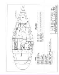
<strong>38</strong> BOW THRUSTER Page 1 of 6 (1-23-2006 Update)1. The bow thruster will be located in under the v-berth bunk, the pan is molded for the bowthruster tube to be located there.2. Remove the v-berth shelves from the boat by taking out the #10 x 1-1/4” screws. Also removethe cutout in the center divide.3. Drill two 2” holes (one on the forward side, the other on the aft side) in the aft stringer(running athwartship) on the port side of centerline so wires can be run from the bowthruster to the port transducer compartment. The forward hole will be extremely hard todrill once the tube is in place unless you have a large arbor I cut it from the aft side. Put 2”chafe guards around the holes.4. Place a straight edge across the top of the pan flange where the “U” shape is for the bowthruster tube & measure down 3-1/2” at the middle of the “U” (see pictures for clarifiacation.Mark this location, this will be where the center of the tube will go. Do this on boththe port & starboard sides of the boat.5. Drill 6” holes thru the hull at the marked locations so the drill is pointed directly at thecenter of the hole on the other side of the boat, this will make semi-elliptical hole about11” tall & 6” wide.6. Insert the bow thruster tube thru the two holes.7. Once tube is in & level, glass the tube into place on the inside of the boat on both the starboard& port side, make this a thick bond as it will have a 1” radius cut into it from theoutside. On the outside of the boat cut the tube flush with the outside of the hull then put a1” radius along the entire edge of the cutout on both the port & starboard side. Gelcoat thehull & buff.8. Sand & gelcoat the tube & stringer on the inside of the boat as needed.9. Install the bow thruster in the center of the tube, the motor will go on top of the tube.10. Install a 250 amp fuse below the nav seat then install the on/off (isolator) switch in the outboardface forward of the nav seat.11. From the motor route the 1/0 cables (one red 15’, one yellow 17’) port to the hull then aftthru the hanging locker then continue aft thru the PVC pipe under the bunk top to the navstation. Connect the positive cable (red) to the on/off (isolator switch ). Connect the 18”positive (red) cable to the other side of the isolator switch the connect the other end of thiscable to the fuse that was installed earlier under the nav seat. Connect the 30” 1/0 positive(red) cable to the other side of this fuse & connect the other end of the cable to the batteryside of the existing fuse under the battery selection panels. Connect the 1/0 negative(yellow) cable to the negative buss bar under the nav seat.12. Connect cables at the bow thruster unit & route control cable aft thru two new holes (theywill have to be drilled with 2” hole saw then install chafe guards) in the athwartshipstringer to the knot & depth compartment then continue thru pipe to cockpit then up tosteering pedestal.
<strong>38</strong> BOW THRUSTER Page 2 of 61/0 Cables going from bow thruster motor to port sideof boat & aft thru hanging locker.Cables continuing aft thru hanging locker.Cables continuing thru PVC pipe under the bunk top,the PVC pipe only runs halfway under the bunk.Cables continuing under the bunk top, the PVC pipe.Location of isolator switch that will need to be installedon outboard face forward of nav seat.Location of 250 amp fuse that will need to be installed.
<strong>38</strong> BOW THRUSTER Page 3 of 6Location of exist negative buss bar on aft wall in thecompartment under the nav seat. Arrow is pointing tothe negative cable from the bow thruster motor.
<strong>38</strong> BOW THRUSTER Page 4 of 6FWDFWDFWDBond the tube to hull , apply 2 layers of bi-ply2415 around the tube where by hull droughtFWD
<strong>38</strong> BOW THRUSTER Page 5 of 6Apply fiberglass chop (resin to catalyst ratio 2%) to fill fwd of hull cutout from overboard and the glass chopneed to create a radius 15% of bow thruster tube diameter, to minimize noise during bow thruster operation.Glass chop should applied to both port side and starboard side fwd radii of the tube ends.Sand rough glass and patching port and starboard side to perform fwd tube radius of 15% diameter of the tube,then dust off the area and apply <strong>Hunter</strong> white exterior gelcoat on this area.
<strong>38</strong> BOW THRUSTER Page 6 of 6INSTALLATION INSTRUCTIONS FROM MANUFACTURERS MANUAL140 TT model: Installing hub unit1. Place gasket on hub and locate through center hole.2. Apply zinc chromate paste or marine grease to location bore and assemble saddle onto hub (sicoflex orsimilar maybe used to seal saddle in place). Apply blue loctite to bolts and hand tighten along with suppliedwashers.3. Assemble anode kit and propeller in this order:- large washer, propeller, anode, small washer and nyloc nutonto propeller shaft.4. Tighten hub/saddle bolts to 9Nm (6.6lbs.ft). Check that propeller is centered and free turning (within 10minutes of applying Blue Loctite).5. Tighten prop nut to 10Nm (7.4lbs.ft) 140TT, a length of wood placed between prop blade and tunnel willstop movement.NOTE: Poor internal tunnel surface could cause leakage. Apply sealant to this area and gasket if in doubt.6. Antifoul bronze hub.