operating instructions for high voltage motor ... - Metron Eledyne
operating instructions for high voltage motor ... - Metron Eledyne
operating instructions for high voltage motor ... - Metron Eledyne

You also want an ePaper? Increase the reach of your titles
YUMPU automatically turns print PDFs into web optimized ePapers that Google loves.
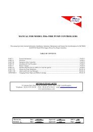
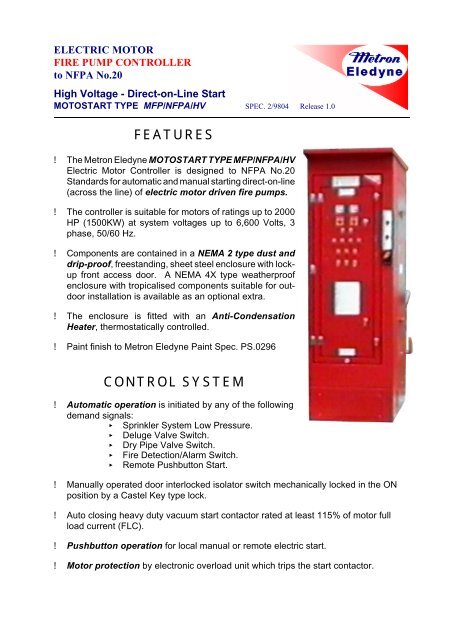
ELECTRIC MOTOR<br />
FIRE PUMP CONTROLLER<br />
to NFPA No.20<br />
High Voltage - Direct-on-Line Start<br />
MOTOSTART TYPE MFP/NFPA/HV SPEC. 2/9804 Release 1.0<br />
FEATURES<br />
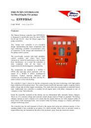
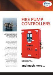
! The <strong>Metron</strong> <strong>Eledyne</strong> MOTOSTART TYPE MFP/NFPA/HV<br />
Electric Motor Controller is designed to NFPA No.20<br />
Standards <strong>for</strong> automatic and manual starting direct-on-line<br />
(across the line) of electric <strong>motor</strong> driven fire pumps.<br />
! The controller is suitable <strong>for</strong> <strong>motor</strong>s of ratings up to 2000<br />
HP (1500KW) at system <strong>voltage</strong>s up to 6,600 Volts, 3<br />
phase, 50/60 Hz.<br />
! Components are contained in a NEMA 2 type dust and<br />
drip-proof, freestanding, sheet steel enclosure with lockup<br />
front access door. A NEMA 4X type weatherproof<br />
enclosure with tropicalised components suitable <strong>for</strong> outdoor<br />
installation is available as an optional extra.<br />
! The enclosure is fitted with an Anti-Condensation<br />
Heater, thermostatically controlled.<br />
! Paint finish to <strong>Metron</strong> <strong>Eledyne</strong> Paint Spec. PS.0296<br />
CONTROL SYSTEM<br />
! Automatic operation is initiated by any of the following<br />
demand signals:<br />
< Sprinkler System Low Pressure.<br />
< Deluge Valve Switch.<br />
< Dry Pipe Valve Switch.<br />
< Fire Detection/Alarm Switch.<br />
< Remote Pushbutton Start.<br />
! Manually operated door interlocked isolator switch mechanically locked in the ON<br />
position by a Castel Key type lock.<br />
! Auto closing heavy duty vacuum start contactor rated at least 115% of <strong>motor</strong> full<br />
load current (FLC).<br />
! Pushbutton operation <strong>for</strong> local manual or remote electric start.<br />
! Motor protection by electronic overload unit which trips the start contactor.
! Normal setting at 300% of <strong>motor</strong> FLC with long delay trip time in excess of 60<br />
seconds.<br />
! Stalled rotor protection with definite trip time 20 seconds. (Max.) At 600% of<br />
<strong>motor</strong> FLC.<br />
! Short circuit protection by High Voltage HRC Fuses with instantaneous rupture at<br />
1200% of <strong>motor</strong> FLC.<br />
! Mains failure protection trips the start contactor if one or more phases become<br />
disconnected.<br />
! Manually operated pushbutton “Stop” control standard. “Autostop” control optional.<br />
! All wiring terminates at clearly marked connector rail. External cable connections<br />
through free-standing plinth.<br />
Facia Mounted:<br />
CONTROL AND INSTRUMENTATION<br />
Isolator <strong>operating</strong> Lever - Castel Key Lock.<br />
Manual Electric Start Pushbutton.<br />
Stop/Reset Pushbutton.<br />
Line Current Ammeter with Phase Selector Switch.<br />
Line to Line Voltmeter and selector switch.<br />
Mains Phases Healthy Indicator Lamps.<br />
Control Circuit Healthy Indicator Lamp.<br />
Pump On Demand Indicator Lamp.<br />
Pump Running Indicator Lamp.<br />
Pump Failed to Start Indicator Lamp.<br />
Pressure Switch (Adjustable Setting) <strong>for</strong> automatic start.<br />
Operating Instructions and Warning Labels.<br />
Remote Alarm-Volt-free Changeover Contacts:<br />
Mains Failure. Pump Running.<br />
Pump on Demand. System Fault.<br />
Phase Sequence Start.
Size/Weight:<br />
Height Width Depth Weight<br />
2300 mm 735 mm 1250 mm 620 Kgms<br />
METRON ELEDYNE LTD<br />
18 AUTUMN PARK, DYSART ROAD, GRANTHAM, NG31 7DD<br />
E-MAIL: INFO@METRONELEDYNE.CO.UK<br />
TELEPHONE +44 (0)1476 516120<br />
FAX +44 (0)1476 516121
<strong>Metron</strong> <strong>Eledyne</strong> OP 20502-01 Iss 1 17.08.98<br />
1 CAUTION<br />
OPERATING INSTRUCTIONS FOR<br />
HIGH VOLTAGE MOTOR CONTROLLER<br />
In order to avoid risk of personal INJURY or damage to the control equipment, READ<br />
THIS MANUAL VERY CAREFULLY. If after reading these <strong>instructions</strong> doubt exists, do<br />
not hesitate to contact <strong>Metron</strong> <strong>Eledyne</strong> <strong>for</strong> further clarification. In the interests of safety<br />
pay special attention to the CAUTION notes listed below:<br />
If work has to be carried out on the <strong>motor</strong> or control equipment, ensure the control<br />
equipment is ISOLATED AND LOCKED OFF from the A.C mains supply be<strong>for</strong>e work<br />
commences. If possible use a temporary label which draws attention to this fact. Label<br />
suggestion: Caution ENGINEER WORKING ON EQUIPMENT.<br />
The control system may start the <strong>motor</strong> at any time. Ensure all concerned are aware<br />
of this condition by means of an appropriate label, prominently displayed in the <strong>motor</strong><br />
area. Label suggestion: WARNING MOTOR MAY START AT ANY TIME.<br />
In order to avoid the risk of serious electric shock, NEVER attempt to energise the <strong>high</strong><br />
<strong>voltage</strong> system with the access door open. The door interlocking mechanism is<br />
designed to prevent this occurrence.<br />
If the inner door has to be opened BEWARE of the single phase control circuit supply.<br />
This warning cannot be stressed enough.<br />
2 GENERAL<br />
The <strong>Metron</strong> <strong>Eledyne</strong> Electric Motor Fire Pump Controller type MFP/NFPAW/HV/DOL,<br />
is designed to operate a three phase <strong>high</strong> <strong>voltage</strong> electric <strong>motor</strong>. The system is based<br />
on the requirements of NFPA No 20, <strong>for</strong> across the line starting of electric driven<br />
pumps. The unit is self contained and self monitoring, with volt free outputs to facilitate<br />
remote monitoring.<br />
The control system comprises of the following main components:<br />
A manually operated door interlocked isolator.<br />
Auto-closing vacuum or gas filled contactor with provision <strong>for</strong> manual mechanical<br />
closing <strong>for</strong> emergency starting.<br />
Phase failure and phase sequence monitoring relays.<br />
1
<strong>Metron</strong> <strong>Eledyne</strong> OP 20502-01 Iss 1 17.08.98<br />
The three phases are monitored by Phase Failure (PFR), and Phase Sequence (PSR),<br />
relays which provides visual and remote indication should a phase fault occur. The<br />
adjustment dial located at the top of the PFR unit should be set to the HV trans<strong>for</strong>mer<br />
secondary phase <strong>voltage</strong>, to take into account any <strong>voltage</strong> dips during <strong>motor</strong> starting.<br />
The <strong>operating</strong> speed of the relay on energisation is approximately 200 ms.<br />
The phase sequence is monitored by a Phase Sequence relay which provides visual<br />
and remote indication if the three phase supply is connected to the controller<br />
incorrectly. With the phases connected to the controller correctly, the LED located at<br />
the top of the unit remains unilluminated.<br />
The following terms are defined as:-<br />
Visual. - Pilot lamp, meter or flag.<br />
Volt free. - Remote indicating volt free<br />
changeover contacts.<br />
Standby. - System awaiting an operational<br />
event.<br />
Clear. - Fault condition corrected, controller<br />
in standby.<br />
Generally, <strong>for</strong> simplicity, only changes in status will be mentioned <strong>for</strong> the above.<br />
THROUGHOUT THE TEXT IN TWO COLUMN FORMAT SECTIONS.<br />
The left hand column describes initiative events. The right hand column describes<br />
resultants.<br />
3 MOTOR PROTECTION<br />
Motor protection against over current i.e. Stalled rotor is provided by the 'Overload<br />
Relay' (OLR). The trip system is calibrated in accordance with NFPA No: 20. Short<br />
circuit protection is provided by means of line fuses L1, L2 & L3.<br />
4 SUPPLY CONNECTIONS<br />
IMPORTANT NOTE<br />
Be<strong>for</strong>e making any power connections to the controller ensure that the main and<br />
test isolators are open.<br />
Connect the 'Pump Motor'. Control circuit output terminals<br />
2
<strong>Metron</strong> <strong>Eledyne</strong> OP 20502-01 Iss 1 17.08.98<br />
Connect the HV supply to the input terminals listed below:<br />
Viewed from the rear:-<br />
3<br />
A, B and C.<br />
Phase 1 (Red). Terminal L1 (Right Side of isolator)<br />
Phase 2 (Yellow). Terminal L2 (Centre of isolator)<br />
Phase 3 (Blue). Terminal L3 (Left Side of isolator)<br />
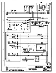
All other connections. As controller circuit diagram.<br />
Control cabinet is securely connected to a<br />
reliable earthing system.<br />
Refer to the cabinet rating label attached to<br />
the top of the front door. Installation parameters are correct.<br />
All system starting and running contacts are<br />
in the <strong>motor</strong> stopped, standby condition.<br />
Set the control circuit timers as follows:<br />
Delay start timer. Set T1 to the desired start delay.<br />
If a start delay is not required. Set the Delay Start timer T1 to<br />
minimum.<br />
Failed To Start. Set T2 to allow the pump ample time<br />
to achieve duty.<br />
Overload timer. T3 Factory set to 1 second.<br />
(False alarm rejection upon<br />
energisation).
<strong>Metron</strong> <strong>Eledyne</strong> OP 20502-01 Iss 1 17.08.98<br />
5 VOLT FREE REMOTE MONITORS<br />
The remote monitor chart below shows the volt free contacts available with this system.<br />
Contacts marked with an asterisk '*' change state on energisation.<br />
DESCRIPTION VOLT FREE CONTACTS OUTPUT TERMINALS<br />
PUMP ON DEMAND RL3/2 5 6 7<br />
PUMP RUNNING RL2/1 8 9 10<br />
DESCRIPTION VOLT FREE CONTACTS OUTPUT TERMINALS<br />
SYSTEM FAULT * RL1/1 11 12 13<br />
MAINS FAILURE * PFR/2 14 15 16<br />
PHASE SEQUENCE PSR/2 17 18 19<br />
FAULT<br />
6 ENERGISING AND DE-ENERGISING<br />
WARNING<br />
DANGER OF ELECTRIC SHOCK<br />
Be<strong>for</strong>e attempting to energise the control system, ensure that all the covers and doors<br />
are securely closed and where applicable, LOCKED.<br />
Refer to the isolator <strong>operating</strong> label attached to the front door.<br />
TO PUT INTO SERVICE<br />
Insert the Castell Key and turn 70 Deg clockwise to expose the Supply Isolator controls.<br />
Obtain the crank handle stowed on the panel behind the front inner door.<br />
Insert the crank handle into the Earthing Switch position and rotate 180 Deg<br />
anti-clockwise. The Red sector on the earthing shaft, marked '1' is visible.<br />
Transfer the crank handle to the Isolator position and rotate 180 Deg clockwise. The<br />
Red sector on the isolator shaft, marked '1' is visible.<br />
Cabinet main front door cannot be opened.<br />
4
<strong>Metron</strong> <strong>Eledyne</strong> OP 20502-01 Iss 1 17.08.98<br />
Visual. Mains Phases Healthy.<br />
Voltmeter reads - red line.<br />
Volt free. System fault.<br />
Remove the crank handle and stow behind the front inner door.<br />
Turn the 'Castell Key' 70 Deg anti-clockwise and remove.<br />
Visual. Mains Phases Healthy.<br />
Control Circuit Healthy.<br />
Voltmeter reads - red line.<br />
Volt free. System fault - clear.<br />
CAUTION<br />
Store the Castell key in a secure place since this is the operator's only means of<br />
gaining access to the isolator controls.<br />
TO REMOVE FROM SERVICE<br />
Refer to the isolator <strong>operating</strong> label attached to the front door.<br />
Obtain the crank handle stowed on the panel behind the front inner door.<br />
Insert the Castell Key and turn 70 Deg clockwise to expose the Supply Isolator controls.<br />
If the main contactor is mechanically latched closed from a previous operation, the<br />
de-latch coil is briefly energised to open the contactor.<br />
Insert the crank handle into the Isolator Switch position and rotate 180 Deg<br />
anti-clockwise. The Green sector on the Isolator shaft, marked 'O' is visible.<br />
Transfer the crank handle to the Earth position and rotate 180 Deg clockwise. The<br />
Green sector on the Earth shaft, marked 'O' is visible. Cabinet main front door can be<br />
opened.<br />
Visual. All Healthy Lights - go out.<br />
Voltmeter reads - Zero.<br />
Volt free. System fault.<br />
Mains failure.<br />
Remove and stow the crank handle. Crank handle clipped to the panel<br />
5
<strong>Metron</strong> <strong>Eledyne</strong> OP 20502-01 Iss 1 17.08.98<br />
Turn the 'Castell Key' fully anti-clockwise<br />
and remove.<br />
CAUTION<br />
6<br />
behind the inner front door.<br />
Store the Castell key in a secure place since this is the operator's only means of<br />
gaining access to the isolator controls.<br />
7 EMERGENCY OPERATION<br />
If the control circuit is faulty but the incoming phases are normal, the <strong>motor</strong> may by<br />
started in an emergency as follows:<br />
Refer to the EMERGENCY START LEVER <strong>operating</strong> label. (Situated next to the start<br />
lever on the cabinet right hand side wall).<br />
To engage the Emergency Start:<br />
Press the Release Button and hold.<br />
Pull the lever quickly in the direction of the arrow.<br />
Release the lever and button.<br />
To disengage the Emergency Start:<br />
Pull the Contactor Mechanical De-latch handle. (Situated to the right of the front door).<br />
8 MANUAL START<br />
Press Manual Start pushbutton. Main contactor latches closed<br />
mechanically.<br />
Motor starts.<br />
Failed To Start timer. Starts to time.<br />
Visual. No Change.<br />
Volt free. Pump on demand.<br />
Pump discharge pressure rises above the<br />
Pump Running pressure switch set point. Pump Running pressure switch<br />
contacts close.<br />
Failed to start timer resets.
<strong>Metron</strong> <strong>Eledyne</strong> OP 20502-01 Iss 1 17.08.98<br />
Visual. Pump Running.<br />
Volt free. Pump running.<br />
Pump on demand.<br />
9 AUTOMATIC OPERATION<br />
STARTING<br />
Main pressure switch falls below the set point. Pressure switch contacts open.<br />
Visual. Pump On Demand<br />
Volt free. Pump on demand.<br />
Delay start timer starts to time.<br />
Delay start timer times out. Main contactor latches closed<br />
mechanically.<br />
Motor starts.<br />
Failed To Start timer. Starts to time.<br />
Pump discharge pressure rises above<br />
Pump Running pressure switch set point. Pump Running pressure<br />
switch contacts close.<br />
Failed To Start timer. Resets.<br />
Visual. Pump Running.<br />
Pump On Demand.<br />
Volt free. Pump running.<br />
Pump on demand.<br />
7<br />
Pump runs on until stopped by the<br />
operator.<br />
Visual. Pump running - goes out.<br />
Pump On Demand - goes out.
<strong>Metron</strong> <strong>Eledyne</strong> OP 20502-01 Iss 1 17.08.98<br />
Volt free. Pump Running - clears.<br />
Pump On Demand - clears.<br />
WARNING<br />
THE MOTOR CANNOT BE STOPPED MANUALLY WHILST A PUMP ON<br />
DEMAND SIGNAL IS PRESENT<br />
PUMP FAILS TO START<br />
Motor contactor closed but running pressure<br />
switch contacts do not close. Pump On Demand indications<br />
established.<br />
8<br />
Failed To Start timer starts to Time.<br />
Failed To Start timer times out.<br />
Visual. Failed To Start.<br />
Volt free. Failed to start.<br />
System fault.<br />
When the system is ready <strong>for</strong> operation,<br />
re-energise the controller.<br />
10 STOPPING THE PUMP<br />
LOCAL STOP<br />
WARNING<br />
THE MOTOR CANNOT BE STOPPED MANUALLY WHILST A PUMP ON<br />
DEMAND SIGNAL IS PRESENT<br />
Press the Stop/Reset button. Motor contactor de-latches<br />
and opens.<br />
Motor stops.<br />
Visual. Pump Running - goes out.<br />
Volt free. Pump running - clear.
<strong>Metron</strong> <strong>Eledyne</strong> OP 20502-01 Iss 1 17.08.98<br />
11 MOTOR CURRENT MONITORING<br />
Set the Ammeter Selector switch to any desired position. Ammeter reads <strong>motor</strong><br />
current flowing in the selected phase lead.<br />
Motor running with more than three times Full Load Current flowing due to any<br />
unspecified fault. Overload unit trips in a time depending upon the degree of<br />
overload in accordance with the NFPA No 20 characteristic.<br />
Motor contactor opens. Motor stops.<br />
Motor contactor cannot re-close<br />
electrically.<br />
Visual. Overload.<br />
Volt free. System Fault.<br />
If Pump On Demand is present, then<br />
Failed To Start occurs.<br />
When the system is ready <strong>for</strong> operation,<br />
re-energise the controller.<br />
NOTE<br />
The overload unit has been factory set to be compatible with the <strong>motor</strong><br />
parameters and the provisions of NFPA No 20. In case of difficulty contact<br />
<strong>Eledyne</strong> Ltd <strong>for</strong> advice. Do not make unauthorized adjustments.<br />
12 PHASE FAULT<br />
PHASE FAILURE<br />
If any phase fails when the <strong>motor</strong> is stationary. Phase Failure Relay trips.<br />
Motor Contactor cannot be<br />
energised.<br />
Visual. Mains Phases Healthy - goes out.<br />
Volt free. System Fault.<br />
Mains failure.<br />
Phase restored. System returns to normal operation<br />
automatically.<br />
9
<strong>Metron</strong> <strong>Eledyne</strong> OP 20502-01 Iss 1 17.08.98<br />
If any phase fails when the <strong>motor</strong> is running. Phase Failure Relay trips.<br />
Motor contactor remains<br />
mechanically latched.<br />
Visual. Pump Running.<br />
Mains Phases Healthy - goes out.<br />
Volt free. Mains failure.<br />
System fault.<br />
Pump running.<br />
10<br />
Motor continues to run until shut<br />
down by either the overload unit or<br />
the operator.<br />
Phase restored. Control system returns normal<br />
operation.<br />
PHASE REVERSAL<br />
If a phase reversal occurs.<br />
Visual. Phase Sequence Fault.<br />
Volt free. Phase sequence fault.<br />
System fault.<br />
Normal <strong>motor</strong> starting is inhibited.<br />
When the phase sequence is correct.<br />
Visual. Phase Sequence Fault - goes out.<br />
Volt free. Phase sequence fault - clear.<br />
System fault - clear.<br />
Normal <strong>motor</strong> starting is available.
<strong>Metron</strong> <strong>Eledyne</strong> OP 20502-01 Iss 1 17.08.98<br />
13 CABINET AND MOTOR HEATERS<br />
Anticondensation Heater Switch on.<br />
With thermostats set to 30EC. Heaters operate<br />
only when the cabinet temperature is below 30EC.<br />
Motor Heater with the <strong>motor</strong> stopped. Motor heater on.<br />
Motor Heater with the <strong>motor</strong> running. Motor heater off.<br />
14 TEST SUPPLY<br />
Main Isolator Closed. Test Supply continuous.<br />
Main Isolator Open. High <strong>voltage</strong> off.<br />
Test Supply available only when the<br />
Test Isolator is On.<br />
With the <strong>high</strong> <strong>voltage</strong> off, the control<br />
circuit may be tested using the Test Supply.<br />
Close the Test Isolator Key Switch.<br />
Open the inner front door and set the<br />
Test/Normal switch to Test.<br />
Visual. Voltmeter reads - zero.<br />
Mains Phases Healthy - out.<br />
Control Circuit Healthy.<br />
Volt free. Mains failure.<br />
System fault - clear.<br />
(PFR bypassed)<br />
11<br />
Motor control logic can be tested<br />
without running the <strong>motor</strong>.
<strong>Metron</strong> <strong>Eledyne</strong> OP 20502-01 Iss 1 17.08.98<br />
ABNORMAL OPERATION<br />
UNDER ABNORMAL CONDITIONS, it is possible to use the test supply to power<br />
the control circuit with the <strong>high</strong> <strong>voltage</strong> on to run the <strong>motor</strong>. This could be done if the<br />
phase monitor trans<strong>for</strong>mer circuit supplying the control <strong>voltage</strong> was faulty, <strong>for</strong><br />
instance.<br />
CAUTION<br />
The above abnormal operation should be attempted only if absolutely necessary<br />
since phase <strong>voltage</strong> monitoring might NOT be available. Overload protection and<br />
current monitoring would be available.<br />
To restore the system to normal, set the<br />
Test/Normal switch to Normal and close<br />
the inner door.<br />
Close the main isolator. The <strong>high</strong> <strong>voltage</strong> is on.<br />
NOTE<br />
The inner door cannot be closed with the Test/Normal switch in the Test position.<br />
12
<strong>Metron</strong> <strong>Eledyne</strong> Division - Tecknit Europe OP 20502-01 Iss 1 17.08.98<br />
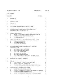
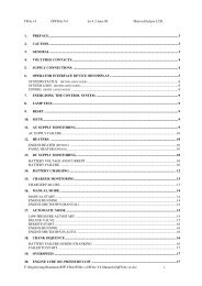
TABLE OF CONTENTS<br />
SECTION PAGE<br />
1 CAUTION 1<br />
2 GENERAL 1<br />
3 MOTOR PROTECTION 2<br />
4 SUPPLY CONNECTIONS 2<br />
5 VOLT FREE REMOTE MONITORS 4<br />
6 ENERGISING AND DE-ENERGISING 4<br />
TO PUT INTO SERVICE 4<br />
TO REMOVE FROM SERVICE 5<br />
7 EMERGENCY OPERATION 6<br />
8 MANUAL START 6<br />
9 AUTOMATIC OPERATION 7<br />
STARTING 7<br />
PUMP FAILS TO START 8<br />
10 STOPPING THE PUMP 8<br />
LOCAL STOP 8<br />
11 MOTOR CURRENT MONITORING 9<br />
12 PHASE FAULT 9<br />
PHASE FAILURE 9<br />
PHASE REVERSAL 10<br />
13 CABINET AND MOTOR HEATERS 11<br />
14 TEST SUPPLY 11<br />
ABNORMAL OPERATION 12
Typical Recommended Consumable Spares<br />
Package <strong>for</strong> Controller Type<br />
MFP/NFPA/HV/3.3KV/350KW<br />
DESCRIPTION STOCK<br />
NO.<br />
QTY UNIT<br />
PRICE<br />
TOTAL<br />
PRICE<br />
Relay, 115V, 2 pole 19278 1 £ 13.12 £ 13.12<br />
Main Phase Fuse TBA 3 £259.80 £779.40<br />
Fuse 3.15A ABWNA 28040 3 £ 76.96 £230.88<br />
Fuse 2A 09034 3 £ 4.18 £ 12.54<br />
Fuse 4A 09035 3 £ 3.94 £ 11.82<br />
Fuse 10A 09037 3 £ 3.94 £ 11.82<br />
Lamp, 6V 0.3A 12021 10 £ 1.43 £ 14.30<br />
<strong>Metron</strong>-<strong>Eledyne</strong> reserve the right, at the time of order placement, to offer an alternative item; on the<br />
understanding the it fulfils the conditions of FIT, FORM and FUNCTION.
Typical Recommended 5-Year Spares<br />
Package <strong>for</strong> Controller Type<br />
MFP/NFPA/HV/3.3KV/350KW<br />
DESCRIPTION STOCK<br />
NO.<br />
QTY UNIT<br />
PRICE<br />
TOTAL<br />
PRICE<br />
Pushbutton ABW110 12115 1 £ 13.21 £ 13.21<br />
Trans<strong>for</strong>mer Lamp 12143 1 £ 27.19 £ 27.19<br />
Ammeter 0-100A 14675 1 £ 47.07 £ 47.07<br />
Thermostat 18022 1 £ 24.38 £ 24.38<br />
Phase Failure Relay PFR501 19071 1 £231.53 £231.53<br />
Overload Relay OLR500 19073 1 £357.83 £357.81<br />
Phase Sequence Relay 19251 1 £291.06 £291.06<br />
Anti-cond. Heater 40W 21153 1 £ 49.32 £ 49.32<br />
Anti-cond. Heater 100W 21157 1 £ 59.19 £ 59.19<br />
Switch, RQ3242 24135 1 £110.67 £110.67<br />
Switch, CT2-MR3-A2 24161 1 £ 27.37 £ 27.27<br />
Switch, N16/EV/O 24437 1 £ 58.89 £ 58.89<br />
Switch, N16/EM/31 24447 1 £ 82.08 £ 82.08<br />
Pushbutton ABW112R 24724 1 £ 27.58 £ 27.58<br />
Keyswitch ASW2K20 24733 1 £ 40.53 £ 40.53<br />
Timer 80018 1 £ 69.67 £ 69.67<br />
Voltmeter 0-3.3KV 80064 1 £127.52 £127.52<br />
<strong>Metron</strong>-<strong>Eledyne</strong> reserve the right, at the time of order placement, to offer an alternative item; on the<br />
understanding the it fulfils the conditions of FIT, FORM and FUNCTION.
Typical Recommended Consumable Spares<br />
Package <strong>for</strong> Controller Type<br />
MFP/NFPA/HV/3.3KV/600KW<br />
DESCRIPTION STOCK NO QTY UNIT PRICE TOTAL PRICE<br />
Relay, 115V, 2 pole 19278 1 £ 13.12 £ 13.12<br />
Main Phase Fuse TBA 3 £281.45 £844.35<br />
Fuse 3.15A ABWNA 28040 3 £ 76.96 £230.88<br />
Fuse 2A 09034 3 £ 4.18 £ 12.54<br />
Fuse 4A 09035 3 £ 3.94 £ 11.82<br />
Fuse 10A 09037 3 £ 3.94 £ 11.82<br />
Lamp, 6V 0.3A 12021 10 £ 1.43 £ 14.30<br />
<strong>Metron</strong>-<strong>Eledyne</strong> reserve the right, at the time of order placement, to offer an alternative item; on the<br />
understanding the it fulfils the conditions of FIT, FORM and FUNCTION.
Typical Recommended 5-Year Spares<br />
Package <strong>for</strong> Controller Type<br />
MFP/NFPA/HV/3.3KV/600KW<br />
DESCRIPTION STOCK<br />
NO.<br />
QTY UNIT<br />
PRICE<br />
TOTAL<br />
PRICE<br />
Pushbutton ABW110 12115 1 £ 13.21 £ 13.21<br />
Trans<strong>for</strong>mer Lamp 12143 1 £ 27.19 £ 27.19<br />
Ammeter 0-100A 14675 1 £ 47.07 £ 47.07<br />
Thermostat 18022 1 £ 24.38 £ 24.38<br />
Phase Failure Relay PFR501 19071 1 £231.53 £231.53<br />
Overload Relay OLR500 19073 1 £357.83 £357.81<br />
Phase Sequence Relay 19251 1 £291.06 £291.06<br />
Anti-cond. Heater 40W 21153 1 £ 49.32 £ 49.32<br />
Anti-cond. Heater 100W 21157 1 £ 59.19 £ 59.19<br />
Switch, RQ3242 24135 1 £110.67 £110.67<br />
Switch, CT2-MR3-A2 24161 1 £ 27.37 £ 27.27<br />
Switch, N16/EV/O 24437 1 £ 58.89 £ 58.89<br />
Switch, N16/EM/31 24447 1 £ 82.08 £ 82.08<br />
Pushbutton ABW112R 24724 1 £ 27.58 £ 27.58<br />
Keyswitch ASW2K20 24733 1 £ 40.53 £ 40.53<br />
Timer 80018 1 £ 69.67 £ 69.67<br />
Voltmeter 0-3.3KV 80064 1 £127.52 £127.52<br />
<strong>Metron</strong>-<strong>Eledyne</strong> reserve the right, at the time of order placement, to offer an alternative item; on the<br />
understanding the it fulfils the conditions of FIT, FORM and FUNCTION.