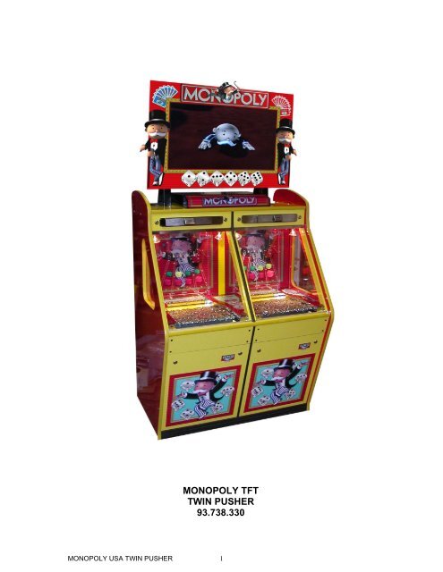
MONOPOLY TFT TWIN PUSHER 93.738.330
MONOPOLY TFT TWIN PUSHER 93.738.330
MONOPOLY TFT TWIN PUSHER 93.738.330

You also want an ePaper? Increase the reach of your titles
YUMPU automatically turns print PDFs into web optimized ePapers that Google loves.
<strong>MONOPOLY</strong> <strong>TFT</strong><strong>TWIN</strong> <strong>PUSHER</strong><strong>93.738.330</strong><strong>MONOPOLY</strong> USA <strong>TWIN</strong> <strong>PUSHER</strong> 1
Table of Contents1. Copyright2. Warranty3. Safety Instructions.3.1 Product Safety3.2 Electrical Safety General3.3 Chemical Safety3.4 Fire Safety3.5 Disposal of Hazardous Components4. Installation Instructions & Daily Checks4.1 General4.2 Physical check4.3 Internal Electrical connections4.4 Electrical Supply4.5 Power Supply Unit4.6 Microprocessor Connections & Functions4.7 Dimensions & Weight4.8 Abbreviations4.9 Daily Checks5. Machine description & Coin prime.5.1 Product Overview5.2 Coin floating<strong>MONOPOLY</strong> USA <strong>TWIN</strong> <strong>PUSHER</strong> 2
Table of Contents6. Operator Adjustments.6.1 Ticket Payout6.2 Tilt6.3 Set Up Menu6.4 Adjustment of Lose Hole size6.5 Playfield Riser6.6 Ticket Dispensers6.7 Universal Hoppers6.8 Lamp Matrix6.9 Switch Matrix6.10 VORTEX Layout6.11 MPU Layout / Plug Locations7. Fault finding guide.7.1 Machine does not work7.2 Pusher motor not running7.3 The tilt does not work7.4 The tilt will not stop7.5 No ticket layout7.6 The halogen lamps do not work8. Machine BOM (including Illustrations)<strong>MONOPOLY</strong> USA <strong>TWIN</strong> <strong>PUSHER</strong> 3
COPYRIGHTThe Jumping Bean Company / Cromptons / Bell-Fruit Games Ltd. / MazoomaGames Ltd. possess exclusive copyright in the SOFTWARE & HARDWAREcontained within this machine. Purchasers have no authority to reproduce any part ofJumping Bean Company / Cromptons. / Bell-Fruit Games Ltd. / Mazooma GamesLtd. software, including copying of EPROMS, unless permission is granted in writing.The Jumping Bean Company / Cromptons. / Bell-Fruit Games Ltd. / MazoomaGames Ltd. also retains various intellectual property rights in the form of LETTERSPATENT, REGISTERED DESIGNS and TRADE MARKS (both in force and pending)applicable to this machine. The purchaser’s right to use these is restricted tooperation of the machine in its original form, or in modified form ONLY IF suchmodifications have been carried out underThe Jumping Bean Company / Cromptons. / Bell-Fruit Games Ltd. / MazoomaGames Ltd. express written licence to do so. Particular note should be taken of anypatent numbers identified within the artwork design or game manual of this machine.Copyright also exists in the ARTWORK DESIGNS for this machine. No part of thisartwork may be reproduced in any way without written authority.The THREE BELLS DEVICE & SCORPION 5 are REGISTERED TRADEMARKSof Bell-Fruit Games Ltd.PERSONS WISHING TO MAKE USE OF ANY OF THE INTELECTUAL PROPERTYABOVE SHOULD CONTACT MAZOOMA GAMES LTD IN THE FIRST INSTANCEEvery effort has been made to ensure that the information contained within thismanual is accurate. Mazooma Games Ltd reserves the right to make alterationswithout prior notice.<strong>MONOPOLY</strong> USA <strong>TWIN</strong> <strong>PUSHER</strong> 4
WARRANTYSeller warrants that its microprocessor unit and parts thereon, are and shall remainfree from defects in material and workmanship under normal use and service for aperiod of six months from date of purchase.Seller warrants that other products or parts thereof shall remain free from defects inmaterial and workmanship under normal use and service for a period of 90 (ninety)days from date of purchase.If the products described in this manual fail to conform to this warranty, seller's soleliability shall be at it's option to repair, replace or credit buyer's account for suchproducts which are returned to seller during said warranty period, provided:a) Seller is promptly notified in writing upon discovery by Buyer that thesaid products are defective.b) Such products are returned prepaid to seller's plant.c) Seller's examination of said products discloses to seller's satisfactionthat such alleged defects existed and were not caused by accident,neglect, alteration, improper repair, installation or improper testing.d) Only seller's recommended or approved electronic components areused as service replacements.In no event shall seller be liable for loss of profits, loss of use, incidental orconsequential damages.Except for any express Warranty set forth in a written Contract between Seller andBuyer which Contract is expressed to supersede the terms of this warranty, allimplied warranties and conditions as to quality or fitness for any particular purposeare hereby expressly excluded.No employee of the Seller has any authority to waive or amend the terms of thiswarranty that shall be deemed accepted by the Buyer on acceptance of the productsreferred to above.ALL WARRANTY CLAIMS FOR THIS MACHINE WILL BE DEALTWITH BY THE BELL-FRUIT GAMES AFTERSALES DEPARTMENT.Tel: 0115 9706707E-MAIL: technical@bellfruitgames.co.uk<strong>MONOPOLY</strong> USA <strong>TWIN</strong> <strong>PUSHER</strong> 5
SAFETY INSTRUCTIONS3.4 Fire SafetyOuter casings of the majority of the components used are made of heatresistant material. Excessive electrical overload conditions may generatesufficient heat to ignite chemical substances within the componentsthemselves or adjacent components, harnesses etc.NOTE:It is imperative that only identical value components are used asreplacements for the original equipment supplied and that correctpolarity of assembly is observed when applicable.Materials that fall into the Fire Hazard category are: -• Chipboard and MDF - releases Formaldehyde vapours when ignited,causes discomfort to the eyes and mucous membranes.• Plastic Laminates - plastic and rubber mouldings, wire insulation etc.,release noxious fumes, which if inhaled may cause irritation dependingon the sensitivity of the individual.• Glass - extreme heat will cause the glass to crack thereby causinginjury.• Electrolytic Capacitors and Batteries - may explode if subjected tofire.• Foamex – flammable.3.5 Disposal of Hazardous ComponentsAs a general rule, electronic components should not be incinerated due to thepossible danger of noxious fumes being released, or components explodingdue to a build up of internal pressures created by expanding gases.<strong>MONOPOLY</strong> USA <strong>TWIN</strong> <strong>PUSHER</strong> 8
INSTALLATION INSTRUCTIONS & DAILY CHECKS4.1 GeneralIt is the policy to ensure that all products are designed, manufactured, testedand released to conform to statutory safety requirements. In support of thispolicy the information contained within this manual is intended as a guide tothe safe installation, reliable working and efficient operation of the machinesupplied.Therefore prior to installation or when servicing, reference to the servicemanual and all WARNING LABELS provided is strongly recommended.Failure to observe any information may result in a safety hazard.CAUTION: Under no circumstances should any major form of installation,repair, adjustment or maintenance be attempted by any other than qualifiedpersonnel.4.2 Physical CheckEnsure that the machine is positioned on a level stable surface and remove allof the transit packaging. Open all doors and check that all parts are secured,electrical connectors are correctly mated and that no components orassemblies have been damaged in transit.4.3 Internal Electrical ConnectorsThe introduction of insulation displacement connectors (IDC) and the use oflighter cables emphasise the need for care when removing and replacingconnectors.When removing connections, pull on the connector and not the wires; whenreplacing connections ensure that (i) the harness housing is being connectedto the correct wafer (ii) the housing is the correctly oriented (Observepositions of polarising pins).<strong>MONOPOLY</strong> USA <strong>TWIN</strong> <strong>PUSHER</strong> 9
INSTALLATION INSTRUCTIONS & DAILY CHECKS4.4 Electrical Supply WARNING: This Apparatus must be EARTHED.Connect the machine to the mains supply (110/120Vac) using an approvedplug. The mains lead is factory fitted to the machine.IMPORTANT: The wires in the mains lead are coloured in accordance withthe following code.GREEN : EARTHWHITE : NEUTRALBLACK : LIVEAs the colours of the wires in the mains lead may not correspond with thecoloured markings identifying the terminals in your plug, proceed as follows.1. EARTH: The wire coloured GREEN must be connected to theterminal marked 'E' or by the safety earth symbol orcoloured GREEN.2. NEUTRAL: The wire coloured WHITE must be connected to theterminal marked 'N'.3. LIVE: The wire coloured BLACK must be connected to theterminal marked 'L'.<strong>MONOPOLY</strong> USA <strong>TWIN</strong> <strong>PUSHER</strong> 10
INSTALLATION INSTRUCTIONS & DAILY CHECKS4.5 Power Supply UnitThe Scorpion 5 power supply consists of a mains switched mode power supplyproviding steady D.C voltages from a mains input supply.The mains input is fed via an IEC plug, mains filter and double pole switch and isprotected by a 5 Amp anti surge fuse.Supply OutputsThe Power Supply outputs are:-a) 44vdc This supply is used for the lamps matrix.b) 24vdc This supply is used for the hoppers.c) 13vdc This supplies the MPU, Coin Acceptor and Reel Mechanism.d) 5vdc This is the I.C. supply on the MPU.e) -12vdc This is the supply for E.D.C unitsPower Supply RemovalTo remove the power unit from the machine disconnect the Power Supplyharness and the earth ring tags from the stud.CAUTION: Extra care should be taken when finally lifting the powersupply from the machine.When replacing the unit ensure that all the earth ring tags are securely fastened tothe stud (identified by means of an earth symbol and that the plug is reconnected<strong>MONOPOLY</strong> USA <strong>TWIN</strong> <strong>PUSHER</strong> 11
INSTALLATION INSTRUCTIONS & DAILY CHECKS4.6 Microprocessor Connections & FunctionsThe microprocessor unit MPU (Designated Scorpion 5 ) is mounted horizontally onthe back panel of the machine. Harnesses to the MPU are generally direct from eachassembly and colour coded. Harnesses are terminated by polarised IDC connectorsof 0.156 and 0.1"pitch.Additional FunctionsReset LED A red LED indicates the state of the system reset. It willilluminate at power up and extinguish after 2 seconds showing that the system resethas taken place. A red button adjacent to the Dil switches resets the MPU (normallyused when bench testing).Game Card The game card has both game and sound proms and should befitted to the 96 way connector Plug Z on the Microprocessor.LED Indicators 7 red LED’s are provided to indicate the presence of thesupplies to the MPU.DIL Switches There are two banks of DIL switches on the MPU board,set horizontally, numbered 1 to 8 from bottom to top, totaling 16 (see diagram).These must be set in the “OFF” position before switching on the machine.<strong>MONOPOLY</strong> USA <strong>TWIN</strong> <strong>PUSHER</strong> 12
INSTALLATION INSTRUCTIONS & DAILY CHECKSMicroprocessor ConnectionsPLUG - FUNCTION CONNECTOR POLARISEDSIZEPINA. - POWER IN. 20way Mini-Fit Jr. N/AB. - CAB SWITCHES. 10way Dual row header. Pin 7.C. - REEL INPUTS. 10way Dual row header. Pin 3.D. - REEL OUTPUTS. 40way Dual row header. Pin 37E. - GAME SWITCHES. 20way Dual row header. Pin 6.F. - L.E.D.s. 34way Dual row header. Pin 18G. - S&P Key. 9way ‘D’ Type Socket. N/AH. - % Key. 9way ‘D’ Type Plug. N/AJ. - LAMPS. 34way Dual row header. Pin 17.K. - REEL LAMPS. 16way Dual row header. Pin 9.L. - GENERAL I/O. 16way Dual row header. Pin 5.M. - AUDIO OUTPUT. 10way Dual row header. Pin 8.N. - ALPHA 1 & 2. 11way 0.1” KK Connector. Pin 3.P. - SEC METER. 7way 0.1” KK Connector. Pin 5.Q. - CCTalk I/F. 10way Dual row header. Pin 6.R. - RS232 PORT 2. 8way 0.1” KK Connector. Pin 6.S. - RS232 PORT 1. 25way ‘D’ Type Plug. N/AT. - HI2 I/F. 10way Dual row header. Pin 9.V. - I2C I/F. 6way 0.1” KK Connector. Pin 3.Z. - GAME CARD. 96 way DIN a+b+c Edge Connector. N/A<strong>MONOPOLY</strong> USA <strong>TWIN</strong> <strong>PUSHER</strong> 13
INSTALLATION INSTRUCTIONS & DAILY CHECKSPLUG A. - POWER IN.20way Mini-Fit Jr. Molex HSG 39-01-2200. Crimp 39-00-0038PIN No. WIRE TYPE & COLOUR DESCRIPTION PIN No. WIRE TYPE & COLOUR DESCRIPTION01 – 24/0.2 Type 2 GRN : +13.5V 11 – n/a : GND02 – 24/0.2 Type 2 GRN : +13.5V 12 – 24/0.2 Type 2 BLK : GND03 – 24/0.2 Type 2 VLT : +44V 13 – 24/0.2 Type 2 BLK : GND04 – 24/0.2 Type 2 VLT : +44V 14 – 24/0.2 Type 2 BLK : GND05 – 24/0.2 Type 2 YLW : +5V 15 – 24/0.2 Type 2 BLK : GND06 – n/a : +5V 16 – 24/0.2 Type 2 BLK : GND07 – 24/0.2 Type 2 RED : +13.5V 17 – 24/0.2 Type 2 BLK : GND08 – 24/0.2 Type 2 RED : +13.5V 18 – 24/0.2 Type 2 BLK : GND09 – 24/0.2 Type 2 BLU : -12V 19 – 24/0.2 Type 2 BLK : GND10 – 24/0.2 Type 2 PNK : +24V 20 – n/a : GNDPLUG C. - REEL INPUTS.10way Dual row header Polarised Pin 3. Molex HSG 90142-0010. Crimp 90119-0109.PIN No. WIRE TYPE & COLOUR DESCRIPTION PIN No. WIRE TYPE & COLOUR DESCRIPTION01 – n/a 06 – 7/0.2 Type 2 BLU/YLW : Sacoa Out Pulse Player 202 – n/a 07 – n/a03 – POLARISING KEY. 08 – 7/0.2 Type 2 YLW : Ticket Notch Sensor Player 104 – 7/0.2 Type 2 YLW/BLK : Ticket Notch Sensor Player 2 09 – n/a05 – n/a 10 – 7/0.2 Type 2 BLU : Sacoa Out Pulse Player 1<strong>MONOPOLY</strong> USA <strong>TWIN</strong> <strong>PUSHER</strong> 14
INSTALLATION INSTRUCTIONS & DAILY CHECKSPLUG D. - REEL OUTPUTS.40way Dual row header Polarised Pin 37. Molex HSG 90142-0040. Crimp 90119-0109.PIN No. WIRE TYPE & COLOUR DESCRIPTION PIN No. WIRE TYPE & COLOUR DESCRIPTION01 – n/a : 21 – 7/0.2 Type 2 BLU/WHT : 2 Player Cash In Meter02 – 7/0.2 Type 2 WHT : +13.5V Sacoa / Ticket 2 Player 22 – 7/0.2 Type 2 BLU/RED : 2 Play Cash Out Meter03 – n/a : 23 – 7/0.2 Type 2 BLU/GRN : 2 Player Cash Box04 – n/a : 24 – 7/0.2 Type 2 BLU/BLK : 2 Player Ticket Out05 – n/a : 25 – n/a : 13v Relay Drive 1&2Pl06 – n/a : 26 – n/a :07 – 7/0.2 Type 2 RED : +13.5V Meters 27 – 7/0.2 Type 2 GRN/RED : Flap coil relay 1Player08 – n/a : 28 – 7/0.2 Type 2 GRN/BLU : Flap coil relay 2Player09 – 7/0.2 Type 2 WHT/BLK : 1 Player Ticket Drive 29 – n/a :10 – 7/0.2 Type 2 PNK/RED : 1 Player Sacoa Inhibit 30 – n/a :11 – 7/0.2 Type 2 WHT : 2 Player Ticket Drive 31 – n/a :12 – 7/0.2 Type 2 PNK : 2 Player Sacoa Inhibit 32 – n/a :13 – n/a : 33 – n/a :14 – n/a : 34 – n/a :15 – 7/0.2 Type 2 BLU/WHT : 1 Player Cash In Meter 35 – n/a :16 – 7/0.2 Type 2 BLU/RED : 1 Player Cash Out Meter 36 – n/a :17 – 7/0.2 Type 2 BLU/GRN : 1 Player Cash Box 37 – POLARISING KEY. : n/c18 – 7/0.2 Type 2 BLU/BLK : 1 Player Ticket Out 38 – 7/0.2 Type 2 BLK : 0V Ticket19 – 7/0.2 Type 2 RED : +13.5V Sacoa / Ticket 1Player 39 – n/a :20 – n/a : 40 – 7/0.2 Type 2 BLU : 0V SacoaPLUG E. - GAME SWITCHES.20way Dual row header Polarised Pin 6. Molex HSG 90142-0020. Crimp 90119-0109.PIN No. WIRE TYPE & COLOUR DESCRIPTION PIN No. WIRE TYPE & COLOUR DESCRIPTION01 – 7/0.2 Type 2 ORG/BLK : SWD_0 11 – 7/0.2 Type 2 BLK/GRN : LDS_0402 – 7/0.2 Type 2 ORG/BRN : SWD_1 12 – 7/0.2 Type 2 BLK/BLU : LDS_0503 – 7/0.2 Type 2 ORG/RED : SWD_2 13 – 7/0.2 Type 2 BLK/VLT : LDS_0604 – 7/0.2 Type 2 ORG/YLW : SWD_3 14 – 7/0.2 Type 2 BLK/GRY : LDS_0705 – 7/0.2 Type 2 ORG/GRN : SWD_4 15 – 7/0.2 Type 2 BLK/WHT : LDS_0806 – POLARISING KEY. : n/c 16 – 7/0.2 Type 2 BLK/PNK : LDS_0907 – 7/0.2 Type 2 BLK/BRN : LDS_00 17 – 7/0.2 Type 2 BLK/PNK + BRN : LDS_1008 – 7/0.2 Type 2 BLK/RED : LDS_01 18 – 7/0.2 Type 2 BLK/PNK + RED : LDS_1109 – 7/0.2 Type 2 BLK/ORG : LDS_02 19 – 7/0.2 Type 2 RED : +13.5V10 – 7/0.2 Type 2 BLK/YLW : LDS_03 20 – 7/0.2 Type 2 BLK : GND<strong>MONOPOLY</strong> USA <strong>TWIN</strong> <strong>PUSHER</strong> 15
INSTALLATION INSTRUCTIONS & DAILY CHECKSPLUG M. - AUDIO OUTPUT.10way Dual row header Polarised Pin 8. Molex HSG 90142-0010. Crimp 90119-0109.PIN No. WIRE TYPE & COLOUR DESCRIPTION PIN No. WIRE TYPE & COLOUR DESCRIPTION01 – 7/0.2 Type 2 WHT : AUD_OUT 06 – n/a :02 – 7/0.2 Type 2 BLU : GND_AUDIO 07 – n/a :03 – n/a : 08 – POLARISING KEY. : n/c04 – n/a : 09 – n/a :05 – n/a : 10 – n/a :PLUG N. - ALPHA 1 & 2.11way 0.1” KK Connector Polarised Pin 3. Molex HSG 22-01-2115. Crimp 4809T.PIN No. WIRE TYPE & COLOUR DESCRIPTION PIN No. WIRE TYPE & COLOUR DESCRIPTION01 – 7/0.2 5/CORE A COL.1 : +13.5V 07 – 7/0.2 5/CORE B COL.1 : +13.5V02 – 7/0.2 5/CORE A COL.2 : ACLK1 08 – 7/0.2 5/CORE B COL.2 : ACLK203 – POLARISING KEY. : n/c 09 – 7/0.2 5/CORE B COL.3 : ADAT204 – 7/0.2 5/CORE A COL.3 : ADAT1 10 – 7/0.2 5/CORE B COL.4 : ARST205 – 7/0.2 5/CORE A COL.4 : ARST1 11 – 7/0.2 5/CORE B COL.5+SCN : GND06 – 7/0.2 5/CORE A COL.5+SCN : GNDPLUG Q. - CCTalk I/F.10way Dual row header Polarised Pin 6. Molex HSG 90142-0010. Crimp 90119-0109.PIN No. WIRE TYPE & COLOUR DESCRIPTION PIN No. WIRE TYPE & COLOUR DESCRIPTION01 – 7/0.2 Type 2 WHT : CCTALK Hoppers 06 – POLARISING KEY. : n/c02 – n/a : 07 – n/a :03 – n/a : 08 – n/a :04 – 7/0.2 Type 2 BLK : 0v Hoppers/Ticket Dispense 09 – n/a :05 – n/a : 10 – 7/0.2 Type 2 PNK : +24V HoppersColour Abbreviation key.BLK - Black BRN - Brown RED - Red ORG - OrangeYLW - Yellow GRN - Green BLU - Blue VLT - VioletGRY - Grey WHT - white PNK - Pink SLV - SilverGLD - Gold SCN - Screen<strong>MONOPOLY</strong> USA <strong>TWIN</strong> <strong>PUSHER</strong> 16
INSTALLATION INSTRUCTIONS & DAILY CHECKS4.7 Dimensions Height with Top Display 7’ 6”Height without Top Display 4’ 9”Depth 2’ 7”Width 3’ 5”Weight (inc <strong>TFT</strong> & Surround Assy) 450 lbs (approx)4.7 Abbreviations:• Coin Entry - one or more slots in the coin entry panel where player mayinsert coin of play.• Coin chute - metal chute that guides the coin from coin entry slot to centrepin perspex.• Centre pin perspex - large perspex panel fitted with scatter pins thatguide the coin down onto the pusher pad.• Pusher pad - the moving pad assembly located at the rear of the playfield.• Playfield - flat bed holding the coins to be pushed into the win chute.• Win chute - large metal form located under front edge of playfield to guidefalling coins to the pay tray.4.8 Daily Checks:• Check the machine is clean inside and outside• Check all the lamps are working.• Check pusher pads are moving.• Check coin chutes are clear of any jammed coins or foreign matter.<strong>MONOPOLY</strong> USA <strong>TWIN</strong> <strong>PUSHER</strong> 17
Machine description and Coin prime.This manual refers to the the Scorpion 5 processor Input/Output Allocationsthroughout. Please note thatPosition 1 refers to the Left-hand Bed (looking at the machine from the front)Position 2 refers to the Right-hand Bed (looking at the machine from the front)5.1 Machine Description & Product OverviewThis design utilizes a twin player pusher cabinet with a 32” <strong>TFT</strong> display unit on top.The player uses the sliding coin entry to insert coins on to their respective play-field.Each coin entry has a micro-switch, which detects the coin.The coins falling onto the moving bed are pushed off the play-field. Coins can exiteither via lose chutes either side of the main field, or fall off the front. These“winning” coins fall into the hoppers where they are ‘counted’, before being depositedinto the cash-box.In addition to this game being offered, additional skill comes from the player utilizingthe sliding coin entry to illuminate the 8 “car” or “hat” lamps on their respective pinpanels. With the pin panel illuminated in full, the screen feature is awarded.The screen feature is played on the Monopoly Board. The player piece is movedaround the board and awarded redemption tickets for landing on properties.The screen feature game is terminated when “Go to jail” is awarded.Please note, when the machine is switched on the count hoppers are enabled forapproximately 15 seconds in order to empty them of any coins that may have beendislodged from the playfield. These coins are fed to the cashbox and are recorded onthe cashbox meter.When a player inserts a coin the hopper in the section being played is enabled. Thehopper is enabled for approximately 15 seconds or for 15 seconds after the lastwinning coin counted by the hopper. (Also see TILT section)<strong>MONOPOLY</strong> USA <strong>TWIN</strong> <strong>PUSHER</strong> 18
Machine description and Coin prime.Monitor ShroudMonitorSliding Coin EntriesHalogen PlayfieldLightingPin PanelsPlayfieldsTicket Doors(access to cashboxes)<strong>MONOPOLY</strong> USA <strong>TWIN</strong> <strong>PUSHER</strong> 19
Machine description and Coin prime.5.2 Coin floating.Switch on the machine and make sure all is working correctly.Carefully remove the glass doors and store in a safe position.Spread coins over the playfield and pusher pad in each play section so that there isa build up of coins at the win chute edge.It will be necessary to feed a number of coins through each coin slot to settle theplayfield area ready for play.<strong>MONOPOLY</strong> USA <strong>TWIN</strong> <strong>PUSHER</strong> 20
Operator adjustments6.1 Ticket Payout.Each time a coin is inserted one or more tickets can be dispensed from the ticketdispenser, these are called “mercy ticket”. The operator using the setup menu canset the number of mercy tickets.For each winning coin the ticket dispenser will dispense one or more tickets. Theoperator can adjust the number of tickets dispensed per winning coin.When the ticket dispenser runs out of tickets (or fails to detect tickets beingdispensed due to a fault) a warning lamp on the lower door illuminates and thesoftware makes no further attempt to dispense tickets until the situation is resolvedand the machine reset. The machine still operates and buffers the number of ticketsowed to the player until the empty condition is cleared. (Also see TILT section).6.2 Tilt.There is one slam tilt assembly in each play-section located on the back of eachTicket Dispenser door.This is accessible by removing the relevant ticket dispenser door.This consists of a weighted contact fixed against the door panel surface, designed todetect banging of the cabinet or service door (See figure 2).Figure 2 – Slam tilt contact.<strong>MONOPOLY</strong> USA <strong>TWIN</strong> <strong>PUSHER</strong> 21
Operator adjustmentsThere is one pendulum tilt assembly located inside the top of the cabinet.(See figure 3).Figure 3 - pendulum tilt.If any of the above switches are made during the operation of the machine anaudible alarm is heard. The ticket dispensers are disabled and any pending ticketsare cleared! The top sign illumination is switched off and during the tilt time thehoppers continue to count winning coins to the cash-box.The length of the tilt period is adjustable by the operator (see set up menu below).<strong>MONOPOLY</strong> USA <strong>TWIN</strong> <strong>PUSHER</strong> 22
Operator adjustments6.3 Set UpMenuThe machine is fitted with a test box, comprising of an alphanumeric display andseven switches.BUTTON1BUTTON2ALPHANUMERIC DISPLAYBUTTON BUTTON BUTTON3 4 5BUTTON6BUTTON7The functions of these buttons are:BUTTON 1 = SETUP ENTRY/EXITBUTTON 4 = ENTER/EXIT TESTBUTTON 6 = STEP DOWN THROUGH OPTIONSBUTTON 7 = STEP UP THROUGH OPTIONSThe operator presses and holds down BUTTON1 for 5 seconds to enter the setupmenu.The alphanumeric will show “SETUP MENU IN 5” and count down and then show“SETUP MENU” followed by a confirmation beep. Releasing Button1 will the showthe first setup option.The setup options are:• VOLUME• COIN/SWIPE• MERCY TICKETS• TICKETS/COIN• TILT TIME• TILT VOLUME• ATTRACT TIME• LAMP TESTThe operator can use BUTTON 6 and BUTTON 7 to step through the options whichdisplay there current settings. If the operator wishes to change the setting hepresses BUTTON 4 and then can setup through the possible settings for that option,pressing BUTTON 4 will save the new setting and return to the menu. PressingBUTTON 1 twice will exit the setup menu.<strong>MONOPOLY</strong> USA <strong>TWIN</strong> <strong>PUSHER</strong> 23
Operator adjustmentsNB the operator must use BUTTON7 to save any changes to the options. Thealphanumeric will confirm the change to the option.Currently the options can be set thusVOLUME - 1-100 Minimum/Maximum volumeMERCY TICKETS - 0-10 0 = No Tickets, a max of 10 per coinTICKETS/COIN - 0-10 0 = No Tickets, a max of 10 per coinTILT TIME - 10-30 10-30 seconds in steps of 5 secondsATTRACT TIME - 0-360 Time between OCD sounds (0=disable)LAMP TEST - All lamps on the pin panels flash6.4 Adjustment of “lose” hole size.The “lose” holes are located one each side of the front edge of the play-field, arefactory set. It is not recommended changing this setting. Other lose hole adjustersare within the cash box.6.5 Playfield Riser.Located at the play-field front edge. The angle of the triple riser is set.6.6 Ticket Dispensers. – Scorpion 5 MPU ConnectionsPlease note that the dispenser interface boards (36.045.001) are fitted to the rear ofeach ticket door.Ticket Dispenser Drive Plug D Pin 9Ticket Notch Sensor Plug C Pin 8<strong>MONOPOLY</strong> USA <strong>TWIN</strong> <strong>PUSHER</strong> 24
Operator adjustments6.7 Azkoyen cctalk U+ Hoppers (Payout & Count) – Scorpion 5 MPU ConnectionsCctalk Plug Q Pin 10 volts Plug Q Pin 4+24 volts Plug Q Pin 10Each playing section has• 1 x Serial “COUNT” hopper with passive overflow• 1 x Serial “PAYOUT” hopperCctalk Address 3 Dil Sw 3 ON LH Playing Position Payout HopperCctalk Address 4 Dil Sw 3 ON LH Playing Position Count HopperCctalk Address 5 Dil Sw 3 ON RH Playing Position Payout HopperCctalk Address 6 Dil Sw 3 ON RH Playing Position Count Hopper<strong>MONOPOLY</strong> USA <strong>TWIN</strong> <strong>PUSHER</strong> 25
6.8 Lamp Matrix – Scorpion 5 MPU ConnectionsData 15 Data 14 Data 13 Data 12 Data 11 Data 10 Data 9 Data 8 Data 7 Data 6 Data 5 Data 4 Data 3 Data 2 Data 1 Data 0Strobe 0Strobe 1Strobe 2Strobe 3Strobe 4TopCar2 nd LHTopCarRHBottomCar2 nd LHBottomCarRHTopCar2 nd LHTopCarRHBottomCar2 nd LHBottomCarRHTopCar2 nd LHTopCarRHBottomCar2 nd LHBottomCarRHTopCar2 nd LHTopCarRHBottomCar2 nd LHBottomCarRHTopCarLHTopCar2 nd RHBottomCarLHBottomCar2 nd RHTopCarLHTopCar2 nd RHBottomCarLHBottomCar2 nd RHTopCarLHTopCar2 nd RHBottomCarLHBottomCar2 nd RHTopCarLHTopCar2 nd RHBottomCarLHBottomCar2 nd RHCarTicket OutRED lampStrobe 5Strobe 6Strobe 7Strobe 8Strobe 9Strobe 10Strobe 11Strobe 12TopHat2 nd LHTopHatRHBottomHat2 nd LHBottomHatRHTopHat2 nd LHTopHatRHBottomHat2 nd LHBottomHatRHTopHat2 nd LHTopHatRHBottomHat2 nd LHBottomHatRHTopHat2 nd LHTopHatRHBottomHat2 nd LHBottomHatRHTopHatLHTopHat2 nd RHBottomHatLHBottomHat2 nd RHTopHatLHTopHat2 nd RHBottomHatLHBottomHat2 nd RHTopHatLHTopHat2 nd RHBottomHatLHBottomHat2 nd RHTopHatLHTopHat2 nd RHBottomHatLHBottomHat2 nd RHHatTicket OutRED lampStrobe 13Strobe 14Strobe 15<strong>MONOPOLY</strong> USA <strong>TWIN</strong> <strong>PUSHER</strong> 26
6.9 Switch Matrix – Scorpion 5 MPU ConnectionsPlug M INPUT1 D0 INPUT2 D1 INPUT3 D2 INPUT4 D3 INPUT5 D4pin 1 BLACK pin 2 BLACK pin 3 BLACK pin 4 BLACK pin 5 BLACKStrobe 1 Player 1Coin 1Player 1Coin 2Player 1Coin 3Player 1Coin 4Player 1Slam SwitchStrobe 2 Player 2Coin 1Player 2Coin 2Player 2Coin 3Player 2Coin 4Player 2Slam SwitchStrobe 3 Player 1Front DoorPlayer 2Front DoorTiltStrobe 4Strobe 5Strobe 6Strobe7Strobe 8Strobe 9Strobe 10Strobe 11Strobe 18D 0 D 1 D 2 D 3 D 4On CPU Pin 11 Pin 12 Pin 13 Pin 14Monopoly 32” <strong>TFT</strong>27<strong>TWIN</strong> <strong>PUSHER</strong>
Operator adjustments6.10 Vortex Layout / ConnectionsPower leadUps leadCommslead port1AudioVGA screenMonopoly 32” <strong>TFT</strong>28<strong>TWIN</strong> <strong>PUSHER</strong>
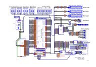
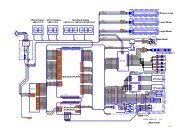
6.11 PLUG LOCATIONSMonopoly 32” <strong>TFT</strong>29<strong>TWIN</strong> <strong>PUSHER</strong>
PLUG BDoor SwitchesMonopoly 32” <strong>TFT</strong>30<strong>TWIN</strong> <strong>PUSHER</strong>
PLUGS C , D and KReelsMonopoly 32” <strong>TFT</strong>31<strong>TWIN</strong> <strong>PUSHER</strong>
PLUG ESwitch InputsPLUG FL.E.D 'sMonopoly 32” <strong>TFT</strong>32<strong>TWIN</strong> <strong>PUSHER</strong>
NEW LAMPS BREAK OUT BOARDMonopoly 32” <strong>TFT</strong>33<strong>TWIN</strong> <strong>PUSHER</strong>
Monopoly 32” <strong>TFT</strong>34<strong>TWIN</strong> <strong>PUSHER</strong>
PLUG MAudioMonopoly 32” <strong>TFT</strong>35<strong>TWIN</strong> <strong>PUSHER</strong>
HOPPER WIRINGMonopoly 32” <strong>TFT</strong>36<strong>TWIN</strong> <strong>PUSHER</strong>
CCTalk WiringMonopoly 32” <strong>TFT</strong>37<strong>TWIN</strong> <strong>PUSHER</strong>
Fault - finding guide.7.1 The machine does not workCheck• Mains wall outlet is switched “on”.• “On/off” switch in play section 1 is switched “on”.• Damage to mains inlet cable.• Power Supply Unit Fuse.7.2 Pusher motor not running.Check• Power Supply Unit Fuse.7.3 The tilt does not work.When the machine is tilted an audible alarm is heard. The ticket dispensers aredisabled and any pending tickets are cleared! The top sign illumination is switchedoff and during the tilt time the hoppers continue to count winning coins to the cashbox.Check• The tilt contacts are not dirty or so far apart they do not to touch when themachine is banged.• The cable connected to every tilt contact ending up at the tilt detects input .7.4 The tilt will not stop.Check• The tilt contacts are not bent together.• The pendulum tilt is operatingMonopoly 32” <strong>TFT</strong>38<strong>TWIN</strong> <strong>PUSHER</strong>
Fault - finding guide.7.5 No ticket pays outCheck• There are tickets at ticket dispenser.• There are no ticket jams.• Electrical connections to ticket dispenser.• Check the center perspex micro switch or loom is all working.• Check the coin count hopper is functioning correctly7.6 The halogen lamps do not work.Check;• The fuses and wiring connections.Monopoly 32” <strong>TFT</strong>39<strong>TWIN</strong> <strong>PUSHER</strong>
Machine BOM (Illustrated)Pin Panel(CAR)91.021.232Pin Panel(HAT)91.021.452Ticket Decal91.021.237Playfield Divider LH Playfield Divider RH91.021.233 91.021.235Playfield Divider Centre91.021.234Door Panel91.021.236Monopoly 32” <strong>TFT</strong>40<strong>TWIN</strong> <strong>PUSHER</strong>
Machine BOMPart Number Description Quantity36045001 Pcba Entropy 2000 Interface 236063002 PCBA Graphic Display Panel (Var brightness) 136205001 Pcba Game Card Scorpion 5 136213001 Pcba Lamp Breakout Scorpion 5 136220001 Pcba Scorpion 5 Mpu New Lamp Circuit 136240001 Pcba Sc 5 Switches Breakout 140051320 M3 X 20mm M/C Screw Countersunk Pozi 2840051410 M4 X 10mm M/C Screw Countersunk Pozi 840053410 M4 X 10mm Hex Head Set Screw Gr 8.8 Bzp 240053420 M4 X 20mm Hex Head Set Screw Gr 8.8 Bzp 240053516 M5 X 16mm Hex Head Set Screw Gr 8.8 440056320 M3 X 20mm Set Screw Pan Head Pozi 4240061512 M5 X 12mm C/Sunk Head Machine Screw 440061612 M6 X 12mm Csk Head Pozi M/C Screw 840085512 M5 X 12mm Pan Head Tamperproof Torx Screw 140131616 M6 X 16mm Hexagon Headed Bolt 440131650 M6 X 50mm Hex Head Bolt 140139050 M5 X 10mm Allen Head Grub Screw 240326 "No.6 X 1/2"" Pan Head" Pozi Self Tap Screw 2040513 "No.6 X 5/8"" Countersunk" Pozi Wood Screw 640620605 No6x1/2 Pan Hd Tamper Proof W/Screw 640626414 No.4x3/4 Rd Hd Pozi Wood Screw 440626610 "No.6 X 3/8"" Pan Head" Pozi Self Tap Screw 241133 Diode In4001 241221 Fuseholder 20 X 5mm Panel Mounted 141685 Heat Shrink Sleeve 641709 45 Deg Angle Spade Terminal Amp 243214050 M5 Spring Washer Singlecoil Square 543214060 M6 Spring Washer 444012066 "P Clip 1/4" 244055095 Cable Clip Self Adhesive9.53mm Brandau Acc-02 444112521 Cable Tie 144mm Long Ea Insuloid Ti8i 748011101 Plastic Rivet 4mm Dia Moss 39158 Or 32517 1548811102 "Lock, Cam & Washer" 248811103 "Lock, Cam & Washer" 249412001 Blind Hole Support Richco 1649412035 Pcb Support Rich Srscbs-M4-12-01 4Monopoly 32” <strong>TFT</strong>41<strong>TWIN</strong> <strong>PUSHER</strong>
Machine BOMPart Number Description Quantity49412036 M4 Hex Nylon Nut Richco Hn-M4-01 449412042 Pcb Support Richco Srlcbs-7-01 649412114 Spacer Self Retaining Richco Ref Ss8-2 249412144 Spacer 6.4mm X 4.5mm I/D Richco Ref Ss8-2 449412228 Barbed Push Fastener Richco Bpf-F4410 1049420028 Hexagon Nylon Spacer G&B Hnp30-A-M3x12mm 651520335 'U' Plus Hopper Medium Bowl Azkoyen 251730011 Fan Terminated Ea110/120v 251900016 Motor 105v 40w 60hz 31rpm Crouzet 806670 152292734 7 Digit Counter Grey12v Oem 652910150 Speaker 4 Ohms Westra Kf120-304 253100009 Entropy 2000 Ticket Dispenser Td-963cr 253713355 Lighting Transformer Tt2317 154000315 4w Distribution Block 154000390 3 Pin Mains Inlet Plug Rs 195-912 454010110 Scotchlok Ug Connector 454761170 11 Way Wafer 4030-11bj .1 Interconnecting 254800050 "Polarising Key 0.1" Molex 0150 4-0292 454861170 11 Way Housing .1 Idc A-7690s C11 38-00-2401 254900211 Fuse 2 Amp 20mm X 5mm Glass Anti Surge 155806302 "Insulating Sleeve 1/4" I/D Amp 154509-44509 355806304 Insulating Boot Type C Mains Filter 256129009 M262 Dichroic Lamp 12v 20w Cool Beam 457330000 Microswitch Otehall Bb1/R-S10 857520010 Push Switch Double Pole Cherry Ue79-6 8a 357611002 Slam Tilt Switch 22-2201-11 26000310 M3 X 10mm Pan Head Pozi Screw 106000410 M4 X 10mm Pan Head Pozi Screw 166000412 M4 X 12mm Pan Head Pozi Screw 46010310 M3 X 10mm Countersunk Head Pozi Screw 362003nn M3 Nyloc Nut 6462004hn M4 Hex Nut 1662004nn M4 Nyloc Nut 1662005hn M5 Hex Nut 562006hn M6 Hex Nut 962103is M3 Shakeproof Washer 662103nd M3 Plain Washer 66Monopoly 32” <strong>TFT</strong>42<strong>TWIN</strong> <strong>PUSHER</strong>
Machine BOMPart Number Description Quantity62104is M4 Shakeproof Washer 862104nd M4 Plain Washer 2662105ld M5 Washer 462106nd M6 Plain Washer 478500006 Mains Filter Schaffner Fn9222r-6-06 190307068 Plate Fan Vent Grill 290307484 Plate Fan Mounting 290442238 Tilt Weight 190442242 Spacer 3690520118 Plate Coin Entry Back 290520175 Base Scorpion 5 Mpu 190520176 Cover Scorpion 5 Mpu 190520177 Plate Scorpion 5 Mpu Cover 190520301 Plate Coin Entry Slide 290520946 Plate Pcb Slot Cover 190520955 Chassis Psu 190520991 Plate Pusher 290520993 Plate Motor Mounting 190520996 Winchute 290521009 Plate Accuride Slide Fixing 490521027 Divider Rundown 190521028 Cashbox 290521032 Tray Coin Entry Trash 290623059 Bezel Coin Entry0.984 Token 290623194 Runners Telescopic Slide Accuride Cz0115-1556u 290623202 Pusher Drive Channel 190623204 Spacer Accuride Slide 190623205 Drive Arm 190623206 Spacer Motor Plate 490623207 Ball Bearing 190623217 Extrusion Glass Door Retainer 290623218 Extrusion Ptfe Retainer 290623374 Weight Wire 190623375 Bracket Tilt Weight Contact Large Brkt 190850316 Bracket Transformer Mounting 190850391 Bracket Hopper Support 290850433 Bracket Coin Deflector 2Monopoly 32” <strong>TFT</strong>43<strong>TWIN</strong> <strong>PUSHER</strong>
Machine BOMPart Number Description Quantity90850513 Bracket Hopper Mounting 290851015 Bracket Single Riser 290851029 Bracket Retainer 290851030 Bracket Coin Door Glass Retaining 290851032 Bracket Cashbox Chute Twin Tft Pusher 290851055 Bracket Perspex Support Bottom 490851056 Bracket Rh Divider Side Plate 290851057 Bracket Lh Divider Side Plate 290851062 Bracket Rundown 290851063 Bracket Halogen Lamp 490851065 Bracket 3 Piece Riser 290857577 Bracket Mech Location 290866632 Bracket Tilt Wire Support Small Brkt 190873610 Bracket Momentary Switch 291010147 Infill Block 491010148 Coin Guide 691010149 Coin Guide Long 491010150 Centre Guide 691010151 Outer Guide 491010209 Front Panel Monopoly Tft 2pp 291010210 Side Strip Monopoly Tft 2pp 491010218 Skimmer Monopoly Tft 2pp 491021232 Car P/Panel Back Perspex Monopoly Tft 2pp 191021233 Playfield Divider Lh Monopoly Tft 2pp 191021234 P'field Divider Centre Monopoly Tft 2pp 191021235 Playfield Divider Rh Monopoly Tft 2pp 191021236 Tckt Door/Side Panel Dec Monopoly Tft 2pp 291021237 Ticket Decal Ea Monopoly Tft 2pp 291021452 Hat P/Panel Back Perspex Monopoly Tft 2pp 191451495 Mpu Insulation Plate 191451542 Side Window Panel 291682506 Slide Block 291682520 Ptfe Block 291682529 Pusher Strip 291771354 Test Box Vac Forming 191771355 Test Box Cover Vac Forming 191802169 Chute Cashbox Twin Tft Pusher 2Monopoly 32” <strong>TFT</strong>44<strong>TWIN</strong> <strong>PUSHER</strong>
Machine BOMPart Number Description Quantity91891333 Grill Fan/Speaker 292752343 'Coin In' Label 192752344 'Ticket Out' Label 192752364 'Winning Coins' Label 192766078 Coin Out Label 192931049 Glass Door2 Player Tft Pusher 294849152 Runner Cashbox Guide 494895081 Tilt Board 196832569 Iec 320 Skt To Iec 320 Plug 2m Lead 296832606 Mains Lead Ul So1.Co2.Eo2.06.B 196832613 Iec Plug To Iec X2 Socket - 507-9860 196861729 200mm Earth Link Ul 196861730 400mm Earth Link Ul 496861731 650mm Earth Link Ul 196861737 Psu Live Link Assy Ul 196861738 Psu Earth Link Assy 150mm Ul 196876119 Hal Lamp Holder Harness Ul 296876367 Lamps Interface Harness Scorpion 5 196876520 Top Box Test Harness 196876783 Tt2317 Transformer Outlet Harness 196877172 Sc 5 To Switch Breakout Harness 196877373 Pc Psu Harness 5 Gaming 196877408 Door Harness 196877454 Main Cabinet Loom Monopoly Tft 2pp 196877455 Halogen Lamp Harness Monopoly Tft 2pp 196877458 Pin Panel Harness Monopoly Tft 2pp 196877488 Fan Harness 196877489 Comms Harness 196912487 Vortex Ps8080 Tower 196941342 Psu Sanken 44volts Mk2 Sps077w-44 197651301 Double Ticket Bin 297854317 Mains Plate & Stud 497953831 Isolating Switch Bracket & Stud 199895209 Cpu Lh Side Panel Assy 199895240 Pusher Panel Assembly 199955170 Cabinet Ga Twin Tft Pusher 1Monopoly 32” <strong>TFT</strong>45<strong>TWIN</strong> <strong>PUSHER</strong>