Diesel Engine Fire Pump Controller Type EFP ... - Metron Eledyne
Diesel Engine Fire Pump Controller Type EFP ... - Metron Eledyne
Diesel Engine Fire Pump Controller Type EFP ... - Metron Eledyne

You also want an ePaper? Increase the reach of your titles
YUMPU automatically turns print PDFs into web optimized ePapers that Google loves.
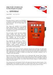
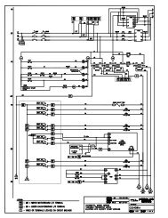
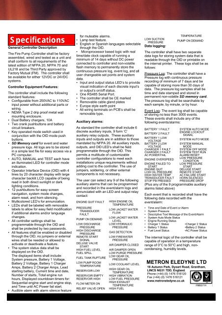
SpecificationsGeneral <strong>Controller</strong> DescriptionThe <strong>Fire</strong> <strong>Pump</strong> <strong>Controller</strong> shall be factoryassembled, wired and tested as a unit andshall conform to all requirements of thelatest edition of NFPA 20, NFPA 70 andUL218 and be Third Party approved byFactory Mutual (FM). The controller shallbe available for either 12VDC or 24VDCsystems.<strong>Controller</strong> Equipment Features:The controller shall include the followingstandard features:• Configurable from 250VAC to 110VACinput power without additional parts orwiring.• NEMA <strong>Type</strong> 2 drip proof metal wallmounting enclosure.• Dual Battery chargers, 10A• Two crank pushbuttons and batterycircuit breakers.• Key operated mode switch used inconjunction with the OID mode pushbuttons.• SD Memory card for event and waterpressure logs. All logs are to be storedin a simple text file for easy access via aPC computer.• AUTO, MANUAL and TEST each havean illuminated LED for controller modeindication.• Operator Interface Device (OID) with 4lines by 20 character display with largecharacter backlit LCD capable of beingread in both direct sunlight or darklighting conditions.• 12 pushbuttons for easy screennavigation, system mode changes,alarm reset, and horn silencing.• Multicolored LED’s for annunciation.• LEDs shall be labeled with removablelabels to allow for easy field modificationif additional alarms and/or languagechanges.• All controller settings shall beprogrammable through the OlD andshall be protected by two passwords.• All features shall be enabled or disabledthrough the OlD, no jumpers or externalwires shall be needed or allowed toactivate or deactivate a feature.• The system status data shall bedisplayed on the OlD.The displayed items shall include:System pressure, Battery 1 Voltage,Battery 2 Voltage, Battery 1 ChargerAmps, Battery 2 Charger Amps, Leadstarting battery, Current time and date,Number of starts, Total engine runhours, Displayed countdown timers for:Sequential engine start and engine stop,and Time until AC Power fail start.• Audible alarm with alarm silence featurefor muteable alarms.• Lamp test feature.• English or Spanish languages selectablethrough the OlD.• Microprocessor based logic with realtime/date clock capable of running aminimum of 14 days without DC powerconnected to controller and non-volatileflash memory to permanently store thecontinuous pressure log, event log, and alluser changeable set points and systemdata.• Input and output status LED’s to providevisual indication of each discrete input’sor output’s on/off status.• One RS485 Serial Port.• The controller shall be CE marked• Removable cable gland plates• Europe style earth point• All wiring terminals on PCB’s shall beremovable type.Auxiliary alarms:As standard the controller shall include 6discrete auxiliary inputs, 9 form ‘C’auxiliary relay outputs. These auxiliaryinputs and outputs are in addition to thosemandated by NFPA 20. All auxiliary inputs,outputs, and OlD LED’s shall be fieldprogrammable through the OlD. Thispermits a multitude of customizablecontroller configurations to meet eachinstallations unique requirements withoutadding cost to the controller. The use ofjumpers, soldering, or other externalcomponents is not necessary.The user can select any 9 of the followingauxiliary alarms that can be programmedand recorded in the event/alarm logs andannunciated with an LED and output relaycontact:ENGINE QUIT FAULTPRESSURETRANSDUCERFAULTPUMP ON DEMANDLOW DISCHARGEPRESSUREHIGH DISCHARGEPRESSUREREMOTE STARTSIGNALDELUGE VALVESTARTHIGH FUEL LEVELFUEL SPILLFUEL TANK RUPTURELOW PUMP ROOMTEMPERATURERESERVOIR LOWRESERVOIR EMPTYRESERVOIR HIGHFLOW METER ONRELIEF VALVE OPENHIGH ENGINE OILTEMPERATURELOW JACKET WATERFLOWLOW JACKET WATERLEVELLOW HYDRAULICPRESSUREGAS DETECTIONLOW FIREWATERPRESSUREAIR DAMPER CLOSEDAIR DAMPER OPENLOW PURGE PRESSURELOW GEAR OILPRESSURELOW COOLANT LEVELHIGH GEAR OILTEMPERATUREHIGH VIBRATIONLOW FUEL PRESSUREHIGH EXHAUSTTEMPERATUREHIGH FUELLOW SUCTIONPRESSUREData logging:TEMPERATUREPUMP ON DEMANDThe controller shall have two separatedata logs for storing system data that isreadable through the OlD or printable onthe internal printer. These logs shall be asfollows:Pressure Log: The controller shall have aPressure log with continuous pressurerecording of minimum of 7 days and becapable of storing more than 30 days ofdata. The pressure log samples shall betime and date stamped and stored inpermanent non-volatile SD memory card.The pressure log shall be searchable byeach sample, by minute, or by hour.Event Log: The event log shall be capableof storing no less than 3000 events.These events shall include any of thefollowing events/alarms:BATTERY 1 FAULTBATTERY 2 FAULTBATTERY 1 LOWVOLTAGEBATTERY 2 LOWVOLTAGECHARGER 1 FAULTCHARGER 2 FAULTAC POWER FAILSYSTEM AUTO MODEENGINE LOCKOUTSIGNALSYSTEM AUTO MODESYSTEM MANUALMODESYSTEM OFF MODESYSTEM TEST RUNALARM RESETENGINE OVERSPEEDLOW PRESSURECONDITIONENGINE FAILED TO LOW PRESSURESTARTSTARTENGINE QUITDELUGE STARTLOW OIL PRESSURE REMOTE STARTHIGH WATER TEMP AC FAILURE STARTTRANSDUCER FAULT HORN SILENCEDSTOP PB PRESSED PRESSURE DROP(Plus any of the 9 programmable auxiliaryalarms listed above)Each event that is recorded shall have thefollowing data recorded with theevent/alarm:• Time and Date of Event or Alarm• System Pressure• Descriptive Text Message of the Event/Alarm• System Auto Mode Status• <strong>Engine</strong> Running Status• Charger 1 Status•Charger 2 Status• Battery 1 Status•Battery 2 Status• Fuel Level Status •AC Power StatusThe internal logic of the controller shall becapable of operation in a temperaturerange of 0°C to 50°C and high, noncondensing,humidity levels.METRON ELEDYNE LTD18 Autumn Park, Dysart Road, Grantham,LINCS NG31 7DD, England.Phone (+44) (0) 1476 516120Fax (+44) (0) 1476 516121www.metroneledyne.co.uk