A review of active filters for power quality improvement ... - IEEE Xplore
A review of active filters for power quality improvement ... - IEEE Xplore
A review of active filters for power quality improvement ... - IEEE Xplore

You also want an ePaper? Increase the reach of your titles
YUMPU automatically turns print PDFs into web optimized ePapers that Google loves.
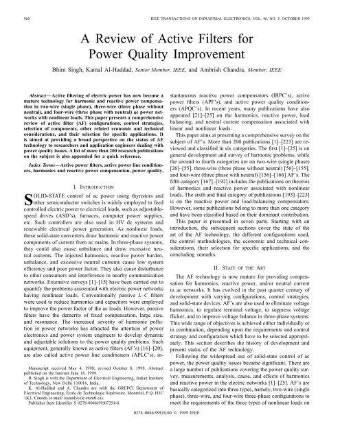
960 <strong>IEEE</strong> TRANSACTIONS ON INDUSTRIAL ELECTRONICS, VOL. 46, NO. 5, OCTOBER 1999A Review <strong>of</strong> Active Filters <strong>for</strong>Power Quality ImprovementBhim Singh, Kamal Al-Haddad, Senior Member, <strong>IEEE</strong>, and Ambrish Chandra, Member, <strong>IEEE</strong>Abstract—Active filtering <strong>of</strong> electric <strong>power</strong> has now become amature technology <strong>for</strong> harmonic and re<strong>active</strong> <strong>power</strong> compensationin two-wire (single phase), three-wire (three phase withoutneutral), and four-wire (three phase with neutral) ac <strong>power</strong> networkswith nonlinear loads. This paper presents a comprehensive<strong>review</strong> <strong>of</strong> <strong>active</strong> filter (AF) configurations, control strategies,selection <strong>of</strong> components, other related economic and technicalconsiderations, and their selection <strong>for</strong> specific applications. Itis aimed at providing a broad perspective on the status <strong>of</strong> AFtechnology to researchers and application engineers dealing with<strong>power</strong> <strong>quality</strong> issues. A list <strong>of</strong> more than 200 research publicationson the subject is also appended <strong>for</strong> a quick reference.Index Terms—Active <strong>power</strong> <strong>filters</strong>, <strong>active</strong> <strong>power</strong> line conditioners,harmonics and re<strong>active</strong> <strong>power</strong> compensation, <strong>power</strong> <strong>quality</strong>.I. INTRODUCTIONSOLID-STATE control <strong>of</strong> ac <strong>power</strong> using thyristors andother semiconductor switches is widely employed to feedcontrolled electric <strong>power</strong> to electrical loads, such as adjustablespeeddrives (ASD’s), furnaces, computer <strong>power</strong> supplies,etc. Such controllers are also used in HV dc systems andrenewable electrical <strong>power</strong> generation. As nonlinear loads,these solid-state converters draw harmonic and re<strong>active</strong> <strong>power</strong>components <strong>of</strong> current from ac mains. In three-phase systems,they could also cause unbalance and draw excessive neutralcurrents. The injected harmonics, re<strong>active</strong> <strong>power</strong> burden,unbalance, and excessive neutral currents cause low systemefficiency and poor <strong>power</strong> factor. They also cause disturbanceto other consumers and interference in nearby communicationnetworks. Extensive surveys [1]–[15] have been carried out toquantify the problems associated with electric <strong>power</strong> networkshaving nonlinear loads. Conventionally passive L–C <strong>filters</strong>were used to reduce harmonics and capacitors were employedto improve the <strong>power</strong> factor <strong>of</strong> the ac loads. However, passive<strong>filters</strong> have the demerits <strong>of</strong> fixed compensation, large size,and resonance. The increased severity <strong>of</strong> harmonic pollutionin <strong>power</strong> networks has attracted the attention <strong>of</strong> <strong>power</strong>electronics and <strong>power</strong> system engineers to develop dynamicand adjustable solutions to the <strong>power</strong> <strong>quality</strong> problems. Suchequipment, generally known as <strong>active</strong> <strong>filters</strong> (AF’s) [16]–[20],are also called <strong>active</strong> <strong>power</strong> line conditioners (APLC’s), in-Manuscript received May 4, 1998; revised October 8, 1998. Abstractpublished on the Internet June 18, 1999.B. Singh is with the Department <strong>of</strong> Electrical Engineering, Indian Institute<strong>of</strong> Technology, New Delhi 110016, India.K. Al-Haddad and A. Chandra are with the GREPCI Department <strong>of</strong>Electrical Engineering, École de Technologie Supérieure, Montréal, P.Q. H3C1K3, Canada (e-mail: kamal@ele.etsmtl.ca).Publisher Item Identifier S 0278-0046(99)07254-8.stantaneous re<strong>active</strong> <strong>power</strong> compensators (IRPC’s), <strong>active</strong><strong>power</strong> <strong>filters</strong> (APF’s), and <strong>active</strong> <strong>power</strong> <strong>quality</strong> conditioners(APQC’s). In recent years, many publications have alsoappeared [21]–[25] on the harmonics, re<strong>active</strong> <strong>power</strong>, loadbalancing, and neutral current compensation associated withlinear and nonlinear loads.This paper aims at presenting a comprehensive survey on thesubject <strong>of</strong> AF’s. More than 200 publications [1]–[223] are <strong>review</strong>edand classified in six categories. The first [1]–[25] is ongeneral development and survey <strong>of</strong> harmonic problems, whilethe second to fourth categories are on two-wire (single phase)[26]–[55], three-wire (three phase without neutral) [56]–[155],and four-wire (three phase with neutral) [156]–[166] AF’s. Thefifth category [167]–[192] includes the publications on theories<strong>of</strong> harmonics and re<strong>active</strong> <strong>power</strong> associated with nonlinearloads. The sixth and final category <strong>of</strong> publications [193]–[223]is on the re<strong>active</strong> <strong>power</strong> and load-balancing compensators.However, some publications belong to more than one categoryand have been classified based on their dominant contribution.This paper is presented in seven parts. Starting with anintroduction, the subsequent sections cover the state <strong>of</strong> theart <strong>of</strong> the AF technology, the different configurations used,the control methodologies, the economic and technical considerations,their selection <strong>for</strong> specific applications, and theconcluding remarks.II. STATE OF THE ARTThe AF technology is now mature <strong>for</strong> providing compensation<strong>for</strong> harmonics, re<strong>active</strong> <strong>power</strong>, and/or neutral currentin ac networks. It has evolved in the past quarter century <strong>of</strong>development with varying configurations, control strategies,and solid-state devices. AF’s are also used to eliminate voltageharmonics, to regulate terminal voltage, to suppress voltageflicker, and to improve voltage balance in three-phase systems.This wide range <strong>of</strong> objectives is achieved either individually orin combination, depending upon the requirements and controlstrategy and configuration which have to be selected appropriately.This section describes the history <strong>of</strong> development andpresent status <strong>of</strong> the AF technology.Following the widespread use <strong>of</strong> solid-state control <strong>of</strong> ac<strong>power</strong>, the <strong>power</strong> <strong>quality</strong> issues became significant. There area large number <strong>of</strong> publications covering the <strong>power</strong> <strong>quality</strong> survey,measurements, analysis, cause, and effects <strong>of</strong> harmonicsand re<strong>active</strong> <strong>power</strong> in the electric networks [1]–[25]. AF’s arebasically categorized into three types, namely, two-wire (singlephase), three-wire, and four-wire three-phase configurations tomeet the requirements <strong>of</strong> the three types <strong>of</strong> nonlinear loads on0278–0046/99$10.00 © 1999 <strong>IEEE</strong>
SINGH et al.: A REVIEW OF ACTIVE FILTERS FOR POWER QUALITY IMPROVEMENT 961supply systems. Single-phase loads, such as domestic lightsand ovens, TV’s, computer <strong>power</strong> supplies, air conditioners,laser printers, and Xerox machines behave as nonlinear loadsand cause <strong>power</strong> <strong>quality</strong> problems. Single-phase (two wire)AF’s are investigated [26]–[55] in varying configurations andcontrol strategies to meet the needs <strong>of</strong> single-phase nonlinearloads. Starting in 1971, many configurations, such as the <strong>active</strong>series filter [48], <strong>active</strong> shunt filter [26]–[47], and combination<strong>of</strong> shunt and series filter [39] have been developed andcommercialized also <strong>for</strong> uninterruptible <strong>power</strong> supply (UPS)applications [50], [52], [53]. Both concepts based on a currentsourceinverter (CSI) with inductive energy storage and avoltage-source inverter (VSI) with capacitive energy storageare used to develop single-phase AF’s.Since major amounts <strong>of</strong> ac <strong>power</strong> are consumed by threephaseloads such as ASD’s with solid-state control. Lately,many ASD systems incorporate AF’s in their front-end design.A substantial number <strong>of</strong> publications have reported on threephasethree wire AF’s [56]–[155], starting in 1976. Activeshunt, <strong>active</strong> series, and combinations <strong>of</strong> both, named as <strong>active</strong><strong>power</strong> <strong>quality</strong> conditioners [138], [152], as well as passive<strong>filters</strong> combined with <strong>active</strong> shunt and <strong>active</strong> series AF’sare some typical configurations used. Many control strategiessuch as instantaneous re<strong>active</strong> <strong>power</strong> theory initially developedby Akagi et al. [63], synchronous frame d–q theory [145],synchronous detection method [143], and notch filter methodare used in the development <strong>of</strong> three-phase AF’s.The problem <strong>of</strong> excessive neutral current [3], [4] is observedin three-phase four-wire systems, mainly due to nonlinear unbalancedloads, such as computer <strong>power</strong> supplies, fluorescentlighting, etc. Resolving the problems <strong>of</strong> neutral current andunbalanced load currents has been attempted in [156]–[166]<strong>for</strong> four-wire systems. These attempts are <strong>of</strong> varying nature,like elimination/reduction <strong>of</strong> neutral current, harmonic compensation,load balancing, re<strong>active</strong> <strong>power</strong> compensation, andcombinations <strong>of</strong> these.A major volume <strong>of</strong> work is reported [167]–[192] on thetheories related to the detection and measurement <strong>of</strong> thevarious quantities, such as real <strong>power</strong>, re<strong>active</strong> <strong>power</strong>, etc.,in the presence <strong>of</strong> harmonics in the supply systems withnonlinear loads. These theories and concepts are quite relevantto extract the control signals <strong>for</strong> AF’s and <strong>for</strong> the development<strong>of</strong> instruments to measure conventional and newly definedquantities in the presence <strong>of</strong> harmonics and unbalance. Forquantifying the effectiveness <strong>of</strong> AF’s, it is important to developgood measuring systems, and these new concepts have givena new impetus to instrumentation technology in this field.The problems <strong>of</strong> re<strong>active</strong> <strong>power</strong> and load unbalance wererecognized long ago, and they became aggravated in thepresence <strong>of</strong> nonlinear loads. Many publications [193]–[223]report on solid-state compensators <strong>for</strong> voltage flicker, re<strong>active</strong><strong>power</strong>, and balancing the nonlinear re<strong>active</strong> loads, such as arcfurnace, traction loads, etc. Many more terminologies, such asstatic var compensators, static flicker compensators, static vargenerators, etc., have been used in the literature.One <strong>of</strong> the major factors in advancing the AF technology isthe advent <strong>of</strong> fast self-commutating solid-state devices. In theinitial stages, thyristors, bipolar junction transistors (BJT’s)Fig. 1.Current-fed-type AF.and <strong>power</strong> MOSFET’s were used <strong>for</strong> AF fabrication; later,static induction thyristors (SIT’s) and gate-turn-<strong>of</strong>f thyristors(GTO’s) were employed to develop AF’s. With the introduction<strong>of</strong> insulated gate bipolar transistors (IGBT’s), the AFtechnology got a real boost and, at present, they are consideredas ideal solid-state devices <strong>for</strong> AF’s. The improved sensortechnology has also contributed to the enhanced per<strong>for</strong>mance<strong>of</strong> the AF. The availability <strong>of</strong> Hall-effect sensors and isolationamplifiers at reasonable cost and with adequate ratings hasimproved the AF per<strong>for</strong>mance.The next breakthrough in AF development has resultedfrom the microelectronics revolution. Starting from the use <strong>of</strong>discrete analog and digital components [162], the progressionhas been to microprocessors, microcontrollers [64], and digitalsignal processors (DSP’s) [50], [148]. Now, it is possible toimplement complex algorithms on-line <strong>for</strong> the control <strong>of</strong> theAF at reasonable cost. This development has made it possibleto use different control algorithms such as, proportionalintegral (P–I) [40], [87], [149], variable-structure control [51],[127], [141], fuzzy logic, and neural nets [46] <strong>for</strong> improvingthe dynamic and steady-state per<strong>for</strong>mance <strong>of</strong> the AF. Withthese <strong>improvement</strong>s, the AF’s are capable <strong>of</strong> providing fastcorrective action, even with dynamically changing nonlinearloads. Moreover, these AF’s are found to compensate quite asum <strong>of</strong> higher order harmonics (typically up to the 25th) [25].III. CONFIGURATIONSAF’s can be classified based on converter type, topology,and the number <strong>of</strong> phases. The converter type can be eitherCSI or VSI bridge structure. The topology can be shunt, series,or a combination <strong>of</strong> both. The third classification is based onthe number <strong>of</strong> phases, such as two-wire (single phase) andthree- or four-wire three-phase systems.A. Converter-Based ClassificationThere are two types <strong>of</strong> converters used in the development<strong>of</strong> AF’s. Fig. 1 shows the current-fed pulsewidth modulation(PWM) inverter bridge structure. It behaves as a nonsinusoidalcurrent source to meet the harmonic current requirement <strong>of</strong>the nonlinear load. A diode is used in series with the selfcommutating device (IGBT) <strong>for</strong> reverse voltage blocking.However, GTO-based configurations do not need the seriesdiode, but they have restricted frequency <strong>of</strong> switching. They
962 <strong>IEEE</strong> TRANSACTIONS ON INDUSTRIAL ELECTRONICS, VOL. 46, NO. 5, OCTOBER 1999Fig. 4.Unified <strong>power</strong> <strong>quality</strong> conditioner as universal AF.Fig. 2.Voltage-fed-type AF.Fig. 3.Series-type AF.are considered sufficiently reliable [68], [79], but have higherlosses and require higher values <strong>of</strong> parallel ac <strong>power</strong> capacitors.Moreover, they cannot be used in multilevel or multistepmodes to improve per<strong>for</strong>mance in higher ratings.The other converter used as an AF is a voltage-fed PWMinverter structure, as shown in Fig. 2. It has a self-supportingdc voltage bus with a large dc capacitor. It has becomemore dominant, since it is lighter, cheaper, and expandable tomultilevel and multistep versions, to enhance the per<strong>for</strong>mancewith lower switching frequencies. It is more popular in UPSbasedapplications, because in the presence <strong>of</strong> mains, the sameinverter bridge can be used as an AF to eliminate harmonics<strong>of</strong> critical nonlinear loads.B. Topology-Based ClassificationAF’s can be classified based on the topology used as seriesor shunt <strong>filters</strong> [48], [106], [115], [121], [146], and unified<strong>power</strong> <strong>quality</strong> conditioners [19], [27], [135], [138], [152] use acombination <strong>of</strong> both. Combinations <strong>of</strong> <strong>active</strong> series and passiveshunt filtering are known as hybrid <strong>filters</strong> [20], [94], [96], [99],[132], [134], [142], [152], [154]. Fig. 2 is an example <strong>of</strong> an<strong>active</strong> shunt filter, which is most widely used to eliminatecurrent harmonics, re<strong>active</strong> <strong>power</strong> compensation (also knownas STATCON), and balancing unbalanced currents. It is mainlyused at the load end, because current harmonics are injected bynonlinear loads. It injects equal compensating currents, oppositein phase, to cancel harmonics and/or re<strong>active</strong> components<strong>of</strong> the nonlinear load current at the point <strong>of</strong> connection. Itcan also be used as a static var generator (STATCON) inthe <strong>power</strong> system network <strong>for</strong> stabilizing and improving thevoltage pr<strong>of</strong>ile.Fig. 3 shows the basic block <strong>of</strong> a stand-alone <strong>active</strong> seriesfilter. It is connected be<strong>for</strong>e the load in series with the mains,Fig. 5.<strong>filters</strong>.Hybrid filter as a combination <strong>of</strong> <strong>active</strong> series and passive shuntusing a matching trans<strong>for</strong>mer, to eliminate voltage harmonics[48], and to balance and regulate the terminal voltage <strong>of</strong> theload or line. It has been used to reduce negative-sequencevoltage and regulate the voltage on three-phase systems [115],[121]. It can be installed by electric utilities to compensatevoltage harmonics and to damp out harmonic propagationcaused by resonance with line impedances and passive shuntcompensators.Fig. 4 shows a unified <strong>power</strong> <strong>quality</strong> conditioner (alsoknown as a universal AF), which is a combination <strong>of</strong> <strong>active</strong>shunt and <strong>active</strong> series <strong>filters</strong> [19], [39], [133], [135], [138],[152]. The dc-link storage element (either inductor [19], [39]or dc-bus capacitor [19], [135]) is shared between two currentsourceor voltage-source bridges operating as <strong>active</strong> series and<strong>active</strong> shunt compensators. It is used in single-phase [19], [39]as well as three-phase configurations [19], [133], [135], [152].It is considered an ideal AF which eliminates voltage andcurrent harmonics and is capable <strong>of</strong> giving clean <strong>power</strong> tocritical and harmonic-prone loads, such as computers, medicalequipment, etc. It can balance and regulate terminal voltageand eliminate negative-sequence currents. Its main drawbacksare its large cost and control complexity because <strong>of</strong> the largenumber <strong>of</strong> solid-state devices involved.Fig. 5 shows the hybrid filter, which is a combination <strong>of</strong>an <strong>active</strong> series filter and passive shunt filter [20], [94], [109],[120], [134], [137], [139], [142], [145], [152], [154]. It is quitepopular because the solid-state devices used in the <strong>active</strong> seriespart can be <strong>of</strong> reduced size and cost (about 5% <strong>of</strong> the load size)and a major part <strong>of</strong> the hybrid filter is made <strong>of</strong> the passiveshunt L–C filter used to eliminate lower order harmonics. Ithas the capability <strong>of</strong> reducing voltage and current harmonics ata reasonable cost. There are many more hybrid configurations[136], [152], [153], but <strong>for</strong> the sake <strong>of</strong> brevity, they are notdiscussed here; however, details can be found in the respectivereferences.
SINGH et al.: A REVIEW OF ACTIVE FILTERS FOR POWER QUALITY IMPROVEMENT 963Fig. 6.Two-wire series AF with current-source converter.Fig. 8. Two-wire unified <strong>power</strong> <strong>quality</strong> conditioner with current-sourceconverter.Fig. 7.Two-Wire shunt AF with current-source converter.C. Supply-System-Based ClassificationThis classification <strong>of</strong> AF’s is based on the supply and/or theload system having single-phase (two wire) and three-phase(three wire or four wire) systems. There are many nonlinearloads, such as domestic appliances, connected to single-phasesupply systems. Some three-phase nonlinear loads are withoutneutral, such as ASD’s, fed from three-wire supply systems.There are many nonlinear single-phase loads distributed onfour-wire three-phase supply systems, such as computers,commercial lighting, etc. Hence, AF’s may also be classifiedaccordingly as two-wire [26]–[55], three-wire [56]–[155], andfour-wire types [156]–[166].1) Two-Wire AF’s: Two-wire (single phase) AF’s [19],[26]–[55] are used in all three modes as <strong>active</strong> series [27],[48], <strong>active</strong> shunt [26]–[38], [40]–[47], [49]–[55], and acombination <strong>of</strong> both as unified line conditioners [19], [27],[39]. Both converter configurations, current-source PWMbridge [19], [27], [38], [39] with inductive energy storageelement and voltage-source PWM bridge [19], [27]–[38],[40]–[55] with capacitive dc-bus energy storage elements,are used to <strong>for</strong>m two-wire AF circuits. In some cases, <strong>active</strong>filtering is included in the <strong>power</strong> conversion stage [36], [40],[41] to improve input characteristics at the supply end.Figs. 6–8 show three configurations <strong>of</strong> <strong>active</strong> series, <strong>active</strong>shunt, and a combination <strong>of</strong> both with current-source bridge,using inductive storage elements. Similar configurations, basedon a VSI bridge, may be obtained by considering only twowires (phase and neutral) at each stage <strong>of</strong> Figs. 2–4. In thecase <strong>of</strong> a series AF with voltage-fed converter, sometimes thetrans<strong>for</strong>mer is removed and load is shunted with passive L–Ccomponents [48]. The series AF is normally used to eliminatevoltage harmonics, spikes, sags, notches, etc., while the shuntAF is used to eliminate current harmonics and re<strong>active</strong> <strong>power</strong>compensation.2) Three-Wire AF’s: Three-phase three-wire nonlinearloads, such as ASD’s, are major applications <strong>of</strong> solid-state<strong>power</strong> converters and, lately, many ASD’s, etc., incorporateAF’s in their front-end design. A large number <strong>of</strong> publications[15]–[20], [56]–[155] have appeared on three-wire AF’swith different configurations. All the configurations shown inFigs. 1–5 are developed, in three-wire AF’s, with three wireson the ac side and two wires on the dc side. Active shuntAF’s are developed in the current-fed type (Fig. 1) or voltagefedtype with single-stage (Fig. 2) or multistep/multileveland multiseries [65], [66], [85], [86] configurations. Activeshunt AF’s are also designed with three single-phase AF’swith isolation trans<strong>for</strong>mers [18] <strong>for</strong> proper voltage matching,independent phase control, and reliable compensation withunbalanced systems. Active series <strong>filters</strong> are developed <strong>for</strong>stand-alone mode (Fig. 3) or hybrid mode with passive shunt<strong>filters</strong> (Fig. 5). The latter (hybrid) has become quite popular[20], [99], [105], [109], [110], [120], [133], [139], [142],[143], [145], [153], [154] to reduce the size <strong>of</strong> <strong>power</strong> devicesand cost <strong>of</strong> the overall system. A combination <strong>of</strong> <strong>active</strong> seriesand <strong>active</strong> shunt is used <strong>for</strong> unified <strong>power</strong> <strong>quality</strong> conditioners(Fig. 4) and universal <strong>filters</strong> [19], [135], [138], [152].3) Four-Wire AF’s: A large number <strong>of</strong> single-phase loadsmay be supplied from three-phase mains with neutral conductor[3], [4], [10], [11]. They cause excessive neutral current,harmonic and re<strong>active</strong> <strong>power</strong> burden, and unbalance. To reducethese problems, four-wire AF’s have been attempted[156]–[166]. They have been developed as: 1) <strong>active</strong> shuntmode with current feed [156] and voltage feed [157], [158],[160], [165]; 2) <strong>active</strong> series mode [163], [165]; and 3)hybrid <strong>for</strong>m with <strong>active</strong> series and passive shunt [164] mode.Figs. 9–11 show three typical configurations <strong>of</strong> shunt AF’s[158]. The first configuration <strong>of</strong> a four-wire shunt AF isknown as the capacitor midpoint type, used in smaller ratings.Here, the entire neutral current flows through dc-bus capacitorswhich are <strong>of</strong> a large value. Fig. 10 shows another configurationknown as the four-pole switch type, in which the fourth poleis used to stabilize the neutral <strong>of</strong> the AF. The three singlephasebridge configuration, shown in Fig. 11, is quite common[157], [159], [162], and this version allows the proper voltage
964 <strong>IEEE</strong> TRANSACTIONS ON INDUSTRIAL ELECTRONICS, VOL. 46, NO. 5, OCTOBER 1999based on control methods [167]–[192] and AF configurations.In the third stage <strong>of</strong> control, the gating signals <strong>for</strong> the solidstatedevices <strong>of</strong> the AF are generated using PWM, hysteresis,sliding-mode, or fuzzy-logic-based control techniques. Thecontrol <strong>of</strong> the AF’s is realized using discrete analog anddigital devices or advanced microelectronic devices, such assingle-chip microcomputers, DSP’s, etc.Fig. 9.Capacitor midpoint four-wire shunt AF.A. Signal ConditioningFor the purpose <strong>of</strong> implementation <strong>of</strong> the control algorithm,several instantaneous voltage and current signals are required.These signals are also useful to monitor, measure, and recordvarious per<strong>for</strong>mance indexes, such as total harmonic distortion(THD), <strong>power</strong> factor, <strong>active</strong> and re<strong>active</strong> <strong>power</strong>, crest factor,etc. The typical voltage signals are ac terminal voltages, dcbusvoltage <strong>of</strong> the AF, and voltages across series elements.The current signals to be sensed are load currents, supplycurrents, compensating currents, and dc-link current <strong>of</strong> theAF. Voltage signals are sensed using either PT’s or Halleffectvoltage sensors or isolation amplifiers. Current signalsare sensed using CT’s and/or Hall-effect current sensors. Thevoltage and current signals are sometimes filtered to avoidnoise problems. The <strong>filters</strong> are either hardware based (analog)or s<strong>of</strong>tware based (digital) with either low-pass, high-pass, orbandpass characteristics.Fig. 10.Fig. 11.Four-pole four-wire shunt AF.Three-bridge four-wire shunt AF.matching <strong>for</strong> solid-state devices and enhances the reliability <strong>of</strong>the AF system. A detailed comparison <strong>of</strong> the features <strong>of</strong> thesethree configurations (Figs. 9–11), is given in [158].IV. CONTROL STRATEGIESControl strategy is the heart <strong>of</strong> the AF and is implementedin three stages. In the first stage, the essential voltage andcurrent signals are sensed using <strong>power</strong> trans<strong>for</strong>mers (PT’s),CT’s, Hall-effect sensors, and isolation amplifiers to gatheraccurate system in<strong>for</strong>mation. In the second stage, compensatingcommands in terms <strong>of</strong> current or voltage levels are derivedB. Derivation <strong>of</strong> Compensating SignalsDevelopment <strong>of</strong> compensating signals either in terms <strong>of</strong>voltages or currents is the important part <strong>of</strong> AF controland affects their rating and transient, as well as steady-stateper<strong>for</strong>mance. The control strategies to generate compensationcommands are based on frequency-domain or time-domaincorrection techniques.1) Compensation in Frequency Domain: Control strategyin the frequency domain is based on the Fourier analysis <strong>of</strong>the distorted voltage or current signals to extract compensatingcommands [50], [56], [60], [64], [74], [81], [88], [92], [97].Using the Fourier trans<strong>for</strong>mation, the compensating harmoniccomponents are separated from the harmonic-polluted signalsand combined to generate compensating commands. Thedevice switching frequency <strong>of</strong> the AF is kept generally morethan twice the highest compensating harmonic frequency <strong>for</strong>effective compensation. The on-line application <strong>of</strong> Fouriertrans<strong>for</strong>m (solution <strong>of</strong> a set <strong>of</strong> nonlinear equations) is acumbersome computation and results in a large response time.2) Compensation in Time Domain: Control methods <strong>of</strong> theAF’s in the time domain are based on instantaneous derivation<strong>of</strong> compensating commands in the <strong>for</strong>m <strong>of</strong> either voltage orcurrent signals from distorted and harmonic-polluted voltageor current signals. There is a large number <strong>of</strong> control methodsin the time domain, which are known as instantaneous “p–q”theory [59], [63], [65], [66], [75], [85], [86], [89], [91],synchronous d–q reference frame method [19], [20], [109],[132], [154], synchronous detection method [157], [159],[162], flux-based controller [144], notch filter method [139],[158], [160], [164], P–I controller [51], [87], [149], slidingmodecontroller [51], [112], [127], [141], etc.
966 <strong>IEEE</strong> TRANSACTIONS ON INDUSTRIAL ELECTRONICS, VOL. 46, NO. 5, OCTOBER 1999widely varying application requirements, such as single-phaseor three-phase, three-wire and four wire systems, requiringcurrent- or voltage-based compensation. Moreover, there is anumber <strong>of</strong> AF configurations which may cater to the needs<strong>of</strong> individual users. A brief list <strong>of</strong> criteria <strong>for</strong> selection <strong>of</strong> anappropriate AF <strong>for</strong> a specific application is discussed in thissection. Table I shows a brief summary <strong>of</strong> selection <strong>of</strong> suitableAF’s <strong>for</strong> specific users.TABLE ISELECTION OF AF’S FOR SPECIFIC APPLICATION CONSIDERATIONSA. Current-Based CompensationCurrent-based compensation is classified as current harmonicscompensation, re<strong>active</strong> <strong>power</strong> compensation, load balancing,and neutral current compensation. This compensation mayeither be required individually or in a combination by theindividual users. For the current harmonics compensation, the<strong>active</strong> shunt filter is an ideal device, but a hybrid <strong>of</strong> <strong>active</strong>series with passive shunt filter is considered most suitablebecause <strong>of</strong> its reduced cost, caused due to the low rating<strong>of</strong> <strong>power</strong> electronics (typically 4%–5% <strong>of</strong> load). Re<strong>active</strong><strong>power</strong> compensation is carried out by using <strong>active</strong> shunt <strong>filters</strong>(similar to a STATCON) <strong>for</strong> adjustable loads and by using accapacitors <strong>for</strong> fixed load. Load balancing in either three-wire orfour-wire systems is generally done by using an <strong>active</strong> shuntfilter configuration. Neutral current compensation is carriedout by employing an <strong>active</strong> shunt filter [161]. For most <strong>of</strong>the combinations <strong>of</strong> these current-based compensations, the<strong>active</strong> shunt filter is technically the right choice, but a hybrid<strong>of</strong> <strong>active</strong> series with passive shunt filter is the most preferablechoice, because <strong>of</strong> the reduced cost <strong>for</strong> the combination <strong>of</strong>these compensation methods.B. Voltage-Based CompensationVoltage-based compensation is categorized as voltage harmonicscompensation, improving voltage regulation, voltagebalancing, voltage flicker reduction, and removing voltagesags and dips. Voltage-based compensation, in general, iscarried out by using <strong>active</strong> series <strong>filters</strong>. However, the voltageflicker is compensated by using the <strong>active</strong> shunt <strong>filters</strong>. Table Ishows a brief summary <strong>of</strong> AF’s <strong>for</strong> compensation in order<strong>of</strong> preference. Nowadays, the AF’s can also correct voltagecompensation <strong>of</strong> momentary voltage dips or sags <strong>of</strong> very shortduration.C. Voltage- and Current-Based CompensationMany applications require a compensation <strong>of</strong> a combination<strong>of</strong> voltage- and current-based problems, a few <strong>of</strong> them beinginterrelated. A hybrid <strong>of</strong> <strong>active</strong> series with <strong>active</strong> shunt <strong>filters</strong>is an ideal choice <strong>for</strong> such mixed compensation. Moreover,this hybrid <strong>of</strong> both AF’s (also known as a unified <strong>power</strong><strong>quality</strong> conditioner, UPQC) is also quite suitable <strong>for</strong> individualcurrent- or voltage-based compensation. However, the rating,size, and cost <strong>of</strong> this UPQC is on the higher side, there<strong>for</strong>e, <strong>for</strong>few combinations <strong>of</strong> compensation such as voltage and currentharmonics, other AF’s (<strong>active</strong> series with passive shunt) areconsidered most suitable. Table I gives brief guidelines <strong>for</strong>the proper selection <strong>of</strong> AF’s suited to the needs <strong>of</strong> individualrequirements. It is only a basic preliminary guide <strong>for</strong> selection<strong>of</strong> suitable AF’s. Since nowadays many industries (ABB,Toshiba, Fuji, Mitsubishi, Westinghouse, etc.) are manufacturingAF’s, more details <strong>for</strong> suitable selection <strong>of</strong> AF’s mayalso be found in their application notes.VIII. CONCLUSIONAn extensive <strong>review</strong> <strong>of</strong> AF’s has been presented to providea clear perspective on various aspects <strong>of</strong> the AF to theresearchers and engineers working in this field. The substantialincrease in the use <strong>of</strong> solid-state <strong>power</strong> control results in harmonicpollution above the tolerable limits. Utilities are findingit difficult to maintain the <strong>power</strong> <strong>quality</strong> at the consumer end,and consumers are paying the penalties indirectly in the <strong>for</strong>m<strong>of</strong> increased plant downtimes, etc. At present, AF technologyis well developed, and many manufacturers [16]–[18] arefabricating AF’s with large capacities. The utilities in the longrun will induce the consumers with nonlinear loads to use theAF’s <strong>for</strong> maintaining the <strong>power</strong> <strong>quality</strong> at acceptable levels. Alarge number <strong>of</strong> AF configurations are available to compensateharmonic current, re<strong>active</strong> <strong>power</strong>, neutral current, unbalancecurrent, and harmonics. The consumer can select the AF with
968 <strong>IEEE</strong> TRANSACTIONS ON INDUSTRIAL ELECTRONICS, VOL. 46, NO. 5, OCTOBER 1999[53] J. C. Wu and H. L. Jou, “A new UPS scheme provides harmonicsuppression, input <strong>power</strong> factor correction,” <strong>IEEE</strong> Trans. Ind. Electron.,vol. 42, pp. 629–635, Dec. 1995.[54] C. Y. Hsu and H. Y. Wu, “A new single-phase <strong>active</strong> <strong>power</strong> filter withreduced energy storage capacitor,” in Proc. <strong>IEEE</strong> PESC’95, 1995, pp.202–208.[55] C. Y. Hsu and H. Y. Wu, “A new single-phase <strong>active</strong> <strong>power</strong> filter withreduced energy storage capacity,” Proc. Inst. Elect. Eng.—Elect. PowerApplicat., vol. 143, no. 1, pp. 25–30, Jan. 1996.[56] A. Ametani, “Harmonic reduction in thyristor converters by harmoniccurrent injection,” <strong>IEEE</strong> Trans. Power App. Syst., vol. 95, pp. 441–449,Mar./Apr. 1976.[57] D. E. Steeper and R. P. Strat<strong>for</strong>d, “Re<strong>active</strong> compensation, harmonicsuppression <strong>for</strong> industrial <strong>power</strong> systems using thyristor converters,”<strong>IEEE</strong> Trans. Ind. Applicat., vol. 12, pp. 232–254, May/June 1976.[58] N. Mohan, H. A. Peterson, W. F. Long, G. R. Dreifuerst, and J. J.Vithayathil, “Active <strong>filters</strong> <strong>for</strong> AC harmonic suppression,” in Proc.<strong>IEEE</strong>-PES Winter Meeting, 1977, pp. 168–174.[59] I. Takahashi and A. Nabae, “Universal <strong>power</strong> distortion compensator<strong>of</strong> line commutated thyristor converter,” in Conf. Rec. <strong>IEEE</strong>-IAS Annu.Meeting, 1980, pp. 858–864.[60] H. Kawahira, T. Nakamura, S. Nakazawa, and M. Nomura, “Active<strong>power</strong> filter,” in Proc. IPEC-Tokyo, 1983, pp. 981–992.[61] S. Miyairi, S. Iida, M. Takimoto, and S. Masukawa, “A new method<strong>of</strong> reducing harmonics in input AC line currents <strong>of</strong> thyristor rectifiercircuit,” in Proc. IPEC-Tokyo, 1983, pp. 993–1004.[62] I. Takahashi, “A flywheel energy storage system having distorted <strong>power</strong>compensation,” in Proc. IPEC-Tokyo, 1983, pp. 1072–1083.[63] H. Akagi, Y. Kanazawa, and A. Nabae, “Instantaneous re<strong>active</strong> <strong>power</strong>compensators comprising switching devices without energy storagecomponents,” <strong>IEEE</strong> Trans. Ind. Applicat., vol. IA-20, pp. 625–630,May/June 1984.[64] K. Hayafune, T. Ueshiba, E. Masada, and Y. Ogiwara, “Microcomputercontrolled <strong>active</strong> <strong>power</strong> filter,” in Proc. <strong>IEEE</strong> IECON’84, 1984, pp.1221–1226.[65] H. Akagi, A. Nabae, and S. Atoh, “Control strategy <strong>of</strong> <strong>active</strong> <strong>power</strong><strong>filters</strong> using multiple voltage-source PWM converters,” <strong>IEEE</strong> Trans. Ind.Applicat., vol. IA-22, pp. 460–465, May/June 1986.[66] H. Akagi, S. Atoh, and A. Nabae, “Compensation characteristics <strong>of</strong><strong>active</strong> <strong>power</strong> filter using multiseries voltage-source PWM converters,”Elect. Eng. Jpn., vol. 106, no. 5, pp. 28–36, 1986.[67] K. Komatsugi and T. Imura, “Harmonic current compensator composed<strong>of</strong> static <strong>power</strong> converter,” in Proc. <strong>IEEE</strong> PESC’86, 1986, pp.283–290.[68] L. Malesani, L. Rossetto, and P. Tenti, “Active filter <strong>for</strong> re<strong>active</strong> <strong>power</strong>,harmonic compensation,” in Proc. <strong>IEEE</strong> PESC’86, 1986, pp. 321–330.[69] T. Nakajima, E. Masada, and Y. Ogihara, “Compensation <strong>of</strong> the cycloconverterinput current harmonics using <strong>active</strong> <strong>power</strong> <strong>filters</strong>,” in Conf.Rec. 2nd EPE Conf., 1987, pp. 1227–1232.[70] M. Kohata, T. Shiota, and S. Atoh, “Compensator <strong>for</strong> harmonics,re<strong>active</strong> <strong>power</strong> using static induction thyristors,” in Conf. Rec. 2nd EPEConf., 1987, pp. 1265–1270.[71] R. Fisher and R. H<strong>of</strong>t, “Three-phase <strong>power</strong> line conditioner <strong>for</strong> harmoniccompensation, <strong>power</strong>-factor correction,” in Conf. Rec. <strong>IEEE</strong>-IAS Annu.Meeting, 1987, pp. 803–807.[72] M. Takeda, K. Ikeda, and Y. Tominaga, “Harmonic current compensationwith <strong>active</strong> filter,” in Conf. Rec. <strong>IEEE</strong>-IAS Annu. Meeting, 1987,pp. 808–815.[73] P. W. Hammond, “A harmonic filter installation to reduce voltagedistortion from static <strong>power</strong> converter,” <strong>IEEE</strong> Trans. Ind. Applicat., vol.24, pp. 53–58, Jan./Feb. 1988.[74] J. H. Choe and M. H. Park, “A new injection method <strong>for</strong> AC harmonicelimination by <strong>active</strong> <strong>power</strong> filter,” <strong>IEEE</strong> Trans. Ind. Electron., vol. 35,pp. 141–147, Feb. 1988.[75] F. Z. Peng, H. Akagi, and A. Nabae, “A novel harmonic <strong>power</strong> filter,”in Proc. <strong>IEEE</strong> PESC’88, 1988, pp. 1151–1159.[76] T. Nakajima, M. Tamura, and E. Masada, “Compensation <strong>of</strong> nonstationaryharmonics using <strong>active</strong> <strong>power</strong> filter with Prony’s spectralestimation,” in Proc. <strong>IEEE</strong> PESC’88, 1988, pp. 1160–1167.[77] A. Nakajima, K. Oku, J. Nishidai, T. Shiraishi, Y. Ogihara, K. Mizuki,and M. Kumazawa, “Development <strong>of</strong> <strong>active</strong> filter with series resonantcircuit,” in Proc. <strong>IEEE</strong> PESC’88, 1988, pp. 1168–1173.[78] M. Takeda, K. Ikeda, A. Teramoto, and T. Aritsuka, “Harmonic current,re<strong>active</strong> <strong>power</strong> compensation with an <strong>active</strong> filter,” in Proc. <strong>IEEE</strong>PESC’88, 1988, pp. 1174–1179.[79] Y. Hayashi, N. Sato, and K. Takahashi, “A novel control <strong>of</strong> a currentsource <strong>active</strong> filter <strong>for</strong> AC <strong>power</strong> system harmonic compensation,” inConf. Rec. <strong>IEEE</strong>-IAS Annu. Meeting, 1988, pp. 837–842.[80] M. Kohata, T. Shiota, Y. Watanabe, S. Atoh, A. Nabae, and Y. Akagi,“A novel compensation using static induction thyristors <strong>for</strong> re<strong>active</strong><strong>power</strong>, harmonics,” in Conf. Rec. <strong>IEEE</strong>-IAS Annu. Meeting, 1988, pp.843–849.[81] G. H. Choe, A. K. Wallace, and M. H. Park, “Control technique <strong>of</strong><strong>active</strong> <strong>power</strong> filter <strong>for</strong> harmonic elimination, re<strong>active</strong> <strong>power</strong> control,” inConf. Rec. <strong>IEEE</strong>-IAS Annu. Meeting, 1988, pp. 859–866.[82] F. Z. Peng, H. Akagi, and A. Nabae, “A new approach to harmonic compensationin <strong>power</strong> systems,” in Conf. Rec. <strong>IEEE</strong>-IAS Annu. Meeting,1988, pp. 874–880.[83] C. Wong, N. Mohan, S. E. Wright, and K. N. Mortensen, “Feasibilitystudy <strong>of</strong> AC, DC-side <strong>active</strong> <strong>filters</strong> <strong>for</strong> HVDC converter terminals,”<strong>IEEE</strong> Trans. Power Delivery, vol. 4, pp. 2067–2075, Oct. 1989.[84] L. T. Moran, P. D. Ziogas, and G. Joos, “Analysis, design <strong>of</strong> a novel3-phase solid-state <strong>power</strong> factor compensator, harmonic suppressorsystem,” <strong>IEEE</strong> Trans. Ind. Applicat., vol. 25, pp. 609–619, July/Aug.1989.[85] F. Z. Peng, H. Akagi, and A. Nabae, “A study <strong>of</strong> <strong>active</strong> <strong>power</strong><strong>filters</strong> using quad-series voltage-source PWM converters <strong>for</strong> harmoniccompensation,” <strong>IEEE</strong> Trans. Power Electron., vol. 5, pp. 9–15, Jan.1990.[86] H. Akagi, Y. Tsukamoto, and A. Nabae, “Analysis, design <strong>of</strong> an <strong>active</strong><strong>power</strong> filter using quad-series voltage source PWM converters,” <strong>IEEE</strong>Trans. Ind. Applicat., vol. 26, pp. 93–98, Jan./Feb. 1990.[87] T. Furuhashi, S. Okuma, and Y. Uchikawa, “A study on the theory <strong>of</strong>instantaneous re<strong>active</strong> <strong>power</strong>,” <strong>IEEE</strong> Trans. Ind. Electron., vol. 37, pp.86–90, Feb. 1990.[88] W. M. Grady, M. J. Samotyj, and A. H. Noyola, “Survey <strong>of</strong> <strong>active</strong><strong>power</strong> line conditioning methodologies,” <strong>IEEE</strong> Trans. Power Delivery,vol. 5, pp. 1536–1542, July 1990.[89] L. Rossetto and P. Tenti, “Using AC-fed PWM converters as instantaneousre<strong>active</strong> <strong>power</strong> compensators,” in Proc. <strong>IEEE</strong> PESC’90, 1990,pp. 855–861.[90] S. Fukuda and M. Yamaji, “Design, characteristics <strong>of</strong> <strong>active</strong> <strong>power</strong> filterusing current source converter,” in Conf. Rec. <strong>IEEE</strong>-IAS Annu. Meeting,1990, pp. 965–970.[91] F. Z. Peng, H. Akagi, and A. Nabae, “A new approach to harmoniccompensation in <strong>power</strong> systems—A combined system <strong>of</strong> shunt passive,series <strong>active</strong> <strong>filters</strong>,” <strong>IEEE</strong> Trans. Ind. Applicat., vol. 26, pp. 983–990,Nov./Dec. 1990.[92] W. M. Grady, M. J. Samotyj, and A. H. Noyola, “Minimizing networkharmonic voltage distortion with an <strong>active</strong> <strong>power</strong> line conditioner,” <strong>IEEE</strong>Trans. Power Delivery, vol. 6, pp. 1690–1697, Oct. 1991.[93] L. Malasani, L. Rossetto, and P. Tenti, “Active <strong>power</strong> filter with hybridenergy storage,” <strong>IEEE</strong> Trans. Power Electron., vol. 6, pp. 392–397, July1991.[94] S. Bhattacharya, D. M. Divan, and B. Banerjee, “Synchronous frameharmonic isolator using <strong>active</strong> series filter,” in Conf. Rec. 4th EPE Conf.,1991, pp. 1230–1240.[95] S. M. Williams and R. G. H<strong>of</strong>t, “Adaptive frequency domain control <strong>of</strong>PWM switched <strong>power</strong> line conditioner,” <strong>IEEE</strong> Trans. Power Electron.,vol. 6, pp. 665–670, Oct. 1991.[96] H. Fujita and H. Akagi, “A practical approach to harmonic compensationin <strong>power</strong> systems-series connection <strong>of</strong> passive, <strong>active</strong> <strong>filters</strong>,”<strong>IEEE</strong> Trans. Ind. Applicat., vol. 27, pp. 1020–1025, Nov./Dec.1991.[97] W. M. Grady, M. J. Samotyj, and A. H. Noyola, “The application<strong>of</strong> network objective functions <strong>for</strong> <strong>active</strong>ly minimizing the impact <strong>of</strong>voltage harmonics in <strong>power</strong> systems,” <strong>IEEE</strong> Trans. Power Delivery, vol.7, pp. 1379–1386, July 1992.[98] B. Acharya, D. M. Divan, and R. W. Gascoigne, “Active <strong>power</strong> <strong>filters</strong>using resonant pole inverters,” <strong>IEEE</strong> Trans. Ind. Applicat., vol. 28, pp.1269–1276, Nov./Dec. 1992.[99] B. B. Banerjee, D. Pileggi, D. Atwood, D. Divan, S. Bhattacharya, andR. Zavadil, “Design <strong>of</strong> an <strong>active</strong> series/passive parallel harmonic filter<strong>for</strong> ASD loads at a wastewater treatment plant,” in Proc. PQA Conf.,1992, pp. 1–7.[100] H. Akagi, “Trends in <strong>active</strong> <strong>power</strong> line conditioners,” in Proc. <strong>IEEE</strong>IECON’92, 1992, pp. 19–24.[101] L. Moran, M. Diaz, V. Higuera, R. Wallace, and J. Dixon, “A threephase<strong>active</strong> <strong>power</strong> filter operating with fixed switching frequency<strong>for</strong> re<strong>active</strong> <strong>power</strong>, current harmonic compensation,” in Proc. <strong>IEEE</strong>IECON’92, 1992, pp. 362–367.[102] E. H. Song and B. H. Kwon, “A novel digital control <strong>for</strong> <strong>active</strong> <strong>power</strong>filter,” in Proc. <strong>IEEE</strong> IECON’92, 1992, pp. 1168–1173.[103] P. F. Wojciak and D. A. Torrey, “The design, implementation <strong>of</strong> <strong>active</strong><strong>power</strong> <strong>filters</strong> based on variable structure system concepts,” in Conf. Rec.<strong>IEEE</strong>-IAS Annu. Meeting, 1992, pp. 850–857.
SINGH et al.: A REVIEW OF ACTIVE FILTERS FOR POWER QUALITY IMPROVEMENT 969[104] A. E. Emanuel and M. Yang, “On the harmonic compensation in nonsinusoidalsystems,” <strong>IEEE</strong> Trans. Power Delivery, vol. 8, pp. 393–399,Jan. 1993.[105] F. Z. Peng, H. Akagi, and A. Nabae, “Compensation characteristics <strong>of</strong>the combined system <strong>of</strong> shunt passive, series <strong>active</strong> <strong>filters</strong>,” <strong>IEEE</strong> Trans.Ind. Applicat., vol. 29, pp. 144–152, Jan./Feb. 1993.[106] V. B. Bhavaraju and P. N. Enjeti, “Analysis, design <strong>of</strong> an <strong>active</strong> <strong>power</strong>filter <strong>for</strong> balancing unbalanced loads,” <strong>IEEE</strong> Trans. Power Electron.,vol. 8, pp. 640–647, Oct. 1993.[107] J. F. Chicharo, D. Dejsakulrit, and B. S. P. Perera, “A centroidbased switching strategy <strong>for</strong> <strong>active</strong> <strong>power</strong> <strong>filters</strong>,” <strong>IEEE</strong> Trans. PowerElectron., vol. 8, pp. 648–653, Oct. 1993.[108] L. Moran, P. Godoy, R. Wallace, and J. Dixon, “A new currentcontrol strategy <strong>for</strong> <strong>active</strong> <strong>power</strong> <strong>filters</strong> using three PWM voltage sourceinverters,” in Proc. <strong>IEEE</strong> PESC’93, 1993, pp. 3–9.[109] S. Bhattacharya, D. M. Divan, and B. B. Banerjce, “Control, reduction<strong>of</strong> terminal voltage total harmonic distortion (THD) in a hybrid series<strong>active</strong>, parallel passive filter system,” in Proc. <strong>IEEE</strong> PESC’93, 1993,pp. 779–786.[110] N. Balbo, D. Sella, R. Penzo, G. Bisiach, D. Cappellieri, L. Malesani,and A. Zuccato, “Hybrid <strong>active</strong> filter <strong>for</strong> parallel harmonic compensation,”in Conf. Rec. EPE Conf., 1993, pp. 133–138.[111] S. Fukuda and J. Endoh, “Control method, characteristics <strong>of</strong> <strong>active</strong><strong>power</strong> <strong>filters</strong>,” in Conf. Rec. EPE Conf., 1993, pp. 139–144.[112] C. Tuttas, “Sliding mode control <strong>of</strong> a voltage-source <strong>active</strong> <strong>filters</strong>,” inConf. Rec. EPE Conf., 1993, pp. 156–161.[113] M. X. Wang, H. Pouliquen, and M. Grandpierre, “Per<strong>for</strong>mance <strong>of</strong> an<strong>active</strong> filter using PWM current source inverter,” in Conf. Rec. EPEConf., 1993, pp. 218–223.[114] J. H. Xu, C. Lott, S. Saadate, and B. Davat, “Compensation <strong>of</strong> AC-DCconverter input current harmonics using a voltage-source <strong>active</strong> <strong>power</strong>filter,” in Conf. Rec. EPE Conf., 1993, pp. 233–238.[115] V. B. Bhavaraju and P. Enjeti, “A novel <strong>active</strong> line conditioner <strong>for</strong> athree-phase system,” in Conf. Rec. <strong>IEEE</strong>-IAS Annu. Meeting, 1993, pp.979–985.[116] J. W. Dixon, J. C. Garcia, and L. T. Moran, “A control system <strong>for</strong>a three-phase <strong>active</strong> <strong>power</strong> filter which simultaneously compensates<strong>power</strong> factor, unbalanced loads,” in Proc. <strong>IEEE</strong> IECON’93, 1993, pp.1083–1087.[117] P. Humberto and Z. C. Albenes, “A simple control strategy <strong>for</strong> shunt<strong>power</strong> line conditioner with inductive energy storage,” in Proc. <strong>IEEE</strong>IECON’93, 1993, pp. 1093–1098.[118] K. H<strong>of</strong>fman and G. Ledwich, “Fast compensation by a pulsed resonantcurrent source <strong>active</strong> <strong>power</strong> filter,” in Proc. <strong>IEEE</strong> IECON’93, 1993, pp.1297–1302.[119] J. N. Le, M. Pereira, K. Renz, and G. Vaupel, “Active damping <strong>of</strong>resonances in <strong>power</strong> systems,” <strong>IEEE</strong> Trans. Power Delivery, vol. 9, pp.1001–1008, Apr. 1994.[120] H. Akagi, “Trends in <strong>active</strong> <strong>power</strong> line conditioners,” <strong>IEEE</strong> Trans.Power Electron., vol. 9, pp. 263–268, May 1994.[121] A. Campos, G. Joos, P. D. Ziogas, and J. F. Lindsay, “Analysis, design<strong>of</strong> a series voltage unbalance compensator based on a three-phase VSIoperating with unbalanced switching functions,” <strong>IEEE</strong> Trans. PowerElectron., vol. 9, pp. 269–274, May 1994.[122] A. Cavallini and G. C. Montanari, “Compensation strategies <strong>for</strong> shunt<strong>active</strong>-filter control,” <strong>IEEE</strong> Trans. Power Electron., vol. 9, pp. 587–593,Nov. 1994.[123] D. Vincenti, H. Jin, and P. Ziogas, “Design, implementation <strong>of</strong> a 25 kVAthree-phase PWM AC line conditioner,” <strong>IEEE</strong> Trans. Power Electron.,vol. 9, pp. 384–389, July 1994.[124] D. Dejsakulrit, B. S. P. Perera, and J. F. Chicharo, “A novel equalsampling switching strategy <strong>for</strong> <strong>active</strong> <strong>power</strong> <strong>filters</strong>,” Elect. Mach.Power Syst., vol. 22, pp. 405–421, Apr. 1994.[125] J. H. Xu, C. Lott, S. Saadate, and B. Davat, “Simulation, experimentation<strong>of</strong> a voltage source <strong>active</strong> filter compensating current harmonics, <strong>power</strong>factor,”in Proc. <strong>IEEE</strong> IECON’94, 1994, pp. 411–415.[126] J. O. Krah and J. Holtz, “Total compensation <strong>of</strong> line side switchingharmonics in converter fed AC locomotives,” in Conf. Rec. <strong>IEEE</strong>-IASAnnu. Meeting, 1994, pp. 913–920.[127] Z. Radulovic and A. Sabanovic, “Active filter control using a slidingmode approach,” in Proc. <strong>IEEE</strong> PESC’94, 1994, pp. 177–182.[128] C. Pahmer, G. A. Capolino, and H. Henao, “Computer-aided design<strong>for</strong> control <strong>of</strong> shunt <strong>active</strong> filter,” in Proc. <strong>IEEE</strong> IECON’94, 1994, pp.669–674.[129] F. Le Magoarou and F. Monteil, “Influence <strong>of</strong> the load on the designprocess <strong>of</strong> an <strong>active</strong> <strong>power</strong> filter,” in Proc. <strong>IEEE</strong> IECON’94, 1994, pp.416–421.[130] P. Verdelho and G. D. Marques, “Design, per<strong>for</strong>mance <strong>of</strong> an <strong>active</strong><strong>power</strong> filter, unbalanced current compensator,” in Proc. <strong>IEEE</strong>IECON’94, 1994, pp. 422–427.[131] G. Ledwich and P. Doulai, “Multiple converter per<strong>for</strong>mance, <strong>active</strong>filtering,” <strong>IEEE</strong> Trans. Power Electron., vol. 10, pp. 273–279, May 1995.[132] S. Bhattacharya, D. M. Divan, and B. B. Banerjee, “Active <strong>filters</strong>olutions <strong>for</strong> utility interface,” in Proc. <strong>IEEE</strong> ISIE’95, 1995, pp. 1–11.[133] A. V. Zyl, J. H. R. Enslin, W. H. Steyn, and R. Spee, “A new unifiedapproach to <strong>power</strong> <strong>quality</strong> management,” in Proc. <strong>IEEE</strong> PESC’95, 1995,pp. 183–188.[134] S. Bhattacharya and D. Divan, “Design, implementation <strong>of</strong> a hybridseries <strong>active</strong> filter system,” in Proc. <strong>IEEE</strong> PESC’95, 1995, pp. 189–195.[135] F. Kamran and T. G. Habetler, “Combined deadbeat control <strong>of</strong> a seriesparallelconverter combination used as a universal <strong>power</strong> filter,” in Proc.<strong>IEEE</strong> PESC’95, 1995, pp. 196–201.[136] N. R. Raju, S. S. Venkata, R. A. Kagalwala, and V. V. Sastry, “An <strong>active</strong><strong>power</strong> <strong>quality</strong> conditioner <strong>for</strong> re<strong>active</strong> <strong>power</strong>, harmonics compensation,”in Proc. <strong>IEEE</strong> PESC’95, 1995, pp. 209–214.[137] Z. Yao, S. Lahaie, and V. Rajagopolan, “Robust compensator <strong>of</strong> harmonics,re<strong>active</strong> <strong>power</strong>,” in Proc. <strong>IEEE</strong> PESC’95, 1995, pp. 215–221.[138] F. Kamran and T. G. Habetler, “A novel on-line UPS with universalfiltering capabilities,” in Proc. <strong>IEEE</strong> PESC’95, 1995, pp. 500–506.[139] M. Rastogi, N. Mohan, and A. A. Edris, “Filtering <strong>of</strong> harmonic currents,damping <strong>of</strong> resonances in <strong>power</strong> systems with a hybrid-<strong>active</strong> filter,” inProc. <strong>IEEE</strong> APEC’95, 1995, pp. 607–612.[140] H. Akagi and H. Fujita, “A new <strong>power</strong> line conditioner <strong>for</strong> harmoniccompensation in <strong>power</strong> systems,” <strong>IEEE</strong> Trans. Power Delivery, vol. 10,pp. 1570–1575, July 1995.[141] S. Saetieo, R. Devaraj, and D. A. Torrey, “The design, implementation<strong>of</strong> a three-phase <strong>active</strong> <strong>power</strong> filter based on sliding mode control,”<strong>IEEE</strong> Trans. Ind. Applicat., vol. 31, pp. 993–1000, Sept./Oct. 1995.[142] M. Rastogi, N. Mohan, and A. A. Edris, “Hybrid-<strong>active</strong> filtering <strong>of</strong>harmonic currents in <strong>power</strong> systems,” <strong>IEEE</strong> Trans. Power Delivery, vol.10, pp. 1994–2000, Oct. 1995.[143] C. E. Lin, W. F. Su, S. L. Lu, C. L. Chen, and C. L. Huang, “Operationstrategy <strong>of</strong> hybrid harmonic filter in demand-side system,” in Conf. Rec.<strong>IEEE</strong>-IAS Annu. Meeting, 1995, pp. 1862–1866.[144] S. Bhattacharya, A. Veltman, D. M. Divan, and R. D. Lorenz, “Fluxbased <strong>active</strong> filter controller,” in Conf. Rec. <strong>IEEE</strong>-IAS Annu. Meeting,1995, pp. 2483–2491.[145] S. Bhattacharya and D. Divan, “Synchronous frame based controllerimplementation <strong>for</strong> a hybrid series <strong>active</strong> filter system,” in Conf. Rec.<strong>IEEE</strong>-IAS Annu. Meeting, 1995, pp. 2531–2540.[146] J. Dixon, G. Venegas, and L. Moran, “A series <strong>active</strong> <strong>power</strong> filter basedon a sinusoidal current controlled voltage source inverter,” in Proc.<strong>IEEE</strong> IECON’95, 1995, pp. 639–644.[147] S. G. Jeong and M. H. Woo, “DSP based <strong>active</strong> <strong>power</strong> filter with predictivecurrent control,” in Proc. <strong>IEEE</strong> IECON’95, 1995, pp. 645–650.[148] Z. Li, H. Jin, and G. Joos, “Control <strong>of</strong> <strong>active</strong> <strong>filters</strong> using digital signalprocessors,” in Proc. <strong>IEEE</strong> IECON’95, 1995, pp. 651–655.[149] H. L. Jou, “Per<strong>for</strong>mance comparison <strong>of</strong> the three-phase <strong>active</strong> <strong>power</strong>filteralgorithms,” Proc. Inst. Elect. Eng.—Generation, Transmission,Distribution, vol. 142, no. 6, pp. 646–652, Nov. 1995.[150] J. W. Dixon, J. J. Garcia, and L. Moran, “Control system <strong>for</strong> three-phase<strong>active</strong> <strong>power</strong> filter which simultaneously compensates <strong>power</strong> factor,unbalanced loads,” <strong>IEEE</strong> Trans. Ind. Electron., vol. 42, pp. 636–641,Dec. 1995.[151] M. Taleb, A. Kamal, A. J. Sowaied, and M. R. Khan, “An alternative<strong>active</strong> <strong>power</strong> filter,” in Proc. <strong>IEEE</strong> PEDES’96, 1996, pp. 410–416.[152] H. Akagi, “New trends in <strong>active</strong> <strong>filters</strong> <strong>for</strong> improving <strong>power</strong> <strong>quality</strong>,”in Proc. <strong>IEEE</strong> PEDES’96, 1996, pp. 417–425.[153] G. H. Rim, I. Kang, W. H. Kim, and J. S. Kim, “A shunt hybrid <strong>active</strong>filter with two passive <strong>filters</strong> in tandem,” in Proc. <strong>IEEE</strong> APEC’96, 1996,pp. 361–366.[154] P. T. Cheng, S. Bhattacharya, and D. M. Divan, “Hybrid solutions <strong>for</strong>improving passive filter per<strong>for</strong>mance in high <strong>power</strong> applications,” inProc. <strong>IEEE</strong> APEC’96, 1996, pp. 911–917.[155] L. Malesani, P. Mattavelli, and P. Tamasin, “High-per<strong>for</strong>mance hysteresismodulation technique <strong>for</strong> <strong>active</strong> <strong>filters</strong>,” in Proc. <strong>IEEE</strong> APEC’96,1996, pp. 939–946.[156] G. Van Schoor and J. D. V. Wyk, “A study <strong>of</strong> a system <strong>of</strong> currentfed converters as an <strong>active</strong> three-phase filter,” in Proc. <strong>IEEE</strong> PESC’87,1987, pp. 482–490.[157] C. E. Lin, C. L. Chen, and C. H. Huang, “Re<strong>active</strong>, harmonic currentcompensation <strong>for</strong> unbalanced three-phase system,” in Proc. Int. Conf.High Technology in the Power Industry, 1991, pp. 317–321.[158] C. A. Quinn and N. Mohan, “Active filtering <strong>of</strong> harmonic currents inthree-phase, four-wire systems with three-phase, single-phase nonlinearloads,” in Proc. <strong>IEEE</strong> APEC’92, 1992, pp. 829–836.
970 <strong>IEEE</strong> TRANSACTIONS ON INDUSTRIAL ELECTRONICS, VOL. 46, NO. 5, OCTOBER 1999[159] C. E. Lin, C. L. Chen, and C. L. Huang, “Calculating approach,implementation <strong>for</strong> <strong>active</strong> <strong>filters</strong> in unbalanced three-phase system usingsynchronous detection method,” in Proc. <strong>IEEE</strong> IECON’92, 1992, pp.374–380.[160] C. A. Quinn, H. Mohan, and H. Mehta, “A four-wire, current controlledconverter provides harmonic neutralization in three-phase, four-wiresystems,” in Proc. <strong>IEEE</strong> APEC’93, 1993, pp. 841–846.[161] P. Enjeti, W. Shireen, P. Packebush, and I. Pitel, “Analysis, design <strong>of</strong>a new <strong>active</strong> <strong>power</strong> filter to cancel neutral current harmonics in threephasefour-wire electric distribution systems,” in Conf. Rec. <strong>IEEE</strong>-IASAnnu. Meeting, 1993, pp. 939–946.[162] C. L. Chen, C. E. Lin, and C. L. Huang, “An <strong>active</strong> filter <strong>for</strong> unbalancedthree-phase system using synchronous detection method,” in Proc. <strong>IEEE</strong>PESC’94, 1994, pp. 1451–1455.[163] L. Moran, P. Werlinger, J. Dixon, and R. Wallace, “A series <strong>active</strong><strong>power</strong> filter which compensates current harmonics, voltage unbalancesimultaneously,” in Proc. <strong>IEEE</strong> PESC’95, 1995, pp. 222–227.[164] G. Kamath, N. Mohan, and D. Albertson, “Hardware implementation <strong>of</strong>a novel reduced rating <strong>active</strong> filter <strong>for</strong> 3-phase, 4-wire loads,”in Proc.<strong>IEEE</strong> APEC’95, 1995, pp. 984–989.[165] M. Aredes and E. H. Watanabe, “New control algorithms <strong>for</strong> series,shunt three-phase four-wire <strong>active</strong> <strong>power</strong> filter,” <strong>IEEE</strong> Trans. PowerDelivery, vol. 10, pp. 1649–1656, July 1995.[166] F. Z. Peng and J. S. Lai, “Generalized instantaneous re<strong>active</strong> <strong>power</strong>theory <strong>for</strong> three-phase <strong>power</strong> system,” <strong>IEEE</strong> Trans. Instrum. Meas., vol.45, pp. 293–297, Feb. 1996.[167] D. D. Shipp, “Harmonic analysis, suppression <strong>for</strong> electrical systemssupplying static <strong>power</strong> converters, other nonlinear loads,” <strong>IEEE</strong> Trans.Ind. Applicat., vol. 15, pp. 453–458, Sept./Oct. 1979.[168] H. Akagi, Y. Kanazawa, and A. Nabae, “Generalized theory <strong>of</strong> theinstantaneous re<strong>active</strong> <strong>power</strong> in three-phase circuits,” in Proc. IPEC-Tokyo, 1983, pp. 1375–1386..[169] L. S. Czarnecki, “Orthogonal decomposition <strong>of</strong> the currents in a 3-phasenonlinear asymmetrical circuit with a nonsinusoidal voltage source,”<strong>IEEE</strong> Trans. Instrum. Meas., vol. 37, pp. 30–34, Mar. 1988.[170] J. H. R. Enslin and J. D. V. Wyk, “Measurement, compensation <strong>of</strong>fictitious <strong>power</strong> under nonsinusoidal voltage, current conditions,” <strong>IEEE</strong>Trans. Instrum. Meas., vol. 37, pp. 403–408, Sept. 1988.[171] J. H. R. Enslin and J. D. V. Wyk, “A new control philosophy <strong>for</strong> <strong>power</strong>electronic converters as fictitious <strong>power</strong> compensators,” <strong>IEEE</strong> Trans.Power Electron., vol. 5, pp. 88–97, Jan. 1990.[172] L. S. Czarnecki, “Scattered, re<strong>active</strong> current, voltage, <strong>power</strong> in circuitswith nonsinusoidal wave<strong>for</strong>ms, their compensation,” <strong>IEEE</strong> Trans.Instrum. Meas., vol. 40, pp. 563–567, June 1991.[173] A. Ferrero and G. S. Furga, “A new approach to the definition <strong>of</strong> <strong>power</strong>components in three-phase systems under nonsinusoidal conditions,”<strong>IEEE</strong> Trans. Instrum. Meas., vol. 40, pp. 568–577, June 1991.[174] J. L. Willems, “A new interpretation <strong>of</strong> the Akagi-Nabae <strong>power</strong> components<strong>for</strong> nonsinusoidal three-phase situations,” <strong>IEEE</strong> Trans. Instrum.Meas., vol. 41, pp. 523–527, Aug. 1992.[175] G. Blajszczak, “Non-<strong>active</strong> <strong>power</strong> compensation using time-windowmethod,” Eur. Trans. Elect. Power Eng., vol. 2, no. 5, pp. 285–290,Sept./Oct. 1992.[176] M. Rastogi, R. Naik, and N. Mohan, “A comparative evaluation <strong>of</strong>harmonic reduction techniques in three-phase utility interface <strong>of</strong> <strong>power</strong>electronic loads,” in Conf. Rec. <strong>IEEE</strong>-IAS Annu. Meeting, 1993, pp.971–978.[177] J. L. Willems, “The compensation <strong>of</strong> non<strong>active</strong> currents <strong>for</strong> three-phase<strong>power</strong> systems in sinusoidal steady state,” Elect. Mach. Power Syst.,vol. 21, pp. 663–670, Oct. 1993.[178] H. Akagi and A. Nabae, “The p-q theory in three-phase systems undernonsinusoidal conditions,” Eur. Trans. Elect. Power Eng., vol. 3, no. 1,pp. 27–31, Jan./Feb. 1993.[179] D. A. Marshall, F. P. Venter, and J. D. V. Wyk, “An evaluation <strong>of</strong>the instantaneous calculation <strong>of</strong> load current components,” Eur. Trans.Elect. Power Eng., vol. 3, no. 1, pp. 53–59, Jan./Feb. 1993.[180] J. L. Willems, “Current compensation in three-phase <strong>power</strong> systems,”Eur. Trans. Elect. Power Eng., vol. 3, no. 1, pp. 61–66, Jan./Feb.1993.[181] L. S. Czarnecki, “Power-factor <strong>improvement</strong> <strong>of</strong> three-phase unbalancedloads with nonsinusoidal supply voltage,” Eur. Trans. Elect. Power Eng.,vol. 3, no. 1, pp. 67–74, Jan./Feb. 1993.[182] K. Mikolajuk and A. Tobola, “A new method <strong>for</strong> reduction <strong>of</strong> current,voltage harmonic distortion in <strong>power</strong> systems,” Eur. Trans. Elect. PowerEng., vol. 3, no. 1, pp. 85–89, Jan./Feb. 1993.[183] D. Lauria and E. Tironi, “Some considerations on <strong>active</strong> compensationdevices,” Eur. Trans. Elect. Power Eng., vol. 3, no. 3, pp. 235–240,May/June 1993.[184] J. L. Willems and D. Aeyels, “New decomposition <strong>for</strong> 3-phase currentsin <strong>power</strong> systems,” Proc. Inst. Elect. Eng., vol. 140, pt. C, no. 4, pp.307–310, July 1993.[185] X. Dai and R. Gretsch, “Optimal compensator currents <strong>for</strong> the reduction<strong>of</strong> the harmonic distortion in networks part 1: Analytical solution,” Eur.Trans. Elect. Power Eng., vol. 4, no. 4, pp. 301–307, July/Aug. 1994.[186] X. Dai and R. Gretsch, “Optimal compensator currents <strong>for</strong> the reduction<strong>of</strong> the harmonic distortion in networks part 2: Graphic solution,” Eur.Trans. Elect. Power Eng., vol. 4, no. 4, pp. 304–313, July/Aug. 1994.[187] J. L. Willems, “Instantaneous sinusoidal, harmonic <strong>active</strong>, de<strong>active</strong>currents in three-phase <strong>power</strong> systems,” Eur. Trans. Elect. Power Eng.,vol. 4, no. 5, pp. 335–346, Sept./Oct. 1994.[188] L. S. Czarnecki, “Dynamic, <strong>power</strong>-<strong>quality</strong>-oriented approach to <strong>power</strong>theory, compensation <strong>of</strong> asymmetrical systems under nonsinusoidalconditions,” Eur. Trans. Elect. Power Eng., vol. 4, no. 5, pp. 347–358,Sept./Oct. 1994.[189] M. Depenbrock, D. A. Marshall, and J. D. V. Wyk, “Formulatingrequirements <strong>for</strong> a universally applicable <strong>power</strong> theory as controlalgorithm in <strong>power</strong> compensators,” Eur. Trans. Elec. Power Eng., vol.4, no. 6, pp. 445–455, Nov./Dec. 1994.[190] J. F. Chicharo and H. Wang, “Power system harmonic signal estimation,retrieval <strong>for</strong> <strong>active</strong> <strong>power</strong> filter applications,” <strong>IEEE</strong> Trans. PowerElectron., vol. 9, pp. 580–586, Nov. 1994.[191] L. Rossetto and P. Tenti, “Evaluation <strong>of</strong> instantaneous <strong>power</strong> termsin multi-phase systems: Techniques, application to <strong>power</strong>-conditioningequipment,” Eur. Trans. Elect. Power Eng., vol. 4, no. 6, pp. 469–475,Nov./Dec. 1994.[192] L. S. Czarnecki, “Combined time-domain, frequency-domain approachto hybrid compensation in unbalanced nonsinusoidal systems,” Eur.Trans. Elect. Power Eng., vol. 4, no. 6, pp. 477–484, Nov./Dec.1994.[193] L. Gyugyi, R. A. Otto, and T. H. Putman, “Principles, applications <strong>of</strong>static, thyristor controlled shunt compensators,” <strong>IEEE</strong> Trans. Power App.Syst., vol. 97, pp. 1935–1945, Sept./Oct. 1978.[194] L. Gyugyi, “Re<strong>active</strong> <strong>power</strong> generation, control by thyristor circuits,”<strong>IEEE</strong> Trans. Ind. Applicat., vol. 15, pp. 521–532, Sept./Oct. 1979.[195] Y. Sumi, Y. Harumoto, T. Hasegawa, M. Yano, K. Ikeda, and T.Matsuura, “New static VAR control using <strong>for</strong>ce-commutated inverters,”<strong>IEEE</strong> Trans. Power App. Syst., vol. 100, pp. 4216–4224, Sept. 1981.[196] R. T. Byerly, D. T. Poznaniak, and E. R. Taylor Jr., “Static re<strong>active</strong>compensation <strong>for</strong> <strong>power</strong> transmission systems,” <strong>IEEE</strong> Trans. Power App.Syst., vol. 101, pp. 3997–4005, Oct. 1982.[197] J. F. Tremayne, “Impedance, phase balancing <strong>of</strong> mains-frequency inductionfurnaces,” Proc. Inst. Elect. Eng., vol. 130, pt. B, no. 3, pp.161–170, May 1983.[198] E. Vasu, V. V. B. Rao, and P. Sankaran, “An optimization criterion<strong>for</strong> three-phase re<strong>active</strong> <strong>power</strong> compensation,” <strong>IEEE</strong> Trans. Power App.Syst., vol. 104, pp. 3216–3220, Nov. 1985.[199] T. A. Kneschke, “Control <strong>of</strong> utility system unbalance caused bysingle-phase electric traction,” <strong>IEEE</strong> Trans. Ind. Applicat., vol. 21,pp. 1559–1570, Nov./Dec. 1985.[200] M. D. Cox and A. Mirbod, “A new static VAR compensator <strong>for</strong> an arcfurnace,” <strong>IEEE</strong> Trans. Power Syst., vol. PWRS-1, pp. 110–119, Aug.1986.[201] J. D. V. Wyk, D. A. Marshall, and S. Bosh<strong>of</strong>f, “Simulation, experimentalstudy <strong>of</strong> a re<strong>active</strong>ly loaded PWM converter as a fast source <strong>of</strong>re<strong>active</strong> <strong>power</strong>,” <strong>IEEE</strong> Trans. Ind. Applicat., vol. IA-22, pp. 1082–1090,Nov./Dec. 1986.[202] L. H. Walker, “Force-commutated re<strong>active</strong>-<strong>power</strong> compensator,” <strong>IEEE</strong>Trans. Ind. Applicat., vol. IA-22, pp. 1091–1104, Nov./Dec. 1986.[203] R. M. Hamouda, M. R. Iravani, and R. Hackam, “Coordinated staticVAR compensators, <strong>power</strong> system stabilizers <strong>for</strong> damping <strong>power</strong> systemoscillations,” <strong>IEEE</strong> Trans. Power Syst., vol. PWRS-2, pp. 1059–1067,Nov. 1987.[204] T. N. Le, “Flicker reduction per<strong>for</strong>mance <strong>of</strong> static VAR compensatorswith arc furnaces,” in Conf. Rec. 2nd EPE Conf., 1987, pp. 1259–1263.[205] L. Moran, P. Ziogas, and G. Joos, “Analysis, design <strong>of</strong> a 3-phase currentsource solid-state VAR compensator,”in Proc. <strong>IEEE</strong> PESC’87, 1987, pp.463–472.[206] L. Gyugyi, “Power electronics in electric utilities: Static VAR compensators,”Proc. <strong>IEEE</strong>, vol. 76, pp. 483–494, Apr. 1988.[207] C. W. Edwards, K. E. Mattern, E. J. Stacey, P. R. Nannery, and J. Gubernick,“Advanced static VAR generator employing GTO thyristors,”<strong>IEEE</strong> Trans. Power Delivery, vol. 3, pp. 1622–1627, Oct. 1988.[208] G. G. Richards, P. Klinkhachorn, O. T. Tan, and R. K. Hartana, “OptimalL c compensators <strong>for</strong> nonlinear loads with uncertain nonsinusoidalsource, load characteristics,” <strong>IEEE</strong> Trans. Power Syst., vol. 4, pp. 30–36,Feb. 1989.