Power MOSFET - ON Semiconductor
Power MOSFET - ON Semiconductor
Power MOSFET - ON Semiconductor

Create successful ePaper yourself
Turn your PDF publications into a flip-book with our unique Google optimized e-Paper software.
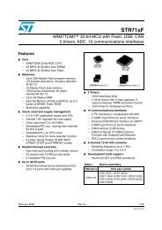
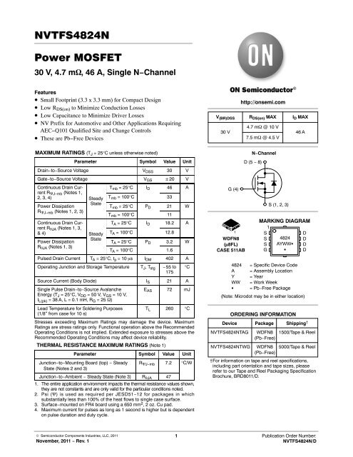
NVTFS4824N<strong>Power</strong> <strong>MOSFET</strong>30 V, 4.7 m, 46 A, Single N−ChannelFeatures• Small Footprint (3.3 x 3.3 mm) for Compact Design• Low R DS(on) to Minimize Conduction Losses• Low Capacitance to Minimize Driver Losses• NV Prefix for Automotive and Other Applications RequiringAEC−Q101 Qualified Site and Change Controls• These are Pb−Free DevicesMAXIMUM RATINGS (T J = 25°C unless otherwise noted)Parameter Symbol Value UnitDrain−to−Source Voltage V DSS 30 VGate−to−Source Voltage V GS 20 VContinuous Drain CurrentR J−mb (Notes 1,2, 3, 4) SteadyState<strong>Power</strong> DissipationR J−mb (Notes 1, 2, 3)Continuous Drain CurrentR JA (Notes 1, 3,& 4)<strong>Power</strong> DissipationR JA (Notes 1, 3)SteadyStateT mb = 25°C I D 46 AT mb = 100°C 33T mb = 25°C P D 21 WT mb = 100°C 11T A = 25°C I D 18.2 AT A = 100°C 12.8T A = 25°C P D 3.2 WT A = 100°C 1.6Pulsed Drain Current T A = 25°C, t p = 10 s I DM 402 AOperating Junction and Storage Temperature T J , T stg −55 to175Source Current (Body Diode) I S 21 ASingle Pulse Drain−to−Source AvalancheEnergy (T J = 25°C, V DD = 50 V, V GS = 10 V,I L(pk) = 38 A, L = 0.1 mH, R G = 25 )Lead Temperature for Soldering Purposes(1/8″ from case for 10 s)°CE AS 72 mJT L 260 °CStresses exceeding Maximum Ratings may damage the device. MaximumRatings are stress ratings only. Functional operation above the RecommendedOperating Conditions is not implied. Extended exposure to stresses above theRecommended Operating Conditions may affect device reliability.THERMAL RESISTANCE MAXIMUM RATINGS (Note 1)Parameter Symbol Value UnitJunction−to−Mounting Board (top) − SteadyState (Notes 2 and 3)R J−mb 7.2 °C/WJunction−to−Ambient − Steady State (Note 3) R JA 471. The entire application environment impacts the thermal resistance values shown,they are not constants and are only valid for the particular conditions noted.2. Psi () is used as required per JESD51−12 for packages in whichsubstantially less than 100% of the heat flows to single case surface.3. Surface−mounted on FR4 board using a 650 mm 2 , 2 oz. Cu pad.4. Maximum current for pulses as long as 1 second is higher but is dependenton pulse duration and duty cycle.http://onsemi.comV (BR)DSS R DS(on) MAX I D MAX30 VG (4)1WDFN8(8FL)CASE 511AB4.7 m @ 10 V7.5 m @ 4.5 VORDERING INFORMATI<strong>ON</strong>46 A(Note: Microdot may be in either location)Device Package Shipping †NVTFS4824NTAG4824 = Specific Device CodeA = Assembly LocationY = YearWW = Work Week = Pb−Free PackageNVTFS4824NTWGN−ChannelD (5 − 8)WDFN8(Pb−Free)WDFN8(Pb−Free)S (1, 2, 3)MARKING DIAGRAM1SDS 4824 DS AYWW DG D1500/Tape & Reel5000/Tape & Reel†For information on tape and reel specifications,including part orientation and tape sizes, pleaserefer to our Tape and Reel Packaging SpecificationBrochure, BRD8011/D.© <strong>Semiconductor</strong> Components Industries, LLC, 2011November, 2011 − Rev. 11 Publication Order Number:NVTFS4824N/D
NVTFS4824NELECTRICAL CHARACTERISTICS (T J = 25°C unless otherwise noted)Parameter Symbol Test Condition Min Typ Max UnitOFF CHARACTERISTICSDrain−to−Source Breakdown Voltage V (BR)DSS V GS = 0 V, I D = 250 A 30 VZero Gate Voltage Drain Current I DSS VGS = 0 V,V DS = 30 VT J = 25°C 1.0 AT J = 125°C 10Gate−to−Source Leakage Current I GSS V DS = 0 V, V GS = 20 V 100 nA<strong>ON</strong> CHARACTERISTICS (Note 5)Gate Threshold Voltage V GS(TH) V GS = V DS , I D = 250 A 1.5 2.5 VDrain−to−Source On Resistance R DS(on) V GS = 10 V, I D = 23 A 3.5 4.7 mV GS = 4.5 V, I D = 23 A 5.7 7.5Forward Transconductance g FS V DS = 1.5 V, I D = 20 A 56 SCHARGES AND CAPACITANCESInput Capacitance C iss 1740 pFOutput Capacitance C oss V GS = 0 V, f = 1.0 MHz, V DS = 12 V360Reverse Transfer Capacitance C rss 200Threshold Gate Charge Q G(TH) 1.6Total Gate Charge Q G(TOT)Gate−to−Source Charge Q GSV GS = 4.5 V, V DS = 15 V, I D = 23 A5.3Gate−to−Drain Charge Q GD 5.514 nCTotal Gate Charge Q G(TOT) V GS = 10 V, V DS = 15 V, I D = 23 A 29 nCTurn−On Delay Time t d(on)SWITCHING CHARACTERISTICS (Note 6)12 nsRise Time t r V GS = 4.5 V, V DS = 15 V,27Turn−Off Delay Time t d(off)I D = 23 A, R G = 3.0 20Fall Time t f 6DRAIN−SOURCE DIODE CHARACTERISTICSForward Diode Voltage V SD V GS = 0 V,I S = 23 AT J = 25°C 0.81 1.1 VT J = 125°C 0.69Charge Time t a V GS = 0 V,9.1Discharge Time t bdI S /dt = 100 A/s,I S = 23 A9.619 nsReverse Recovery Charge Q RR 8.8 nC5. Pulse Test: Pulse Width ≤ 300 s, Duty Cycle ≤ 2%.6. Switching characteristics are independent of operating junction temperatures.http://onsemi.com2
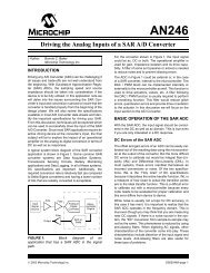
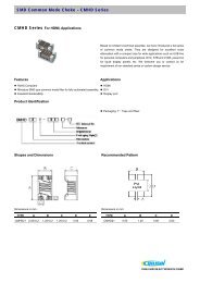
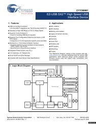
NVTFS4824NTYPICAL CHARACTERISTICSI D , DRAIN CURRENT (A)12510 V4.5 V1005 V754.0 V3.6 V50V GS = 3.2 V25T J = 25°C00 1 2 3 4 5V DS , DRAIN−TO−SOURCE VOLTAGE (V)Figure 1. On−Region CharacteristicsI D , DRAIN CURRENT (A)125V DS ≥ 10 V1007550T J = 100°C25T J = 25°CT0J = −55°C2 3 4 5 6V GS , GATE−TO−SOURCE VOLTAGE (V)Figure 2. Transfer CharacteristicsR DS(on) , DRAIN−TO−SOURCE RESISTANCE ()0.0200.0150.0100.005I D = 23 AT J = 25°C0.0000 2 4 6 8 10V GS , GATE−TO−SOURCE VOLTAGE (V)Figure 3. On−Resistance vs. Gate−to−SourceVoltageR DS(on) , DRAIN−TO−SOURCE RESISTANCE ()0.0080.0060.004T J = 25°CV GS = 4.5 VV GS = 10 V0.00210 20 30 40 50 60I D , DRAIN CURRENT (A)Figure 4. On−Resistance vs. Drain Current andGate Voltage1.810000R DS(on) , DRAIN−TO−SOURCERESISTANCE (NORMALIZED)1.61.41.21.00.8I D = 23 AV GS = 4.5 VI DSS , LEAKAGE (nA)1000100V GS = 0 VT J = 150°CT J = 125°C0.6−50 −25 0 25 50 75 100 125 150 175T J , JUNCTI<strong>ON</strong> TEMPERATURE (°C)Figure 5. On−Resistance Variation withTemperature105 10 15 20 25 30V DS , DRAIN−TO−SOURCE VOLTAGE (V)Figure 6. Drain−to−Source Leakage Currentvs. Voltagehttp://onsemi.com3
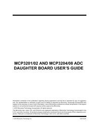
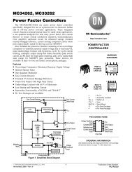
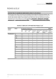
NVTFS4824NTYPICAL CHARACTERISTICSC, CAPACITANCE (pF)2500200015001000C iss500C2ossI D = 23 AC T rss J = 25°C000 10 20 30 0 10 20 30GATE−TO−SOURCE OR DRAIN−TO−SOURCE VOLTAGE (V)Q g , TOTAL GATE CHARGE (nC)Figure 7. Capacitance VariationV GS = 0 VT J = 25°CV GS , GATE−TO−SOURCE VOLTAGE (V)10864Q gsQ gdQ TFigure 8. Gate−to−Source Voltage vs. TotalCharge100060t, TIME (ns)10010V DD = 15 VI D = 23 AV GS = 4.5 VI S , SOURCE CURRENT (A)t d(off)20t rtt d(on)f040V GS = 0 VT J = 25°C11 10 100R G , GATE RESISTANCE ()Figure 9. Resistive Switching Time Variationvs. Gate Resistance0.40 0.50 0.60 0.70 0.80 0.90V SD , SOURCE−TO−DRAIN VOLTAGE (V)Figure 10. Diode Forward Voltage vs. CurrentI D , DRAIN CURRENT (A)10001001011 msV GS = 4.5 VSingle PulseT C = 25°C10 s100 s10 ms0.1R DS(on) LimitThermal LimitPackage Limit0.010.1 1 10 100V DS , DRAIN−TO−SOURCE VOLTAGE (V)Figure 11. Maximum Rated Forward BiasedSafe Operating AreadcE AS , SINGLE PULSE DRAIN−TO−SOURCE AVALANCHE ENERGY (mJ)755025I D = 38 A025 50 75 100 125 150 175T J , STARTING JUNCTI<strong>ON</strong> TEMPERATURE(°C)Figure 12. Maximum Avalanche Energy vs.Starting Junction Temperaturehttp://onsemi.com4
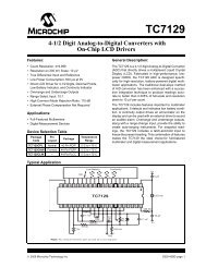
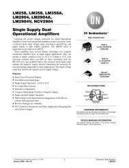
NVTFS4824NTYPICAL CHARACTERISTICS10Duty Cycle = 0.5RJ_mb−top R(t) (°C/W)10.10.20.10.050.020.01Single Pulse0.010.000001 0.00001 0.0001 0.001 0.01 0.1 1PULSE TIME (sec)Figure 13. Thermal Responsehttp://onsemi.com5
NVTFS4824NPACKAGE DIMENSI<strong>ON</strong>S0.10 C0.10 C8X0.10 C A B0.05 C4X L2X0.20 CD AB 2XD18 7 6 5E1 E1 2 3 4cTOP VIEWASIDE VIEW DETAIL Ae/214K0.20WDFN8 3.3x3.3, 0.65PCASE 511ABISSUE CC6XeDETAIL A4XA1CSEATINGPLANENOTES:1. DIMENSI<strong>ON</strong>ING AND TOLERANCING PER ASME Y14.5M, 1994.2. C<strong>ON</strong>TROLLING DIMENSI<strong>ON</strong>: MILLIMETERS.3. DIMENSI<strong>ON</strong> D1 AND E1 DO NOT INCLUDE MOLD FLASHPROTRUSI<strong>ON</strong>S OR GATE BURRS.PACKAGEOUTLINEMILLIMETERSINCHESDIM MIN NOM MAX MIN NOM MAXA 0.70 0.75 0.80 0.028 0.030 0.031A1 0.00 0.05 0.000 0.002b 0.23 0.30 0.40 0.009 0.012 0.016c 0.15 0.20 0.25 0.006 0.008 0.010D3.30 BSC0.130 BSCD1 2.95 3.05 3.15 0.116 0.120 0.124D2 1.98 2.11 2.24 0.078 0.083 0.088E3.30 BSC0.130 BSCE1 2.95 3.05 3.15 0.116 0.120 0.124E2 1.47 1.60 1.73 0.058 0.063 0.068E3 0.23 0.30 0.40 0.009 0.012 0.016e0.65 BSC 0.026 BSCG 0.30 0.41 0.51 0.012 0.016 0.020K 0.64 0.025 L 0.30 0.43 0.56 0.012 0.017 0.022L1 0.06 0.13 0.20 0.002 0.005 0.008M1.400° 1.501.6012° 0.0550° 0.0590.06312°SOLDERING FOOTPRINT*8X0.420.65PITCH4X0.66E2E3MG8 5D2BOTTOM VIEWL10.750.572.303.600.472.373.46DIMENSI<strong>ON</strong>: MILLIMETERS*For additional information on our Pb Free strategy and solderingdetails, please download the <strong>ON</strong> <strong>Semiconductor</strong> Soldering andMounting Techniques Reference Manual, SOLDERRM/D.<strong>ON</strong> <strong>Semiconductor</strong> and are registered trademarks of <strong>Semiconductor</strong> Components Industries, LLC (SCILLC). SCILLC reserves the right to make changes without further noticeto any products herein. SCILLC makes no warranty, representation or guarantee regarding the suitability of its products for any particular purpose, nor does SCILLC assume any liabilityarising out of the application or use of any product or circuit, and specifically disclaims any and all liability, including without limitation special, consequential or incidental damages.“Typical” parameters which may be provided in SCILLC data sheets and/or specifications can and do vary in different applications and actual performance may vary over time. Alloperating parameters, including “Typicals” must be validated for each customer application by customer’s technical experts. SCILLC does not convey any license under its patent rightsnor the rights of others. SCILLC products are not designed, intended, or authorized for use as components in systems intended for surgical implant into the body, or other applicationsintended to support or sustain life, or for any other application in which the failure of the SCILLC product could create a situation where personal injury or death may occur. ShouldBuyer purchase or use SCILLC products for any such unintended or unauthorized application, Buyer shall indemnify and hold SCILLC and its officers, employees, subsidiaries, affiliates,and distributors harmless against all claims, costs, damages, and expenses, and reasonable attorney fees arising out of, directly or indirectly, any claim of personal injury or deathassociated with such unintended or unauthorized use, even if such claim alleges that SCILLC was negligent regarding the design or manufacture of the part. SCILLC is an EqualOpportunity/Affirmative Action Employer. This literature is subject to all applicable copyright laws and is not for resale in any manner.PUBLICATI<strong>ON</strong> ORDERING INFORMATI<strong>ON</strong>LITERATURE FULFILLMENT:Literature Distribution Center for <strong>ON</strong> <strong>Semiconductor</strong>P.O. Box 5163, Denver, Colorado 80217 USAPhone: 303−675−2175 or 800−344−3860 Toll Free USA/CanadaFax: 303−675−2176 or 800−344−3867 Toll Free USA/CanadaEmail: orderlit@onsemi.comN. American Technical Support: 800−282−9855 Toll FreeUSA/CanadaEurope, Middle East and Africa Technical Support:Phone: 421 33 790 2910Japan Customer Focus CenterPhone: 81−3−5817−1050http://onsemi.com6<strong>ON</strong> <strong>Semiconductor</strong> Website: www.onsemi.comOrder Literature: http://www.onsemi.com/orderlitFor additional information, please contact your localSales RepresentativeNVTFS4824N/D