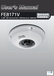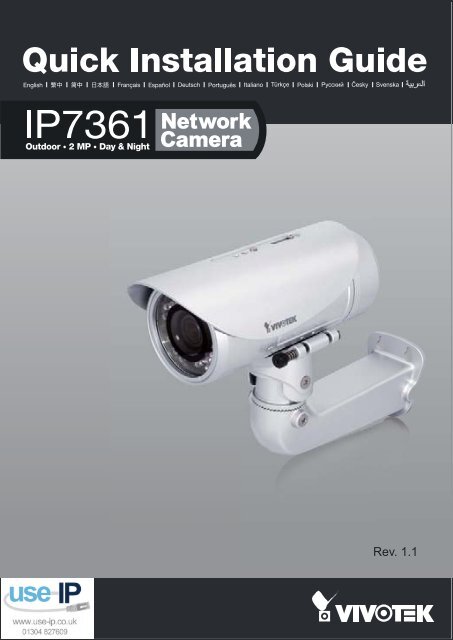
Vivotek IP7361 Installation Guide - Use-IP
Vivotek IP7361 Installation Guide - Use-IP
Vivotek IP7361 Installation Guide - Use-IP

You also want an ePaper? Increase the reach of your titles
YUMPU automatically turns print PDFs into web optimized ePapers that Google loves.
EnglishWarning Before <strong>Installation</strong>Power off the Network Camera assoon as smoke or unusual odors aredetected.Refer to your user's manual for theoperating temperature.Contact your distributor in theevent of occurrence.Do not place the Network Camera onunsteady surfaces.Do not touch the Network Cameraduring a lightning storm.Do not insert sharp or tiny objectsinto the Network Camera.Do not drop the Network Camera.EN-1
1Package Contents<strong><strong>IP</strong>7361</strong> with an RJ45 CableSun ShieldWall Mount BracketRJ45Waterproof Connector for RJ45Ethernet EnclosurePower AdapterAlignment Sticker / Silica GelWaterproof Connector (for backupuse)Software CDQuick <strong>Installation</strong> <strong>Guide</strong>Warranty CardEN-2
English2Physical DescriptionIR LEDLensLight SensorSD/SDHC Card SlotGeneral I/OTerminal BlockReset ButtonStatus LEDPower Cord SocketRJ45 CableEN-3
3Hardware <strong>Installation</strong>1. Attach the alignment sticker to the wall. Drill four holes into the wall. Then hammer the suppliedplastic anchors into the holes and secure the plate with supplied screws.2. Fix the ㄇ-bracket to the side of the Network Camera with two screws.3. Feed the RJ45 cable through the front opening of the wall mount bracket. (If you want to useexternal devices such as sensors and alarms, please refer to the assembling steps on the nextpage.)4. Open the lens cover.5. Push the spring mortise and hook the bracket onto the groove of the wall mount bracket.6. Secure the two screws on the other side of the wall mount bracket.7. Hang the wall mount bracket on the plate.8. Fix the wall mount bracket with the supplied screw.9. Adjust the angle of the wall mount bracket to aim at the shooting area.124365798EN-4
EnglishWaterproof ConnectorComponents of the Waterproof ConnectorScrew Nut (A)Seal (B)Seals (C)Housing (D)Sealing Nut (E)Pin Definition1 2 3 4 5 6 7 843211 Power +12V2 Digital Output3 Digital Input4 Ground5 AC 24V6 AC 24V7 RS485 +8 RS485 -1 External MIC In2 Ground3 Audio Out4 GroundAssembling Steps1. Disassemble the components of the waterproof connector into part (A) ~ (E) as shown above.2. Open the back cover of the Network Camera.3. Remove the rubber stopper from the bottom of the Network Camera and secure the screw nut (A)tightly.4. If you need extra power for external devices, please feed the power cable through the wall mountbracket and the waterproof connector (E --> D --> B --> A) as the illustration shown below. Thenconnect the power cord to the socket. Note: There are 7 holes on the seal (B), and the widest holewith a crack on the side is specific for power cord.5. If you have external devices such as sensors and alarms, feed the cables through the wall mountbracket and the waterproof connector (E --> D --> B --> A) as the illustration shown below. Thenrefer to the pin definition to connect them to the general I/O terminal block. Note: The recommendedcable gauge is 2.0 ~ 2.8 mm.6. Push the seal (B) into the housing (D).7. Insert the seals (C) into the empty holes on the seal (B) to avoid moisture.8. Secure the sealing nut (E) tightly.573(A)(B)(B)6(D)(C)(D)(E)448(E)EN-5
4Cabling AssemblyRJ45 Cable ConnectorRJ45 Cable Dimension (unit: mm)Components of the WaterproofConnectorSealing Nut (A)Seal (B)Screw Nut (C)Housing (D)Gasket (E)Assembling Steps1 Prepare an Ethernet cable2 Insert the housing into the3and strip part of the sheath.screw nut.Insert the seal into the housing.(C)(D)(B)Recommended cable gauge: 24AWG(0.51 mm)4 Insert the stripped Ethernet5 Clamp the cable with6cable through the sealingan RJ45 plug.nut and the housing.(A)Push the RJ45 plug into thehousing, then secure thesealing nut tightly.7 Attach the gasket to the front 8of the housing.(E)Connect the Ethernet cable to the RJ45 cable and secure theconnectors tightly.EN-6
6Assigning an <strong>IP</strong> Address1. Install "<strong>Installation</strong> Wizard 2" from the Software Utility directory on the software CD.2. The program will conduct an analysis of your network environment. After your networkis analyzed, please click on the "Next" button to continue the program.IW2<strong>Installation</strong>Wizard 23. The program will search for VIVOTEK Video Receivers, Video Servers, and NetworkCameras on the same LAN.4. After searching, the main installer window will pop up. Click on the MAC that matchesthe one labeled on the side of the camera or S/N number on the label of carton toconnect the Internet Explorer to the Network Camera.10002D17151CD00-02-D1-07-25-8A 192.168.5.151 <strong><strong>IP</strong>7361</strong>2 Model No.: <strong><strong>IP</strong>7361</strong>P/N:100043690G0002D17151CDEAN: 4712123671550Q 'ty: 1 PCSS/N:0002D17151CDF/W Ver.: 0100dCARTO N O F NO . / 01MADE IN TAIWANEN-8
English7Ready to <strong>Use</strong>1. Access the Network Camera from the LAN.2. Retrieve live video through a web browser or recording software.For further setup, please refer to the user's manual on the software CD.3. Unscrew the zoom controller to adjust thezoom factor. Upon completion, tighten thezoom controller.4. Unscrew the focus controller to adjust thefocus range. Upon completion, tighten thefocus controller.N4T∞W3EN-9