Tapered Internal Dental Implant Catalog - BioHorizons
Tapered Internal Dental Implant Catalog - BioHorizons
Tapered Internal Dental Implant Catalog - BioHorizons
- No tags were found...

Create successful ePaper yourself
Turn your PDF publications into a flip-book with our unique Google optimized e-Paper software.
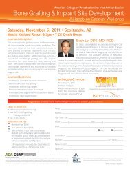
Laser-Lok TechnologyLaser-Lok overviewLaser-Lok microchannels is a proprietary dentalimplant surface treatment developed from over 20years of research initiated to create the optimal implantsurface. Through this research, the unique Laser-Loksurface has been shown to elicit a biologic responsethat includes the inhibition of epithelial downgrowthand the attachment of connective tissue (unlikeSharpey fibers). 1,2 This physical attachment producesa biologic seal around the implant that protectsand maintains crestal bone health. The Laser-Lokphenomenon has been shown in post-market studiesto be more effective than other implant designs inreducing bone loss. 3,4,5,6SEM image at 30X showing the Laser-Lok zoneon a <strong>BioHorizons</strong> implant.The uniformity of the Laser-Lok microstructureand nanostructure is evident using extrememagnification.Unique surface characteristicsLaser-Lok microchannels is a series of cell-sized circumferential channels that are precisely created using laser ablation technology.This technology produces extremely consistent microchannels that are optimally sized to attach and organize both osteoblasts andfibroblasts. 7,8 The Laser-Lok microstructure also includes a repeating nanostructure that maximizes surface area and enables cellpseudopodia and collagen microfibrils to interdigitate with the Laser-Lok surface.soft tissueLaser-LokimplantLaser-LokimplantHuman histology shows the apical extent of thejunctional epithelium below which there is asupracrestal connective tissue attachment to theLaser-Lok surface. 1bonePolarized lights show the connective tissue isfunctionally oriented. 1Colorized SEM of a dental implant harvested at6 months post-op shows the connective tissue isphysically attached and interdigitated with theLaser-Lok surface.Different than other surface treatmentsVirtually all dental implant surfaces on the market are grit-blasted and/or acid-etched. These manufacturing methods createrandom surfaces that vary from point to point on the implant and alter cell reaction depending on where each cell comes in contactwith the surface. 9 While random surfaces have shown higher osseointegration than machined surfaces, 10 only the Laser-Lok surfacehas been shown using light microscopy, polarized light microscopy and scanning electron microscopy to also be effective for softtissue attachment. 1,11shop online at www.biohorizons.com1
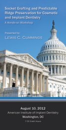
The clinical advantageThe Laser-Lok surface has been shown in several studiesto offer a clinical advantage over other implant designs.In a prospective, controlled multi-center study, Laser-Lok implants, when placed alongside identical implantswith a traditional surface, were shown at 37 monthspost-op to reduce bone loss by 70% (or 1.35mm). 3 In aretrospective, private practice study, Laser-Lok implantsplaced in a variety of site conditions and followed up to 3years minimized bone loss to 0.46mm. 4 In a prospective,University-based overdenture study, Laser-Lok implantsreduced bone loss by 63% versus NobelReplace Select. 5Change in Bone Level (mm)Crestal Bone LossLaser-LokControl0.00-0.500.59mm-1.00Laser-Lok advantage-1.501.94mm-2.00-2.501 5 9 13 17 21 25 29 33 37Months Post-OpIn a 3-year multicenter perspective study, the Laser-Lok surface showed superior bone maintenanceover identical implants without the Laser-Lok surface. 3Latest discoveriesThe establishment of a physical, connective tissueattachment (unlike Sharpey fibers) to the Laser-Loksurface has generated an entirely new area of research anddevelopment: Laser-Lok applied to abutments. This couldprovide an opportunity to use Laser-Lok abutments tocreate a biologic seal and Laser-Lok implants to establishsuperior osseointegration 8 – a solution that offers the bestof both worlds. Alternatively, Laser-Lok abutments couldsupport peri-implant health around implants withoutLaser-Lok. In a recent study, Laser-Lok abutments andstandard abutments were randomly placed on implantswith a grit-blasted surface to evaluate the differences. Inthis proof-of-principle study, a small band of Laser-Lokmicrochannels was shown to inhibit epithelial downgrowthand establish a connective tissue attachment (unlikeSharpey fibers) similar to Laser-Lok implants. 11 This time,however, the attachment was established above the dentalimplant-abutment connection and even on implants witha machined collar. 11 The resulting crestal bone levels werehigher than what was seen with standard abutments andprovides some insight into the role soft tissue stability mayplay in maintaining crestal bone health.EpithelialdowngrowthBonelossStandardabutmentat 3 months200µmLaser-Lokabutmentat 3 monthsConnectivetissueNewboneComparative histologies show the biologic differences between standard abutments and Laser-Lokabutments including changes in epithelial downgrowth, connective tissue and crestal bone health. 11Exposedimplant collarStandardabutmentat 3 monthsLaser-Lokabutmentat 3 monthsLaser-LokmicrochannelstissueflapComparative SEM images show the variation in tissue attachment strength on standard and Laser-Lokabutments when a tissue flap is incised vertically and manually lifted using forceps. 11Laser-Lok Technologyis available on Laser-Lok 3.0,<strong>Tapered</strong> <strong>Internal</strong>, Single-stage &<strong>Internal</strong> implants2shop online at www.biohorizons.com• NobelReplace is a trademark of Nobel Biocare.
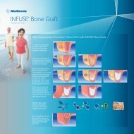
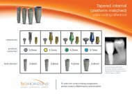
TAPERED INTERNAL IMPLANTStapered internal<strong>Tapered</strong> <strong>Internal</strong> dental implants provide excellent primary stability, maximum bone maintenance and soft tissueattachment for optimal esthetics. The <strong>Tapered</strong> <strong>Internal</strong> implant achieves these benefits from its anatomicallytapered dental implant body, aggressive buttress threads and advanced Laser-Lok surface technology. The deep1.5mm internal hex connection with a lead-in tapered bevel create a rigid connection and a stable biologic seal.• Excellent primary stability from anatomically tapered body• Compressive bone loading from proprietary buttress threads• Stable soft tissue seal and flexible implant placement from Laser-Lok microchannelsComprehensive line of internally hexed prosthetics.Laser-LokSurfaceCollagenfibersBoneLaser-Lok shown to have functionallyorientedconnective tissue attachment. 1Buttress threads have a wide, flatleading edge for increased functionalsurface area, improved axial loaddistribution and primary stability.shop online at www.biohorizons.com3
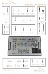
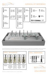
SURGICAL INSTRUMENTS<strong>Tapered</strong> <strong>Internal</strong> Surgical KitTSK2021<strong>Tapered</strong> <strong>Internal</strong> Surgical Kit (complete)Reduced height tray with increased ventilation for fasterdrying and convenient drill measurement guide. Includes allinstruments shown on pages 5 & 6.TSK2011<strong>Tapered</strong> <strong>Internal</strong> Tray & Lid (without instruments)Individual Kit ComponentsTSD20202.0mm Starter Drill (matte finish)TSD20252.5mm Depth Drill (matte finish)122-100Drill Extender(adds 16mm tolength of drill)144-100Straight Parallel Pins (2 per kit)144-20020° Angled Parallel Pins (2 per kit)TSD2032TSD2037TSD2041TSD2047TSD20543.2mm Width Increasing Drill (matte finish)3.7mm Width Increasing Drill (matte finish)4.1mm Width Increasing Drill (matte finish)4.7mm Width Increasing Drill (matte finish)5.4mm Width Increasing Drill (matte finish)TSC20383.8mm Crestal Bone DrillTST20383.8mm Bone TapTSC20464.6mm Crestal Bone DrillTST20464.6mm Bone TapTSC20585.8mm Crestal Bone DrillTST20585.8mm Bone Tapshop online at www.biohorizons.com5
SURGICAL INSTRUMENTSIndividual Kit ComponentsTDG20383.8mm Depth GaugePHAAbutment-level Driver, Handpiece*TDG20464.6mm Depth GaugePRAAbutment-level Driver, Ratchet*TDG20585.8mm Depth GaugeSYGIDRSBIDR3.5/4.5mm <strong>Implant</strong>-level Driver, Ratchet*5.7mm <strong>Implant</strong>-level Driver, Ratchet*SYGIDHSBIDH3.5/4.5mm <strong>Implant</strong>-level Driver, Handpiece*5.7mm <strong>Implant</strong>-level Driver, Handpiece*130-000 144-300Ratchet<strong>Implant</strong> Spacer / Depth Probe300-400Hand Wrench*135-351.050” (1.25mm) Hex DriverIn January 2011, a running changewas made to improve abutmentscrew retention and handling.300-2064mm Square Drive Extender*Replaced 300-205 starting in June 2010.Includes PEEK C-ring for durable retentionin Ratchet. Cannot be used with bone taps.*instrument o-rings & c-rings wear out over time. If an instrument is no longer held securely by its associated driver, order a replacement ring through Customer Care.shop online at www.biohorizons.com6
ANCILLARY INSTRUMENTS2.5mm <strong>Tapered</strong> Depth Drills with stopsTSD202507TSD202509TSD202510TSD202512TSD2025152.5mm <strong>Tapered</strong> Depth Drill, 7.5mm Stop2.5mm <strong>Tapered</strong> Depth Drill, 9mm Stop2.5mm <strong>Tapered</strong> Depth Drill, 10.5mm Stop2.5mm <strong>Tapered</strong> Depth Drill, 12mm Stop2.5mm <strong>Tapered</strong> Depth Drill, 15mm StopStops are set to same length as each implant for crestal placement.Laser-etched line set 1mm shorter for supracrestal placement.Extended Shank DrillsTSD4020TSD4025TSD4032TSD4037TSD4041TSD4047TSD40542.0mm Ext. Shank Starter Drill2.5mm Ext. Shank Depth Drill3.2mm Ext. Shank Width Increasing Drill3.7mm Ext. Shank Width Increasing Drill4.1mm Ext. Shank Width Increasing Drill4.7mm Ext. Shank Width Increasing Drill5.4mm Ext. Shank Width Increasing DrillExtended Shank Drills are 8mm longer than our standard drills.Burs122-110 2.0mm Lindemann Bone CutterSide-cutting drill used to correct eccentric osteotomy preparations.122-106 #6 Round BurHandpiece Hex Drivers134-350134-450.050” (1.25mm) Handpiece Hex Driver.050” (1.25mm) Handpiece Hex Driver, Long6.5mm11.5mmFor installation and removal of Cover Screws, Healing Abutments andAbutment Screws. The Handpiece Hex Drivers are used with latch-typecontra-angle handpieces. The Handpiece Hex Driver, Long (134-450) is5mm longer than the standard version (134-350).shop online at www.biohorizons.com7
ANCILLARY INSTRUMENTSDrivers150-000Surgical DriverUse to drive implants into the osteotomy, particularly in the anterior region.The driver holds the Abutment-level Driver, Ratchet which interfaces withthe 3inOne Abutment. Also interfaces with the .050” (1.25mm) Hex Driversas well as Bone Taps and the <strong>Implant</strong>-level Drivers, Ratchet.PADHHAbutment-level Driver,Hex-chuck Handpiece*Use with compatible W&H HexagonChucking System Handpieces to preventdeformation of the ISO shank latchconnection in high-torque applications.Adjustable Torque WrenchesEL-C12374Elos Adjustable Torque WrenchLightweight titanium design is easy to use as an adjustabletorque wrench or a ratchet. Quickly disassembles forcleaning. No calibration required.ATWITL Precise Adjustable Torque WrenchPlace both implants and abutments with 9 distinct torque settings(15, 20, 25, 30, 35, 40, 45, 50 and 60 Ncm). A simple twist of thehandle locks in precision-engineered torque values and guaranteesaccuracy and repeatability.Tissue PunchesPYTPPGTPPBTP3.5mm Tissue Punch4.5mm Tissue Punch5.7mm Tissue PunchUse in a latch-type handpiece to remove the soft tissue from the crest of the ridge prior toosteotomy preparation in a flapless surgical procedure. Available in three platform diameters.Bone Profiling BursPYBPPGBPPBBP3.5mm Bone Profiling Bur & Guide4.5mm Bone Profiling Bur & Guide5.7mm Bone Profiling Bur & GuideUse at implant uncovery to contour crestal bone for abutments when the implant is subcrestal.The Profiling bur’s internal geometry matches the geometry of the included Profiler Guide. TheGuide is screwed into the implant and then aligns the Profiling bur’s for precise removal of tissuesurrounding the platform. Available in three sizes.*instrument o-rings & c-rings wear out over time. If an instrument is no longer held securely by its associated driver, order a replacement ring through Customer Care.shop online at www.biohorizons.com8
W&H MOTORS AND ACCESSORIES<strong>BioHorizons</strong> proudly distributes W&H implant motors, handpieces and accessories.Additional W&H products and re-order items are available. For more information, contactyour <strong>BioHorizons</strong> representative or visit the online catalog (www.biohorizons.com).W&H Motor KitsMotor Kits include: console, motor with 1.8m attached cable, standard (<strong>Implant</strong>MED) or premium (ElcoMED) foot pedal, (3) completedisposable irrigation tubes, USB documentation (ElcoMED), handpiece, bur testing gauge, spray cap and service oil (ships separately).WH-310LElcoMED SA-310 Professional Kit with LEDIncludes LED handpiece (WH-10207530).WH-310ElcoMED SA-310 Professional KitIncludes handpiece (WH-10207510).WH-915L<strong>Implant</strong>MED 915 Starter Kit with LEDIncludes mono block LED handpiece (WH-10207560).WH-915<strong>Implant</strong>MED SI-915 Starter KitIncludes mono block handpiece (WH-10207550).W&H MotorsWH-00900103WH-15933100<strong>Implant</strong>MED SI-915 (S-NU Foot Pedal) 1.8m Cable, Blue ConsoleElcoMED SA-310 (with Documentation) 1.8m CableW&H ElcoMED SA-310 and <strong>Implant</strong>MED SI-915 Re-Order itemsWH-04363600WH-06338400WH-04757100WH-10940011WH-02038200WH-04035100WH-04013900WH-06338500WH-04035200WH-04014000WH-00929300WH-04032600WH-04019000Disposable Irrigation Tubing, 2.2m (<strong>Implant</strong>med and ElcoMED SA-310) (box of 6)Irrigation Spike w/ Roller ClampIrrigation Spray Clip for External and <strong>Internal</strong> Irrigation (set of 3)MD-400 Service-Oil F1Oil Spray Cap for MD-400 Service-Oil F1Pump Tube Complete (ElcoMED SA-200(C)Pump Tube Complete (<strong>Implant</strong>MED and ElcoMED SA-310)Spare Irrigation Tube for SpikeSpare Pump Tubes (ElcoMED SA-200(C) (set of 3)Spare Pump Tubes (<strong>Implant</strong>MED and ElcoMED SA-310) (set of 3)Spray Tubes (box of 10)Sterilization Motor ProtectorTube Clamps (<strong>Implant</strong>MED) (set of 5)shop online at www.biohorizons.com9
W&H MOTORS AND ACCESSORIESSurgical HandpiecesWH-10207530WS-75 E/KM LED G Surgical 20:1 Contra-AngleLED, 20:1, hexagon chucking system, press-button chuck system, forsurgical burs and cutters with a 2.35mm contra-angle shank, internaland external cooling system. Dismantle for easy cleaning.WH-10207510WS-75 E/KM Surgical 20:1 Contra-Angle20:1, hexagon chucking system, press-button chuck system, forsurgical burs and cutters with a 2.35mm contra-angle shank, internaland external cooling system. Dismantle for easy cleaning.WH-10207560WI-75 E/KM LED G Surgical 20:1 Contra-Angle, Mono BlockLED, 20:1, hexagon chucking system, press-button chuck system, for surgicalburs and cutters with a 2.35mm contra-angle shank, internal and externalcooling system.WH-10207550WI-75 E/KM Surgical 20:1 Contra-Angle, Mono Block20:1, hexagon chucking system, press-button chuck system, forsurgical burs and cutters with a 2.35mm contra-angle shank, internaland external cooling system.WH-10209201WS-92 E/3 Surgical 1:2.7 Contra-Angle1:2.7, press-button chuck system with triple spray, for surgical burs andcutters with a 1.6mm friction grip shank. Dismantle for easy cleaning.WH-10101200WH-00001100S-12 Surgical 1:2 Angled1:2, angled, extra slim tip for increased vision, lever chuck system, forsurgical burs and cutters 2.35mm >70mm extra long shaft. Dismantlefor easy cleaning.S-11 Surgical 1:1 Straight1:1, straight, lever chuck system, for surgical burs and cutters2.35mm >45mm shaft. Dismantle for easy cleaning.Prosthodontic ScrewdriverWH-16934000IA-400 Prosthodontic ScrewdriverCordless handpiece with precise torque control from8-40 Ncm, 80:1 contra-angle handpiece with hexagonchucking system, charging station, rechargeable Li-ionbattery, and power cable.Bur Testing GaugeWH-02139800Bur Testing GaugeUse to verify the condition of latch-type burs. Burs in proper conditionwill fit into larger diameter hole, but will not fit into the smaller hole(marked red). Burs that fail either of these tests are unfit for use, andmay cause damage to the handpiece.10shop online at www.biohorizons.com
HEALING ABUTMENTS & COVER CAPSHealing AbutmentsAbutment height(1, 3 or 5mm)Hand-tighten with the .050” (1.25mm) Hex Driver. Titanium Alloy.Laser marked for easy intraoral identification; for example:GR3 = Green (4.5mm) platform / Regular Emergence / 3mm HighRegular Emergence Prosthetic platform 1mm high 3mm high 5mm highPlatformdiameter3.5mm4.5mm5.7mmAbutmentdiameter4.5mm5.5mm6.6mm3.5mm Regular Healing Abutment4.5mm Regular Healing Abutment5.7mm Regular Healing AbutmentPYRHA3PGRHA3PBRHA3PYRHA5PGRHA5PBRHA5Narrow Emergence3.5mm4.5mm5.7mm3.8mm4.7mm5.9mm3.5mm Narrow Healing Abutment4.5mm Narrow Healing Abutment5.7mm Narrow Healing AbutmentPYNHA1PGNHA1PBNHA1PYNHA3PGNHA3PBNHA3PYNHA5PGNHA5PBNHA5Wide Emergence3.5mm4.5mm5.8mm6.8mm3.5mm Wide Healing Abutment4.5mm Wide Healing AbutmentPYWHA3PGWHA3PYWHA5PGWHA5Surgical Cover CapPYCCPGCCPBCC3.5mm Cover Cap4.5mm Cover Cap5.7mm Cover CapUse during submerged surgical healing. Hand-tighten with the .050” (1.25mm) Hex Driver.Titanium Alloy. Included with implant but can also be ordered separately.shop online at www.biohorizons.com11
SIMPLE SOLUTIONS ABUTMENTS WITH LASER-LOK TECHNOLOGYWith the success of <strong>BioHorizons</strong> Laser-Lok technology on implants, <strong>BioHorizons</strong> breaks new ground by applying this innovative technology toabutments. Simple Solutions abutments with Laser-Lok are designed to be seated at the time of implant placement or uncovery and remainin place through final restoration 12,13 . This establishes and maintains the connective tissue attachment.Laser-Lok has been shown to:• Inhibit epithelial downgrowth 1,11• Attract a physical connective tissue attachment 1,11(unlike Sharpey fiber attachment)• Preserve the coronal level of bone 1,11Laser-Lok Abutment PacksProsthetic platform /Abutment height0.8mm collar 1.8mm collar 2.8mm collar3.5mm Abutment, 4.0mmPY4008LPY4018LPY4028L3.5mm Abutment, 5.5mmPY5508LPY5518LPY5528L4.5mm Abutment, 4.0mmPG4008LPG4018LPG4028L4.5mm Abutment, 5.5mmPG5508LPG5518LPG5528L5.7mm Abutment, 4.0mmPB4008LPB4018LPB4028L5.7mm Abutment, 5.5mmPB5508LPB5518LPB5528LAbutment height(4.0 or 5.5mm)Collar height(0.8, 1.8 or 2.8mm)Simple Solutions crowns finish on the restorative shoulder of the abutment. There are three optionsfor transmucosal collar height: 0.8mm / 1.8mm / 2.8mm. Select the collar height that positions therestorative shoulder as close as possible to the desired position of the crown margin while allowingfor the Laser-Lok zone to be 1-2mm subgingival. Packaged with Abutment Screw (PXAS) andHealing Cap. Titanium Alloy. Final torque: 30Ncm.Restorative PacksSYRP40SYRP55SGRP40SGRP55SBRP40SBRP553.5mm Restorative Pack, 4.0mm Height3.5mm Restorative Pack, 5.5mm Height4.5mm Restorative Pack, 4.0mm Height4.5mm Restorative Pack, 5.5mm Height5.7mm Restorative Pack, 4.0mm Height5.7mm Restorative Pack, 5.5mm HeightEach restorative pack contains impression cap, replica and two waxing sleeves.12shop online at www.biohorizons.com
SURGICAL PROTOCOLSTwo-stage ProtocolIn a two-stage surgery, the implant is placed below the soft tissueand protected from occlusal function and other forces duringosseointegration. A low-profile Cover Cap is placed on the implant toprotect it from the ingress of soft tissue.<strong>Implant</strong> with Cover Cap ina two-stage protocol.Following osseointegration, a second procedure exposes the implantand a transmucosal Healing Abutment is placed to allow for softtissue healing and development of a sulcus. Prosthetic restorationbegins after soft tissue healing.Single-stage ProtocolSingle-stage surgery may be accomplished by placing a healingabutment at the time of implant surgery. This eliminates the needfor a second procedure. Although the implant is not in occlusalfunction, some forces can be transmitted to it through the exposedtransmucosal element.<strong>Implant</strong> with removable HealingAbutment in a single-stage protocol.Prosthetic restoration begins following osseointegration of theimplant and soft tissue healing.Non-functional Immediate RestorationSingle-stage surgery with non-functional immediate provisionalizationprovides the patient a non-functioning provisional prosthesis earlyin the treatment plan. An abutment is placed on the implant at orshortly after surgery, and a provisional restoration is secured usingtemporary cement. The provisional can help shape the soft tissueprofile during healing.<strong>Implant</strong> restored with a nonfunctionalprovisional prosthesis.Immediate Function RestorationSingle-stage surgery with immediate function is possible in goodquality bone where multiple implants exhibiting excellent initialstability can be splinted together. Splinting implants togethercan offer a significant biomechanical advantage over individual,unsplinted prostheses.<strong>Implant</strong>s with a splinted prosthesisin immediate function.14shop online at www.biohorizons.com
IMPLANT SPACINGDuring implant placement, clinicians must apply their best judgment as to the appropriate spacing forindividual patient conditions.The osteotomy centerpoint requiredto maintain a 1.5mm implant-to-toothspacing (generally accepted) is½ [implant body diameter] + 1.5mm.The osteotomy center-to-center measurement requiredto maintain a 3.0mm edge-to-edge spacing (generallyaccepted) between <strong>Tapered</strong> <strong>Internal</strong> implants is½ [sum of 2 implant body diameters] + 3.0mm.1.5mm1.5mm3.0mm3.8mmOsteotomy center 3.8mmfrom adjacent tooth(4.6mm implant pictured)8.2mmMeasurement is dependent on thetwo implant body diameters.(4.6 & 5.8mm implants pictured)bodydiameterosteotomy centerfrom adjacent toothbodydiameter3.8mm4.6mm5.8mm3.8mm3.4mm3.8mm6.8mm4.6mm3.8mm4.6mm7.2mm7.6mm5.8mm4.4mm5.8mm7.8mm8.2mm8.8mm<strong>Implant</strong> center to center<strong>Implant</strong> Spacer / Depth ProbePurpose: Multi-function instrument for intraoral measurements.• Five centimeter graduated ruler on shaft~4.25mm16mm14mm12mm10mm15mm13mm11mm9mm7mmThe rectangular end ofUseful for markingThe rectangular end against anProbe tip measures osteotomythe tool provides intraoralcenter-to-center implantexisting crown places the osteotomydepth. Note: these markings aremeasurements.spacing on the ridge.~4.25mm from the contact.different than the tapered drill markingsshop online at www.biohorizons.com15
IMPLANT PLACEMENT LEVEL & SURGICAL KIT LAYOUTPlacement in Uneven RidgesWhen placing the <strong>Tapered</strong> <strong>Internal</strong> implant in anuneven ridge, prepare the osteotomy and place theimplant so that the bone/soft-tissue junction is withinthe Laser-Lok transition zone. If the discrepancy ismore than the Laser-Lok transition zone, leveling theridge can be considered.Surgical Kit LayoutThe <strong>Tapered</strong> <strong>Internal</strong> Surgical Kit uses an intuitivelayout to guide the surgeon through the instrumentsequence. The sequence begins in the upper left handcorner and works left-to-right and then down. Colorcodedlines, instruments and grommets are matchedwith each implant and further aid in instrumentselection and identification.Prior to use, clean and sterilize the surgical tray andinstruments per appropriate Instructions for Useand study the Surgical Kit layout, color-coding andiconography. Surgical assistants should also bethoroughly familiar with all instruments and their uses.Depth DrillSequenceWidth IncreasingDrill SequenceDepthGaugesCrestalBone DrillsBoneTapsAbutment-level and/or<strong>Implant</strong>-level Driversshop online at www.biohorizons.com16
DRILL OVERVIEWAll surgical drills included with this system are externally irrigated and designed to be used at drill speeds of 850-2500 rpm 14with steady sterile irrigation. Reduced drill speed may be indicated in softer bone or as drill diameter increases.15.0mm12.0mm10.5mm9.0mm7.5mm<strong>Implant</strong>lengthNote: The depth marks are consistent throughout theStarter Drills, Depth Drills and Width Increasing DrillsImportant Considerations• Peri-operative oral rinses with a 0.12% Chlorhexidine Digluconate solution have been shown to significantly lower theincidence of post-implantation infectious complications. 15 A pre-operative 30-second rinse is recommended, followed bytwice daily rinses for two weeks following surgery.• Drilling must be done under a constant stream of sterile irrigation. A pumping motion should be employed to preventover-heating the bone. Surgical drills and taps should be replaced when they are worn, dull, corroded or in any waycompromised. <strong>BioHorizons</strong> recommends replacing drills after 12 to 20 osteotomies. 16 A Drill-usage Tracking Chart isavailable at biohorizons.com to record this important information.• There is a risk of injury to the mandibular nerve associated with surgical drilling in posterior mandibular regions. To minimizethe risk of nerve injury, it is imperative that the clinician understands the drill depth markings as they relate to the implantlength to produce the desired vertical placement of the implant.shop online at www.biohorizons.com17
OSTEOTOMY INITIALIZATION2.0mm Starter DrillPurpose: Initiate osteotomy.2.5mm Depth DrillPurpose: Set osteotomy depth.• Chisel-tip design eliminates“skating” on osseous crest• Prepares site for Paralleling Pins• Matte finish for increased visibilityunder operatory lights• Efficient cutting drill design collectsbone for autografting• Matte finish for increased visibilityunder operatory lightsThe 2.0mm and 2.5mm depth drills aredesigned to increase and/or set the depthof the osteotomy.2.5mm Depth Drills with StopsPurpose: Set osteotomy depth when access or visibility is poor.• Fixed circular ring acts as a definitive drill stop• One drill length for each implant length• 1mm laser-etched line guides supracrestal implant placement• <strong>BioHorizons</strong> Surgical Kit includes spare slots for Depth Drills with Stops or Extended Shank Drills18shop online at www.biohorizons.com
OSTEOTOMY MODIFICATIONParalleling PinsPurpose: Evaluate osteotomy position and angle.• Provided straight or with a 20° angle• Use after 2.0mm Starter Drill and 2.5mm Depth Drill• 9mm shank for radiographic evaluation of proximity to adjacent anatomy• Hub diameter is 4.0mm3.2 - 5.4mm Width Increasing DrillsPurpose: Incrementally widen the osteotomy to reduce heat generation.• Depth-marked for reference• Efficient cutting drill design collects bone for autografting• The drill tip has limited end cutting. However, the osteotomydepth can be increased with these drills as needed• Matte finish for increased visibility under operatory lightsDepth GaugesPurpose: Verify osteotomy depth.• Depth marks for reference• Use following the final Width Increasing Drill for each implant• Place the depth gauge into the osteotomy site,adjust osteotomy depth as necessary• Can also be used after 2mm drill by inverting15mm implant12mm implant10.5mm implant9mm implant7.5mm implantWidthIncreasingDrillDepth Gauge12mm <strong>Implant</strong>with Laser-Lokshop online at www.biohorizons.com19
FINAL BONE PREPARATION & DRIVERSCrestal Bone DrillsPurpose: Remove cortical bone at ridge crest for pressure-free seating of the implant collar.• Use when dense cortical bone is present at crest• Rounded non-end cutting hub centers drill in osteotomy• Use following the final Width Increasing Drill for each implantFully seat drill.<strong>Implant</strong> level withosseous crest.Bone TapsPurpose: Prepare dense cortical bone for implant threads.• Site specific• 30 rpm or less 17• Final instrument prior to implant placement• Can be driven with a handpiece, Ratchet or Hand WrenchPlace into the osteotomy, apply firm apical pressure and rotate slowly ina clockwise direction. When the threads engage, allow the tap to feedwithout excessive pressure. To remove, rotate the Bone Tap in a counterclockwisedirection, allowing it to back out of the osteotomy. Do not pullon the Bone Tap to remove it from the site.Abutment-Level DriversPurpose: Engage the pre-mounted 3inOne Abutment todrive into the osteotomy.<strong>Implant</strong>-level DriversPurpose: Engage the implant’s internal hex to drivemount-free implants into the osteotomy.• Drivers interface with the internal squareof the 3inOne Abutment• PEEK plastic snap ring secures3inOne Abutment• 30 rpm or less 17• May also be used followingremoval of the 3inOne Abutment• Offers a narrower path of insertionthan placing with a mount• 30 rpm or less 1720shop online at www.biohorizons.com
IMPLANT TRANSFER3inOne Mount TransferMount-free TransferCover CapSurgical mount<strong>Implant</strong><strong>Implant</strong>Cover CapThe Cover Cap for a two-stage surgicalprotocol is mounted on a plastic base andpackaged in the vial underneath the implant.The Cover Cap for a two-stage surgicalprotocol is mounted in the vial cap.driversquarePEEKsnap ringdriverhexPEEKsnap ringEngage the 3inOne Abutmentwith the PEEK snap ring of theAbutment-level driver. Thedriver square has no retentivefeature and does not needto be engaged. The driversquare will automaticallyengage in the osteotomy whenthe driver is slowly rotatedunder apical pressure.Engage the implant with thePEEK snap ring of the <strong>Implant</strong>levelDriver. The hex of the driverhas no retentive feature anddoes not need to be engaged.The driver hex will automaticallyengage in the osteotomy whenthe driver is slowly rotatedunder apical pressure.Excess pressure can deform the implantbasket and should be avoided.shop online at www.biohorizons.com21
PLACEMENT & ORIENTATION<strong>Implant</strong> PlacementPlace the apex of the implant into the osteotomy, apply firm apical pressure and beginrotating slowly (30 rpm or less is recommended) 17 . When the threads engage, allow theimplant to feed without excessive pressure. If the handpiece is unable to fully seat theimplant, remove the 3inOne and complete placement using the implant-level driver,ratchet.To avoid bone damage, the 3inOne abutment is designed to yield prior tothe implant. This yield can occur at insertion torque levels above 120 Ncm.If an abutment yield occurs, placement can be completed at the implantlevel and a new 3inOne Abutment can be used for impression making.Abutment RemovalTo remove the 3inOne Abutment, engage the Abutment Screw with the .050” (1.25mm) HexDriver. Apply firm apical pressure to the Hex Driver and rotate counter-clockwise until thescrew is completely disengaged from the implant body.In soft bone, or when the implant lacks initial stability, an Abutment Clamp (ref. IMPAH, soldseparately) should be used to grasp the outside of the abutment to provide counter-torqueduring the loosening of the Abutment Screw.The 3inOne Abutment and the Abutment Screw should be retained with the patient’s chart.They can later be used in the impression making procedure and as a temporary or finalabutment for cement retention.Difficulty removing the 3inOne Abutment may indicate that the yield pointof the abutment has been exceeded. It is possible that this can create upto a 10º rotational impression error if the lab uses a substitute 3inOneAbutment when creating the stone model. If this occurs, a new impressionwith a new 3inOne Abutment must be made.<strong>Internal</strong> Hex OrientationWhen seating the implant, use the corresponding dimples on the driver to orient oneinternal hex flat perpendicular to the implant angulation plane. Doing so verifies that anangled abutment will correct the angulation.22shop online at www.biohorizons.com
POST-OPERATIVE INSTRUCTIONSPost-Operative InstructionsA period of unloaded healing time is often recommended to allow for integration between the bone and implant surface. This isdependent on individual patient healing rates and bone quality of the implant site. Each case must be independently evaluated.The patient should be instructed to follow a post-surgical regimen including cold packs for 24 hours post-implantation. Thepatient’s diet should consist of soft foods and possibly dietary supplements. Pharmacological therapy should be considered as thepatient’s condition dictates.If a removable prosthesis is used during the initial healing phase, a soft liner material should be used to prevent pressure on thesurgical site. Relieve the prosthesis over the implant site prior to the soft liner application. Periodically check the patient’s soft tissueand bone healing using clinical and radiographic evaluations.Ongoing hygiene for the implant patient is vital. Hygiene recall appointments at three month intervals are suggested. Instrumentsdesigned for implant abutment scaling, such as Implacare® instruments from Hu-Friedy® should be utilized. The stainless steelhandles may be fitted with assorted tip designs for hygiene on natural teeth. The Implacare® scalers contain no glass or graphitefillers that can scratch titanium implant abutments.Surgical Kit CleaningAll <strong>BioHorizons</strong> Surgical Kits are provided non-sterile and must be cleaned and sterilized prior to use. Always remove instruments frompackaging prior to sterilization, and remove and discard packaging materials used to stabilize and secure kits during shipment. Doublecheckall surgical instruments to ensure their functionality prior to surgery. Backup sterile drills are also recommended.Caution: The use of hydrogen peroxide or other oxidizing agents will cause damage to the surface of theinstruments. Towel- or air-dry all instrumentation before sterilizing. After sterilization, use an adequatedrying cycle to evaporate any moisture that can stain the instruments. Drills and taps should be replacedwhen wear is noticed, such as a decrease in cutting efficiency or when signs of discoloration appear. Drillsshould be replaced after approximately 12 to 20 osteotomy cycles, depending on the bone density. 16Drill usage charts can be downloaded from www.biohorizons.com.Proper testing, cleaning and calibration of sterilization equipment should occur frequently to assure that the units are in properworking order. Equipment operating conditions vary and it is the responsibility of each dental office to ensure that the propersterilization technique for instrumentation is followed.Bone ProfilersPurpose: Remove and contour excess bone and soft tissue from the area of the prosthetic platform.• Compatible with latch-type, speed-reducing handpieces• 850-2,500 rpm drill speed with steady sterile irrigation 14• Profiler Guide protects implant platform• Bone Profiler cuts away excess bone and soft tissue• Color-coded by specific prosthetic platformDo not use the Profiler without the Guide in place.To use, remove the surgical Cover Cap from the implant and place the Profiler Guide [both use the .050” (1.25mm) Hex Driver]. Usethe Profiler with copious amounts of sterile irrigation. Once the excess bone and soft tissue are removed, unscrew the Guide andseat the appropriate prosthetic component.shop online at www.biohorizons.com23
HEALING PROTOCOLSCover Caps for two-stage protocolPurpose: Protects prosthetic platform in two-stage (submerged) surgical protocols.• Irrigate implant to remove blood and other debris• Use an antibacterial paste to decrease the risk of bacterial growth• Thread clockwise into implant body• Hand-tighten (10-15 Ncm) utilizing .050” (1.25mm) Hex Driver• Color-coded by prosthetic platformHealing Abutments for single-stage protocolPurpose: Transmucosal element for developing soft tissueemergence with Narrow, Regular, Wide Emergence orSimple Solutions <strong>Internal</strong> system prosthetic components.• Irrigate implant to remove blood and other debris• Use an antibacterial paste to decrease the risk of bacterial growth• Hand-tighten (10-15 Ncm) utilizing .050” (1.25mm) Hex Driver• Color-coded by prosthetic platform• Laser marked for easy intraoral identification, for example:GR3 = Green (4.5mm) platform / Reg. Emerg. / 3mm HighImmediate Provisional Restorative OptionsTemporary AbutmentsPurpose: Easily modified for fabrication of cement or screw-retainedprovisional restorations. A Direct Coping Screw (purchasedseparately) may be used to maintain a screw access hole duringthe fabrication of a screw-retained provisional prosthesis.Simple SolutionsPurpose: When a Simple Solutions restoration is planned, the tooth-coloredHealing Cap that comes packaged with the abutment may beused as a coping for an immediate provisional restoration.24shop online at www.biohorizons.com
ICON LEGEND & REFERENCESSymbol Descriptions for Product LabelingProsthetic platformREFLOTReference/article numberLot/batch number4.6 x 12<strong>Tapered</strong> <strong>Internal</strong> <strong>Implant</strong>3.54.53.5mm Prosthetic Platform4.5mm Prosthetic PlatformUse before expirationdate (YYYY-MM)Manufacturedate (YYYY-MM)Birmingham, AL 35244 USAREFLOTTLR4612RBT, Laser-LokØ4.6 x 12mm, 4.5 PlatformYYXXXXX5.75.7mm Prosthetic PlatformSingle use onlySTERILE RNON-STERILERx OnlySterile bygamma irradiationNon-sterileCaution: Federal (USA)law restricts thesedevices to the sale,distribution and useby, or on the order of,a dentist or physician.Artwork label numberYYYY-MMexpiresYYYY-MMmanufacture datedo not re-usesee instructionsfor useSTERILE Rgamma irradiatedRx OnlyLTLR4612 Rev A 0473<strong>BioHorizons</strong> <strong>Tapered</strong> <strong>Internal</strong>REF TLR4612 LOT YYXXXXXØ4.6 x 12mm, 4.5 Platform<strong>BioHorizons</strong> <strong>Tapered</strong> <strong>Internal</strong>REF TLR4612 LOT YYXXXXXØ4.6 x 12mm, 4.5 Platform0473Refer toInstructions for Use<strong>BioHorizons</strong> productscarry the CE mark andfulfill the requirementsof the Medical DevicesDirective 93/42/EECEU Authorised RepresentativeQuality First InternationalLondon E7 0QY United KingdomTel. & Fax: +44-208-522-1937References1. Human Histologic Evidence of a Connective Tissue Attachment to a <strong>Dental</strong><strong>Implant</strong>. M Nevins, ML Nevins, M Camelo, JL Boyesen, DM Kim. InternationalJournal of Periodontics & Restorative Dentistry. Vol. 28, No. 2, 2008.2. The Effects of Laser Microtextured Collars Upon Crestal Bone Levels of <strong>Dental</strong><strong>Implant</strong>s. S Weiner, J Simon, DS Ehrenberg, B Zweig, JL Ricci.<strong>Implant</strong> Dentistry, Volume 17, Number 2, 2008. p. 217-228.3. Clinical Evaluation of Laser Microtexturing for Soft Tissue and BoneAttachment to <strong>Dental</strong> <strong>Implant</strong>s. GE Pecora, R Ceccarelli, M Bonelli,H Alexander, JL Ricci. <strong>Implant</strong> Dent. 2009 Feb;18(1):57-66.4. Radiographic Analysis of Crestal Bone Levels on Laser-Lok® Collar <strong>Dental</strong><strong>Implant</strong>s. C Shapoff, B Lahey, P Wasserlauf, D Kim. Int J PeriodonticsRestorative Dent 2010;30:129-137.5. The effects of laser microtexturing of the implant collar upon crestal bonelevels and periimplant health. S Botos, H Yousef, B Zweig, R Flintonand S Weiner. Int J Oral Maxillofac <strong>Implant</strong>s 2011;26:492-498.6. Marginal Tissue Response to Different <strong>Implant</strong> Neck Design. HEK Bae,MK Chung, IH Cha, DH Han. J Korean Acad Prosthodont. 2008, Vol. 46, No. 6.7. Bone Response to Laser Microtextured Surfaces. JL Ricci, J Charvet,SR Frenkel, R Change, P Nadkarni, J Turner and H Alexander. Bone Engineering(editor: JE Davies). Chapter 25. Published by Em2 Inc., Toronto, Canada. 2000.8. Osseointegration on metallic implant surfaces: effects of microgeometry andgrowth factor treatment. SR Frankel, J Simon, H Alexander, M Dennis, JL Ricci.J Biomed Mater Res. 2002;63(6): 706-13.9. Surface Topography Modulates Osteoblast Morphology. BD Boyan, Z Schwartz.Bone Engineering (editor: JE Davies). Chapter 21. Published by Em2 Inc.,Toronto, Canada. 2000.10. Effects of titanium surface topography on bone integration: a systematic review.A Wennerberg, T Albrektsson. Clin Oral <strong>Implant</strong>s Res. 2009 Sep;20 Suppl 4:172-84.11. Histologic Evidence of a Connective Tissue Attachment to Laser MicrogroovedAbutments: A Canine Study. M Nevins, DM Kim, SH Jun, K Guze, P Schupbach,ML Nevins. International Journal of Periodontics & Restorative Dentistry. Vol. 30,No. 3, 2010.12. Adequate primary stability required.13. Removing the abutment after initial placement may disrupt the connective tissueattachment.14. Density of Bone: Effect on Surgical Approach and Healing. CE Misch.Contemporary <strong>Implant</strong> Dentistry. Second Edition. Mosby: St. Louis, 1999. 371-384.15. The influence of 0.12 percent chlorhexidine digluconate rinses on the incidence ofinfectious complications and implant success. Lambert PM, Morris HF, Ochi S.J Oral Maxillofac Surg 1997;55(12 supplement 5):25-30.16. Heat production by 3 implant drill systems after repeated drilling and sterilization.Chacon GE, Bower DL, Larsen PE, McGlumphy EA, Beck FM. J Oral MaxillofacSurg. 2006 Feb;64(2):265-9.17. Root Form Surgery in the Edentulous Mandible: Stage I <strong>Implant</strong> Insertion.CE Misch. Contemporary <strong>Implant</strong> Dentistry Second Edition. Mosby:St. Louis, 1999. 347-369.25
ORDERING & WARRANTY INFORMATIONProduct Support Specialist:Cell phone:Fax:<strong>BioHorizons</strong> Lifetime Warranty on <strong>Implant</strong>s and Prosthetics: All <strong>BioHorizons</strong> implants and prosthetic components include a LifetimeWarranty. <strong>BioHorizons</strong> implant or prosthetic components will be replaced if removal of that product is due to failure (excluding normal wear tooverdenture attachments).Additional Warranties: <strong>BioHorizons</strong> warranties instruments, surgical drills, taps, torque wrenches and Virtual <strong>Implant</strong> Placement (VIP) treatmentplanning software.(1) Surgical Drills and Taps: Surgical drills and taps include a warranty period of ninety (90) days from the date of initial invoice. Surgicalinstruments should be replaced when they become worn, dull, corroded or in any way compromised. Surgical drills should be replaced after12 to 20 osteotomies. 16(2) Instruments: The <strong>BioHorizons</strong> manufactured instrument warranty extends for a period of one (1) year from the date of initial invoice.Instruments include drivers, sinus lift components, implant site dilators and <strong>BioHorizons</strong> tools used in the placement or restoration of<strong>BioHorizons</strong> implants.(3) VIP treatment planning software: VIP treatment planning software warranty extends for a period of ninety (90) days from the date ofinitial invoice. The warranty requires that VIP be used according to the minimum system requirements.(4) Compu-Guide surgical templates: Compu-Guide surgical templates are distributed without making any modifications to the submittedCompu-Guide Prescription Form and VIP treatment plan (“as is”). <strong>BioHorizons</strong> does not make any warranties expressed or implied as it relatesto surgical templates.Return Policy: Product returns require a Return Authorization Form, which can be acquired by contacting Customer Care. The completedReturn Authorization Form should be included with the returned product. For more information, please see the reverse side of the invoice thatwas shipped with the product.Disclaimer of Liability: <strong>BioHorizons</strong> products may only be used in conjunction with the associated original components and instrumentsaccording to the Instructions for Use (IFU). Use of any non-<strong>BioHorizons</strong> products in conjunction with <strong>BioHorizons</strong> products will void anywarranty or any other obligation, expressed or implied.Treatment planning and clinical application of <strong>BioHorizons</strong> products are the responsibility of each individual clinician. <strong>BioHorizons</strong> stronglyrecommends completion of postgraduate dental implant education and adherence to the IFU that accompany each product. <strong>BioHorizons</strong> isnot responsible for incidental or consequential damages or liability relating to use of our products alone or in combination with other productsother than replacement or repair under our warranties.Compu-Guide surgical templates are ordered under the control of a Clinician. The Clinician recognizes responsibility for use. Therefore,regardless of the real or proven damages, the liability to <strong>BioHorizons</strong> is limited to the price of the product directly related to the reason forthe claim.Distributed Products: For information on the manufacturer’s warranty of distributed products, please refer to their product packaging.Distributed products are subject to price change without notice.Validity: Upon its release, this literature supersedes all previously published versions.Availability: Not all products shown or described in this literature are available in all countries. <strong>BioHorizons</strong> continually strives to improve itsproducts and therefore reserves the right to improve, modify, change specifications or discontinue products at any time.Any images depicted in this literature are not to scale, nor are all products depicted.26
Direct Offices<strong>BioHorizons</strong> Canada866-468-8338<strong>BioHorizons</strong> USA888-246-8338 or205-967-7880<strong>BioHorizons</strong> Spain+34 91 713 10 84<strong>BioHorizons</strong> UK+44 (0)1344 752560<strong>BioHorizons</strong> Germany+49 7661-909989-0<strong>BioHorizons</strong> Australia+61 2 8399 1520<strong>BioHorizons</strong> Chile+56 2 361 9519DistributorsFor contact information in our other 85 markets, visit www.biohorizons.com<strong>BioHorizons</strong>®, Laser-Lok®, MinerOss®, Autotac® and Mem-Lok® are registered trademarks of <strong>BioHorizons</strong>, Inc. Zimmer® is a registered trademark of Zimmer, Inc.Grafton® DBM and LADDEC® are registered trademarks of Osteotech, Inc. AlloDerm® and AlloDerm GBR® are registered trademarks of LifeCell Corporation.Spiralock® is a registered trademark of Spiralock Corporation. Locator is a registered trademark of Zest Anchors, Inc.Delrin® is a registered trademark of E.I. du Pont de Nemours and Company. Pomalux® is a registered trademark of Westlake Plastics Co.Mem-Lok® is manufactured by Collagen Matrix, Inc.Not all products shown or described in this literature are available in all countries. As applicable, <strong>BioHorizons</strong> products are cleared for sale in the European Union underthe EU Medical Device Directive 93/42/EEC and the tissues and cells Directive 2004/23/EC. We are proud to be registered to ISO 13485:2003, the international qualitymanagement system standard for medical devices, which supports and maintains our product licences with Health Canada and in other markets around the globe.Original language is English. © 2011 <strong>BioHorizons</strong>, Inc. All Rights Reserved.s h o p o n l i n e a tw w w . b i o h o r i z o n s . c o m*L0603*L0603REV G SEPT 2011