
You also want an ePaper? Increase the reach of your titles
YUMPU automatically turns print PDFs into web optimized ePapers that Google loves.
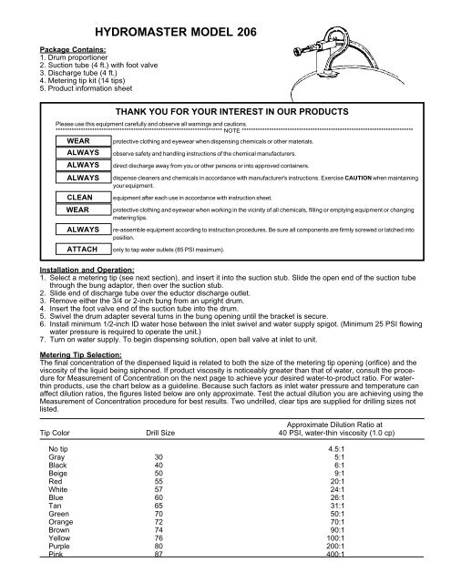
HYDROMASTER MODEL 206Package Contains:1. Drum proportioner2. Suction tube (4 ft.) with foot valve3. Discharge tube (4 ft.)4. Metering tip kit (14 tips)5. Product information sheetWEARALWAYSALWAYSALWAYSCLEANWEARALWAYSATTACHTHANK YOU FOR YOUR INTEREST IN OUR PRODUCTSPlease use this equipment carefully and observe all warnings and cautions.************************************************************************* NOTE ***************************************************************************protective clothing and eyewear when dispensing chemicals or other materials.observe safety and handling instructions of the chemical manufacturers.direct discharge away from you or other persons or into approved containers.dispense cleaners and chemicals in accordance with manufacturer's instructions. Exercise CAUTION when maintainingyour equipment.equipment after each use in accordance with instruction sheet.protective clothing and eyewear when working in the vicinity of all chemicals, filling or emptying equipment or changingmetering tips.re-assemble equipment according to instruction procedures. Be sure all components are firmly screwed or latched intoposition.only to tap water outlets (85 PSI maximum).Installation and Operation:1. Select a metering tip (see next section), and insert it into the suction stub. Slide the open end of the suction tubethrough the bung adaptor, then over the suction stub.2. Slide end of discharge tube over the eductor discharge outlet.3. Remove either the 3/4 or 2-inch bung from an upright drum.4. Insert the foot valve end of the suction tube into the drum.5. Swivel the drum adapter several turns in the bung opening until the bracket is secure.6. Install minimum 1/2-inch ID water hose between the inlet swivel and water supply spigot. (Minimum 25 PSI flowingwater pressure is required to operate the unit.)7. Turn on water supply. To begin dispensing solution, open ball valve at inlet to unit.Metering Tip Selection:The final concentration of the dispensed liquid is related to both the size of the metering tip opening (orifice) and theviscosity of the liquid being siphoned. If product viscosity is noticeably greater than that of water, consult the procedurefor Measurement of Concentration on the next page to achieve your desired water-to-product ratio. For waterthinproducts, use the chart below as a guideline. Because such factors as inlet water pressure and temperature canaffect dilution ratios, the figures listed below are only approximate. Test the actual dilution you are achieving using theMeasurement of Concentration procedure for best results. Two undrilled, clear tips are supplied for drilling sizes notlisted.Approximate Dilution Ratio atTip Color Drill Size 40 PSI, water-thin viscosity (1.0 cp)No tip 4.5:1Gray 30 5:1Black 40 6:1Beige 50 9:1Red 55 20:1White 57 24:1Blue 60 26:1Tan 65 31:1Green 70 50:1Orange 72 70:1Brown 74 90:1Yellow 76 100:1Purple 80 200:1Pink 87 400:1
Measurement of ConcentrationYou can determine the dispensed water-to-product ratio for any metering tip size and product viscosity. All that isrequired is to operate the primed dispenser for a minute or so and note two things: the amount of dispensed water/product mixture, and the amount of concentrate used in preparation of the solution dispensed. The water-to-productratio is then calculated as follows:Dilution (X) = Amount of Mixed Solution - Amount of Concentrate DrawnAmount of Concentrate DrawnDilution ratio, then, equals X parts water to one part concentrate (X:1). If the test does not yield the desired ratio,choose a different tip and repeat the test. Alternative methods to this test are 1) pH (using litmus paper), and 2)titration. Contact your concentrate supplier for further information on these alternative methods and the materialsrequired to perform them.Troubleshooting:Problem Cause Remedy1. Unit does not draw a. Clogged foot valve strainer a. Clean or replaceconcentrate b. Metering tip orifice obstructed b. Rinse orifice or replace with new tipc. Water pressure too low c. Minimum 25 PSI required. Replumb lineor use different sourced. Mineral deposits in eductor d. Descale* or replace eductore. Flooding ring not in place e. Replace discharge tube2. Water gets into a. Heavy mineral deposits in eductor a. Descale* or replace eductorconcentrate container b. Faulty or missing foot valve b. Repair or replace foot valve3. Unit continuously draws a. End of discharge tube lower than a. Always hang discharge tube from unitconcentrate eductor using hook provided on end* Mineral deposits, known as scale, may form at the discharge of the eductor, particularly in hard water areas. Toremove scale, soak the eductor in a descaling or deliming solution. Alternately, the descaling solution can besiphoned into the eductor by operating the unit with the foot valve in the descaling solution. After operating theunit in this manner for a minute, put foot valve in clear water and operate for another minute to flush the unit.Return the foot valve to the concentrate for normal use.Parts Information:1 2 3 4 5 7 8KEY PART NO. DESCRIPTION1 238100 Strainer washer2 506500 Hose swivel3 502000 Ball valveba4 234300 Nipple5 6150-K Mounting bracket6 10090910 Bung adapter assy.7 690015 Metering tip (kit)8 440121 Eductor assy.6(includes a & b)a 440100 Eductor onlyb 440101 Suction stubc9 5058-4DM Suction tube assy.9(includes c, d, e & f)c 616100 ¼" x 7" tubingd 505804 1/2" ID tubingde 250006 Ceramic weightf 10076301 Foot valve, Viton*10 5058-4DA Discharge tube assy.* EPDM foot valve available. Order 10076302.e10floodingringProportioning & Dispensing SystemsfHydro Systems Company 3798 Round Bottom Rd., Cincinnati, OH 45244 USA • (513) 271-8800965202Rev. C 1/06