data sheet - 3 phase 600 V only - Frontier Power Products
data sheet - 3 phase 600 V only - Frontier Power Products
data sheet - 3 phase 600 V only - Frontier Power Products

You also want an ePaper? Increase the reach of your titles
YUMPU automatically turns print PDFs into web optimized ePapers that Google loves.
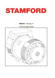
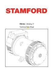
PI044H - Winding 17Technical Data SheetAPPROVED DOCUMENT
APPROVED DOCUMENT
PI044HSPECIFICATIONS & OPTIONSSTANDARDSStamford industrial generators meet the requirements ofBS EN <strong>600</strong>34 and the relevant section of otherinternational standards such as BS5000, VDE 0530,NEMA MG1-32, IEC34, CSA C22.2-100, AS1359.Other standards and certifications can be considered onrequest.VOLTAGE REGULATORAS480 AVR fitted as STANDARDTERMINALS & TERMINAL BOXStandard generators are 3-<strong>phase</strong> reconnectable with 12ends brought out to the terminals, which are mounted atthe non-drive end of the generator. Dedicated single<strong>phase</strong> generators are also available. A <strong>sheet</strong> steelterminal box contains provides ample space for thecustomers' wiring and gland arrangements. Alternativeterminal boxes are available for customers who want to fitadditional components in the terminal box.SHAFT & KEYSWith this self-excited system the main stator providespower via the AVR to the exciter stator. The highefficiency semi-conductors of the AVR ensure positivebuild-up from initial low levels of residual voltage.The exciter rotor output is fed to the main rotor through athree-<strong>phase</strong> full-wave bridge rectifier. The rectifier isprotected by a surge suppressor against surges caused,for example, by short circuit or out-of-<strong>phase</strong> paralleling.The AS480 will support limited accessories, RFIsuppession remote voltage trimmer and for the P1 range<strong>only</strong> a 'droop' Current Transformer (CT) to permit paralleloperation with other ac generators.The AVR is can be fitted to either side of the generator inits own housing in the non-drive end bracket.Excitation Boost System (EBS) (OPTIONAL)The EBS is a single, self-contained unit, attached to thenon-drive end of the generator.The EBS unit consists of the Excitation Boost Controller(EBC) and an Excitation Boost Generator (EBG). Underfault conditions, or when the generator is subjected to alarge impact load such as a motor starting, the generatorvoltage will drop. The EBC senses the drop in voltageand engages the output power of the EBG. Thisadditional power feeds the generator’s excitation system,supporting the load until breaker discrimination canremove the fault or enable the generator to pick up amotor and drive the voltage recovery.WINDINGS & ELECTRICAL PERFORMANCEAll generator stators are wound to 2/3 pitch. Thiseliminates triplen (3rd, 9th, 15th …) harmonics on thevoltage waveform and is found to be the optimum designfor trouble-free supply of non-linear loads. The 2/3 pitchdesign avoids excessive neutral currents sometimesseen with higher winding pitches, when in parallel withthe mains. A fully connected damper winding reducesoscillations during paralleling. This winding, with the 2/3pitch and carefully selected pole and tooth designs,ensures very low waveform distortion.APPROVED DOCUMENTAll generator rotors are dynamically balanced to betterthan BS6861:Part 1 Grade 2.5 for minimum vibration inoperation. Two bearing generators are balanced with ahalf key.INSULATION / IMPREGNATIONThe insulation system is class 'H'.All wound components are impregnated with materials andprocesses designed specifically to provide the high buildrequired for static windings and the high mechanicalstrength required for rotating components.QUALITY ASSURANCEGenerators are manufactured using productionprocedures having a quality assurance level to BS EN ISO9001.The stated voltage regulation may not be maintained inthe presence of certain radio transmitted signals. Anychange in performance will fall within the limits of Criteria'B' of EN 61000-6-2:2001. At no time will the steady-statevoltage regulation exceed 2%.DE RATESAll values tabulated on page 6 are subject to the followingreductions5% when air inlet filters are fitted.3% for every 500 metres by which the operating altitudeexceeds 1000 metres above mean sea level.3% for every 5°C by which the operational ambienttemperature exceeds 40°C.Note: Requirement for operating in an ambient exceeding60°C must be referred to the factory.5% For reverse rotation(Standard rotation CW when viewed from DE)NB Continuous development of our products entitles usto change specification details without notice, thereforethey must not be regarded as binding.Front cover drawing typical of product range.2
CONTROL SYSTEMVOLTAGE REGULATIONSUSTAINED SHORT CIRCUITCONTROL SYSTEMPI044HWINDING 17STANDARD AS480 AVR (SELF EXCITED)± 1.0 %SELF EXCITED MACHINES DO NOT SUSTAIN A SHORT CIRCUIT CURRENTAS480 AVR WITH OPTIONAL EXCITATION BOOST SYSTEM (EBS)SUSTAINED SHORT CIRCUIT REFER TO SHORT CIRCUIT DECREMENT CURVE (page 5)INSULATION SYSTEMPROTECTIONRATED POWER FACTORSTATOR WINDINGWINDING PITCHWINDING LEADSSTATOR WDG. RESISTANCEROTOR WDG. RESISTANCECLASS HIP230.8DOUBLE LAYER CONCENTRICTWO THIRDS120.759 Ohms PER PHASE AT 22°C SERIES STAR CONNECTED0.545 Ohms at 22°CEXCITER STATOR RESISTANCEEXCITER ROTOR RESISTANCEEBS STATOR RESISTANCER.F.I. SUPPRESSIONWAVEFORM DISTORTIONMAXIMUM OVERSPEEDBEARING DRIVE ENDBEARING NON-DRIVE ENDWEIGHT COMP. GENERATORWEIGHT WOUND STATORWEIGHT WOUND ROTORWR² INERTIASHIPPING WEIGHTS in a cratePACKING CRATE SIZETELEPHONE INTERFERENCECOOLING AIRVOLTAGE SERIES STARkVA BASE RATING FOR REACTANCEVALUESXd DIR. AXIS SYNCHRONOUSX'd DIR. AXIS TRANSIENTX''d DIR. AXIS SUBTRANSIENTXq QUAD. AXIS REACTANCEX''q QUAD. AXIS SUBTRANSIENTXL LEAKAGE REACTANCEX2 NEGATIVE SEQUENCEX0 ZERO SEQUENCEWITH EBSTHF
PI044HWinding 17Locked Rotor Motor Starting CurvesAS480 AVR Without EBS30<strong>600</strong>V25PER CENT TRANSIENT VOLTAGE DIP .201510503025APPROVED DOCUMENT0 5 10 15 20 25 30 35 40 45LOCKED ROTOR kVAAS480 AVR With EBS<strong>600</strong>VPER CENT TRANSIENT VOLTAGE DIP .201510500 5 10 15 20 25 30 35 40 45 50LOCKED ROTOR kVA4
PI044HWinding 17THREE PHASE EFFICIENCY CURVESAPPROVED DOCUMENTThree-<strong>phase</strong> Short Circuit Decrement Curve. No-load Excitation at Rated SpeedBased on star (wye) connection.1000CURRENT (Amps)100WITH EBS FITTEDSYMMETRICALASYMMETRICAL100.001 0.01TIME (secs)0.1 1 10Sustained Short Circuit = 88 AmpsNoteThe following multiplication factor should be used to convert the values from curve for thevarious types of short circuit :3-<strong>phase</strong> 2-<strong>phase</strong> L-L 1-<strong>phase</strong> L-NInstantaneousx 1.00 x 0.87 x 1.30Minimumx 1.00 x 1.80 x 3.20Sustainedx 1.00 x 1.50 x 2.50Max. sustained duration10 sec. 5 sec. 2 sec.All other times are unchanged5
PI044HWinding 17 / 0.8 <strong>Power</strong> Factor60HzClass - Temp RiseSeries Star (V)Parallel StarStar (V)Series Delta (V)kVARATINGSCont. F - 105/40°C Cont. H - 125/40°C Standby - 150/40°C Standby - 163/27°C<strong>600</strong>300<strong>600</strong>300<strong>600</strong>300<strong>600</strong>30034634634634619.721.923.023.9kW15.817.518.419.1Efficiency (%)85.584.784.383.9kW Input18.520.721.822.8APPROVED DOCUMENTDIMENSIONS6
APPROVED DOCUMENTHead Office Address:Barnack Road, StamfordLincolnshire, PE9 2NBUnited KingdomTel: +44 (0) 1780 484000Fax: +44 (0) 1780 484100www.cumminsgeneratortechnologies.comCopyright 2010, Cummins Generator Technologies Ltd, All Rights ReservedStamford and AvK are registered trade marks of Cummins Generator Technologies LtdCummins and the Cummins logo are registered trade marks of Cummins Inc.PI044H-17-TD-EN-SG-A