Section C R31.pdf
Section C R31.pdf
Section C R31.pdf

Create successful ePaper yourself
Turn your PDF publications into a flip-book with our unique Google optimized e-Paper software.
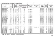
SECTION CFUSE SELECTION FOR WELDED COMPRESSORSAND COPELAMETIC COMPRESSORSMotor Running Overload Protection and Branch CircuitShort Circuit Protection are required for every compressorelectrical branch circuit. These are detailed in Articles430 and 440 of The National Electrical Code (NEC). Allinstallations and fuse selections must conform to theNEC and any specifi c local code requirements. In caseof questions, contact a qualifi ed electrician.The fuse selection procedures of the Electrical Handbookare based on time delay (dual element) sizes thatwill meet the requirements of most compressor installations.The selections conform to the National ElectricalCode short circuit requirements for single motor protection.The manufacturer of the compressor system should beconsulted in cases of multiple motor or group fusing,extreme ambient temperatures, or unusual operatingconditions where a larger fuse size than recommendedmay be required.Each compressor nameplate lists compressor data thatis needed to size short circuit protection: The Phase ofthe motor, Locked Rotor Amps (LRA), and Rated LoadAmps (RLA). (RLA is not provided on welded compressornameplates.) This data is also available in <strong>Section</strong> F.C1<strong>Section</strong> C.indd 12/5/2008 8:00:59 AM
The Electrical Handbook Fuse Selection Charts adjustthis nameplate data so that all that is necessary for standardcompressor short circuit time delay fuse protectionsizing is to answer the Selection Chart questions, determinea multiplier for RLA, and size the compressor fuseaccordingly.FUSE SELECTION PROCEDURE CHART FORWELDED COMPRESSORS AND COPELAND SCROLLCOMPRESSORS1. Determine Rated Load Amps (RLA) from nameplateor <strong>Section</strong> F.2. Determine Locked Rotor Amps (LRA) from nameplateor <strong>Section</strong> F.3. Divide LRA/RLA for Inrush Ratio.4. If fuse ambient temperature is greater than 120°F,multiply Inrush Ratio by 1.08.5. For Single Phase compressors, multiply RLA by:1.6 if Inrush Ratio is 5 or less, or1.7 if Inrush Ratio is more than 5.6. For Three Phase compressors, multiply RLA by:1.5 if Inrush Ratio is 4 or less, or1.6 if Inrush Ratio is more than 4.7. Use the next higher Time Delay fuse rating abovethe adjusted RLA value calculated in step 5 or step6.NOTE: IN NO CASE MAY FUSE RATING EXCEED225% OF COMPRESSOR RLA!C2<strong>Section</strong> C.indd 22/5/2008 8:01:07 AM
FUSE SELECTION PROCEDURE CHART FORCOPELAMETIC COMPRESSORS1. Determine Rated Load Amps (RLA) from nameplateor <strong>Section</strong> F.2. Determine Locked Rotor Amps(LRA) from nameplateor <strong>Section</strong> F.3. Divide LRA/RLA for Inrush Ratio.4. If fuse ambient temperature is greater than 120°F,multiply Inrush Ratio by 1.08.5. For Single Phase compressors, multiply RLA by:1.5 if Inrush Ratio is 5 or less, or1.6 if Inrush Ratio is more than 5.6. For Three Phase compressors, multiply RLA by:1.4 if Inrush Ratio is 4 or less, or1.5 if Inrush Ratio is more than 4.7. Use the next higher Time Delay fuse rating above theadjusted RLA value calculated in step 5 or step 6.NOTE: IN NO CASE MAY FUSE RATING EXCEED225% OF COMPRESSOR RLA!C3<strong>Section</strong> C.indd 32/5/2008 8:01:07 AM