20853_InsideSpread Revisions - Lee Spring
20853_InsideSpread Revisions - Lee Spring
20853_InsideSpread Revisions - Lee Spring
- No tags were found...

You also want an ePaper? Increase the reach of your titles
YUMPU automatically turns print PDFs into web optimized ePapers that Google loves.
Designing & SpecifyingCompression, Extension and Torsion <strong>Spring</strong>sENGINEERS GUIDE
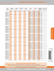
* These standards have been superceded by:BS 1726-1:2002Cylindrical helical springs made from round wire and bar -Guide to Methods of specifying, tolerances and testing -Part 1: Compression springsBS 1726-2:2002Cylindrical helical springs made from round wire and bar -Guide to methods of specifying, tolerances and testing -Part 2: Extension springsBS 1726-3:2002Cylindrical helical springs made from round wire and bar -Guide to methods of specifying, tolerances and testing -Part 3: Torsion springsThe following standards now also apply:BS 8726-1:2002Cylindrical helical springs made from rectangular and square section wire and bar -Guide to calculation and design -Part 1: Compression springsBS 8726-2:2002Cylindrical helical springs made from rectangular and square section wire and bar -Guide to calculation and design -Part 2: Torsion springsBS EN 13906-1:2002Cylindrical helical springs made from round wire and bar -Guide to calculation and deisgn -Part 1: Compression springsBS EN 13906-2:2001Cylindrical helical springs made from round wire and bar -Guide to calculation and design -Part 2: Extension springsBS EN 13906-3:2001Cylindrical helical springs made from round wire and bar -Guide to calculation and design -Part 3: Torsion springs<strong>Lee</strong> <strong>Spring</strong> - Britain's No 1 Stock <strong>Spring</strong> Supplier.We offer over 10,600 different types of compression, extension and compression springs. Thisamounts to millions of springs in stock ready for same day despatch.<strong>Spring</strong> selection kits covering the stock spring range plus selected instrument springs are alsoavailable. A custom spring design and manufacture service for compression, conical, extension,swivel hook, drawbar and torsion springs completes the package.<strong>Spring</strong>s are produced to recognised British and International standards of design andmanufacturing tolerances in materials meeting military, aerospace and/or British and DINstandards.Standard music wire and chrome silicon oil tempered springs are fully stress relieved or shotpeened to optimise performance characteristics and supplied passivated, zinc plated or paintedto enhance corrosion resistance and assist identification. Stainless steel springs are suppliedpassivated.<strong>Lee</strong> <strong>Spring</strong>'s quality system is assessed and registered with BVQI - Bureau Veritas QualityInternational to the requirements of BS EN ISO 9002 - certificate number 5692. Total batchtraceabilty is standard on every order.Call us now for a copy of our latest stock catalogue on 0118 978 1800 or request one onlinewww.leespring.co.uk
ENGINEERS GUIDETo Designing & Specifying Compression, Extension and Torsion <strong>Spring</strong>sContentsPageIntroductionIntroduction 1Compression springs 2Description 2Key design factors 2Definitions 2Calculations 3Tolerances 3-4Specifying springs 5Design alternatives 6Extension springs 7Description 7Key design factors 7Load deflection characteristics 7-8Calculations 8Tolerances 9Specifying springs 9Design alternatives 10Torsion springs 11Description 11Key design factors 11Calculations 11- <strong>Spring</strong> legs 12- Torque calculations 13- Stress calculations 13Specifying springs 14Design alternatives 15Appendices 16Definitions 16<strong>Spring</strong> materials data 17-20Finishes 20Reference information 21- Conversion data 21-22- Wire sizes 23- Using microns 24- Geometric solutions 24This guide provides detailed information on the design andspecification of compression, extension and torsion springsmanufactured from round wire.For ease of reference the structure of this guide is aligned withBS 1726 which gives standards as follows:*BS 1726 : Part 1 :*BS 1726 : Part 2 :*BS 1726 : Part 3 :Guide for the design of helicalcompression springsGuide for the design of helicalextension springsGuide for the design of helicaltorsion springsAll the essential elements of spring design and constructionare covered including formulae, tolerances, material selectionas well as the testing of dimensions, properties andperformance.The guide covers springs made from materials to:BS EN 10270-1:2001BS EN 10270-2:2001BS EN 10270-3:2001Patented cold drawn steel wire formechanical springsPre-hardened and tempered carbonand low alloy round steel wire forsprings for general engineeringpurposesStainless steel wire formechanical springsMaterials commonly used to manufacture springs include:Carbon steelsLow alloy steelsStainless steelsCopper based alloysNickel based alloysKey factors affecting material choice for a particularapplication include:• Material meets the required stress conditions eitherstatic or dynamic• Material must be capable of functioning satisfactorilyat the required operating temperature• Material is compatible with its surroundingsi.e. corrosive environment• Special requirements such as conductivity,constant modulus, weight restrictions,magnetic limitations, etc.Useful reference data on material properties and conversiontables are also included.Information included in this guide is based on <strong>Lee</strong> <strong>Spring</strong>'s90 years of experience working with engineers to developsolutions using spring technology in industries throughoutthe world.* These standards have been superceded. See adjacent page.1
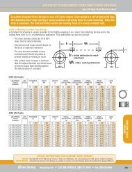
Compression springsDescriptionA compression spring is an open-coil helical spring that offers resistance to a compressive force applied axially. Such springsare usually coiled as a constant diameter cylinder; other common forms are conical, tapered, concave, convex, andcombinations of these. Most compression springs are manufactured in round wire - since this offers the best performanceand is readily available and suited to standard coiler tooling - but square, rectangular, or special-section wire can be specified.Key design factorsCompression springs should always be supplied in a stressrelievedcondition in order to remove residual bendingstresses induced by the coiling operation. Depending ondesign and space limitations, springs can be categorisedaccording to the level of stress.Specification will depend on pitch, solid height, number ofactive and total coils, free length, and the seatingcharacteristics of the spring.In designing compression springs, the space allottedgoverns the dimensional limits with regard to allowablesolid height and outside and inside diameters. Thesedimensional limits, together with the load and deflectionrequirements, determine the stress level. It is extremelyimportant that the space allotted is carefully considered sothat the spring will function properly; otherwise, costlydesign changes may be needed.Compression springs feature four basic types of ends. Acompression spring can not be ground so that its ends areconsistently square. Also the helix angles adjacent to theend coils will not be uniform either. It follows that springscan not be coiled so accurately as to permit all coils to closeout simultaneously under load. As a result the spring ratetends to lag over the initial 20% of the deflection range. Asthe ends seat during the first stage of deflection the springrate rises to the calculated value. In contrast, the springrate for the final 20% of the deflection range tends toincrease as coils progressively close out.Since the spring rate over the central 60% of the deflectionrange is linear, critical loads and rates should be specifiedwithin this range. This can be increased to about 80% oftotal deflection by special production techniques but suchmodifications will add to the cost of the spring.It is useful to note that two compression springs used in serieswill double the deflection for the same load and threesprings in series will triple the deflection for the same load.Conversely two springs in parallel will double the load forthe same deflection and three springs will triple the loadfor the same deflection.Adding springs will continue to increase the deflection andload as described.The total load is equal to the sum of the load of theindividual springs.Two compression springs 'nesting' - one inside another -should be of opposite handing to prevent coils tangling.Also it is important to allow working clearances betweenthe I.D and the O.D of the springs.<strong>Spring</strong> Index - the ratio of mean coil diameter to springwire diameter - is another key definition used to assist inthe evaluation and presentation of tolerances.The squareness of compression spring ends influences themanner in which the axial force produced by the spring canbe transferred to adjacent parts in a mechanism. In someapplications open ends may be entirely suitable; however,when space permits, closed ends afford a greater degree ofsquareness and reduce the possibility of interference withlittle increase in cost. Compression springs with closed endsoften can perform well without grinding, particularly inwire sizes smaller than 0.4mm diameter.Many applications require the ends to be ground in order toprovide greater control over squareness. Among these arethose in which heavy duty springs are specified; usually closetolerances on load or rate are needed; solid height has to beminimised; accurate seating and uniform bearing pressuresare required; and a tendency to buckle has to be minimised.A spring can be specified for grinding square in theunloaded condition, or square under load - but not in bothconditions with any degree of accuracy.DefinitionsActive coils - Coils that at any instant are contributing tothe rate of the springBuckling - Unstable lateral distortion of the major axis ofa spring when compressedClosed end - End of a helical spring in which the helix angle ofthe end coil has been reduced until it touches the adjacent coilCompression spring - A spring whose dimension reducesin the direction of the applied forceCreep - Change in length of a spring over time under aconstant forceDeflection - Relative displacement of spring endsunder loadElastic limit - Maximum stress to which a material may besubjected without permanent deformationFree length - Length of a spring when not under loadHand - Direction of spring coil helix i.e. left or rightOpen end - End of an open coiled helical spring wherethe helix angle of the end coil has not beenprogressively reducedPermanent set - Permanent deformation of a spring afterthe load has been removedPitch - Distance from one coil to the corresponding pointin the next coil measured parallel to the spring axisPrestressing (scragging) - Process where stresses areinduced into a spring to improve performanceShot peening - Process of applying shot to the surface ofa spring to induce residual stresses in the outer surface ofthe material to improve fatigue resistanceSolid force - Theoretical force of a spring whencompressed to its solid lengthSolid length - Length of a compression spring when allthe coils are in contact with each other<strong>Spring</strong> index - Ratio of mean coil diameter to materialdiameter or radial width of cross section forsquare/trapezoidal springs<strong>Spring</strong> rate - Change in load per unit of deflectionStress relieving - Low temperature heat treatment usedto relieve residual stresses, caused by the manufacturingprocess, that causes no change in the metallurgicalstructure of the spring material2
CalculationsProper design of compression springs requires knowledge ofboth the potential and the limitations of available materialstogether with simple formulae. Since spring theory is normallydeveloped on the basis of spring rate the formula for springrate is the most widely used in spring design. The primarycharacteristics useful in designing compression springs are:TermUnitS spring rate in N/mmF spring force NΔF change in spring force NΔL deflection mmD mean coil diameter mmd wire diameter mmG modulus of rigidity N/mmn number of active coils -c spring index -K stress correction factor -N total number of coils -L spring length mmL o free length of spring mmL s theoretical solid length of spring mmL s(max) maximum allowable free length mmH end fixation factor -T shear stress N/mm 2For compression springs with closed ends, ground or notground, the number of active coils (n) is two less than the totalnumber of coils (N).To determine spring rate:S = ΔF = Gd 4ΔL 8nD 3Buckling of compression springs results from the ends ofunsupported ( i.e. not used over a shaft) springs not beingground exactly square, which is commonly the case asmentioned earlier. BS 1726 : Part 1 says that a spring will buckleif the deflection as a proportion of the free length of the springexceeds a critical value of H (end fixation factor) - in theequation H /(free length of spring/mean coil diameter). Valuesof H are given for laterally and non-laterally constrainedapplications but it says the minimum figure should be 0.4 to 0.5.Solid height or lengthThe solid height of a compression spring is defined as the lengthof the spring when under sufficient load to bring all coils intocontact with the adjacent coils and additional load causes nofurther deflection. Solid height should be specified by the useras a maximum, with the actual number of coils in the spring tobe determined by the spring manufacturer.Coatings on springsFinishing springs by zinc plating and passivation mayincrease spring rate figures by effectively increasing thediameter of the wire.Tolerances<strong>Spring</strong> manufacturing, as in many other productionprocesses, is not exact. It can be expected to producevariations in such spring characteristics as load, mean coildiameter, free length, and relationship of ends or hooks.The very nature of spring forms, materials, and standardmanufacturing processes cause inherent variations. Theoverall quality level for a given spring design, however, canbe expected to be superior with spring manufacturers whospecialise in precision, high-quality components.Normal or average tolerances on performance anddimensional characteristics may be expected to be differentfor each spring design. Manufacturing variations in aparticular spring depend in large part on variations in springcharacteristics, such as index, wire diameter, number of coils,free length, deflection and ratio of deflection to free length.Tables 1 - 4 give tolerances on major spring dimensionsbased on normal manufacturing variations in compressionand extension springs.To determine spring index:c = DdCOMPRESSION AND EXTENSION SPRINGSCoil Diameter Tolerances, ± mmTo determine stress correction factor:Wire Dia.mm40.050.050.050.080.100.150.200.280.410.5360.050.080.100.130.180.230.300.380.510.76<strong>Spring</strong> Index, D/d80.080.100.150.180.250.330.430.530.661.02100.100.150.180.250.330.460.580.710.941.57120.130.180.230.300.410.530.710.891.172.03140.150.200.280.380.480.640.841.071.372.54160.180.250.330.430.560.740.971.241.633.18K = c + 0.2c - 1where c = DdTo determine shear stress:T = 8FDKπd 30.380.580.891.301.932.904.346.359.5312.70Table 13
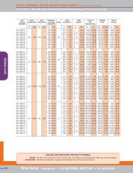
COMPRESSION SPRINGS Normal Load Tolerances, ± percent of loadLengthtolerance+/- mm1.32.53.85.1Deflection from free length to load, mm6.47.610.212.719.125.438.150.876.2101.6152.40.130.230.510.761.021.271.521.782.032.292.545.087.6210.1612.70127122268.515.522571217226.510141822255.58.51215.5192225579.51214.51719.522256810121416182022567.59101112.51415.5567891011122255.566.57.588.515.52255.566712172125555.58.5121518.579.51214.55.578.510.5Table 2COMPRESSION SPRINGSSquareness in Free-Position Tolerances (closed and ground ends), ± degreesSlendernessRatio (L/D)46<strong>Spring</strong> Index, D/d8101214160.51.01.52.03.04.06.08.010.012.0Table 33.02.52.52.52.02.02.02.02.02.03.03.02.52.52.52.02.02.02.02.03.53.02.52.52.52.52.02.02.02.03.53.03.02.52.52.52.52.02.02.03.53.03.03.02.52.52.52.52.02.03.53.53.03.02.52.52.52.52.52.04.03.53.03.03.02.52.52.52.52.5NOTE:Squareness closer than shown requires specialprocess techniques, which increase cost.<strong>Spring</strong>s with fine wire sizes, high spring indexes,irregular shapes, or long free lengths require specialconsideration in determining squareness toleranceand feasibility of grinding.It is recommended that tables 1, 2 & 3 be used as guides in establishing tolerances, particularly in estimating whether ornot application requirements may increase spring cost. In any case, as noted on the suggested specification forms thatfollow for the various spring types, mandatory specifications should be given only as required. Advisory data, which thespring manufacturer is permitted to change, in order to achieve the mandatory specifications, should be given separately.4
Specifying springsAPPLICATION FOR DESIGN OF HELICAL COMPRESSION SPRINGS1 End Coil Formation5 Assembly, or further processing detailsClosedOpenClosed and Ground2 Operation (if dynamic)6 Atmosphere, special protection detailsMinimum required lifeSpeed of operationMaximum force-lengthMinimum force-lengthcyclesHzN-mmN-mm3 Temperatures7 Surface coatingMinimum operating temperatureMaximum operating temperatureoCoC4 Material8 Other requirementsSpecification numberCircular Diameter= mmRectangular Section mm x mmHeat treatment5
Design alternativesThis chart can be used to provide guidance on how to solve certain basic compression spring design problems.Solution Condition to satisfy Increasedeflectionmm/NDecreasenumber ofcoils ‘N’Decreasemean dia‘D’Increasewire dia‘d’Decreasedeflectionrate mm/NDecreaseamount oftravelIncreaseamount oftravelIncreasenumber ofcoils ‘N’Increasemean dia‘D’Decreasewire dia‘d’Decreasemax load‘F’To increase loadX X X X XTo decrease loadX X X X XTo decrease free lengthX X X XTo increase free lengthX X X XTo decrease O.D.X X X XTo increase I.D.X X X XLoad correct at max travelbut too low at less travelX X X X XLoad correct at max travelbut too high at less travelX X X X XTo decrease actual stressX X X
Extension springsDescription<strong>Spring</strong>s that absorb and store energy by offering resistance to a pulling force are known as extension springs. Varioustypes of ends are used to attach this type of spring to the source of the force.Key design factorsThe variety of extension spring ends is limited only by theimagination of the designer. These can include threadedinserts (for precise control of tension), reduced andexpanded eyes on the side or in the centre of the spring,extended loops, hooks or eyes at different positions ordistances from the body of the spring, and evenrectangular or teardrop-shaped ends. By far the mostcommon, however, are the machine loop and cross-overloop types shown in Fig1. These ends are made usingstandard tools in one operation and should be specifiedwhenever possible in order to minimise costs.Fig. 1It should be remembered that as the space occupied bythe machine loop is shortened, the transition radius isreduced and an appreciable stress concentration occurs.This will contribute to a shortening of spring life and topremature failure. Most failures of extension springs occurin the area of the end, so in order to maximise the life ofa spring, the path of the wire should be smooth andgradual as it flows in to the end. A minimum bend radiusof 1.5 times the wire diameter is recommended.Until recently, the majority of ends were manufactured ina separate operation; nowadays, however, many ends canbe made by mechanical and computer-controlled machinesas part of the coiling operation. As there are manymachines available for coiling and looping in oneoperation, it is recommended that the spring manufacturerbe consulted before the completion of a design.Load deflection characteristicsMost extension springs are wound with initial tension - thisis an internal force that holds the coils together tightly. Themeasure of the initial tension is the load necessary toovercome the internal force and start coil separation. Unlikea compression spring, which has zero load at zero deflection,an extension spring can have a pre-load at zero deflection.In practice, this means that, before the spring willextend, a force greater than the initial tension must beapplied. Once the initial tension is overcome as thespring is pulled apart, the spring will exhibit consistentload deflection characteristics.It is useful to note that two extension springs used in serieswill double the deflection for the same load and threesprings in series will triple the deflection for the same load.Conversely two springs in parallel will double the load forthe same deflection and three springs will triple the loadfor the same deflection.Adding springs will continue to increase the deflectionand load as described.Figure 2 shows load deflection characteristics. The brokenline A shows the load required to overcome initial tensionand the deflection or spring rate of the end loops. Line Billustrates deflection when all coils are active.A spring with high initial tension will exert a high loadwhen subject to a small deflection. If this is combinedwith a low rate, the spring will exhibit an approximateconstant force characteristic.A typical use for this is the accelerator pedal of a car, wherea minimum force must be produced by the spring toovercome friction and to return the pedal. However, ondepressing the pedal, the required force does not increase.Counterbalances, electrical switchgear and tensioningdevices all make use of high initial tension - low ratesprings, whereas the one major product which calls forzero initial tension is the spring balance. To ensure zeroinitial tension the springs for balances are invariablycoiled slightly open and use screwed-in inserts forprecise rate adjustment.7
Load deflection characteristicsCalculationsTermUnitF 2F 2-F 0F 2-F 1F 1F 0Line BF 2-F 1L 2-L 1Line AF 0L 0L 1L 2c spring index -D o outside diameter mmD mean coil diameter mmd wire diameter mmF o initial tension NΔF change in spring force Nn number of active coils -L B body Length mmL o overall free length inside hooks mmL spring length mmΔL change in spring length mmΔ deflection mmS spring rate N/mmR m minimum tensile strength N/mm 2K Stress correction factor = K = c + 0.2c - 1G Modulus of rigidity N/mm 2T Shear stress N/mm 2Summary of design factors1. Stresses must always be kept lower than incompression springs because:-(a) most loops are weak(b) extension springs cannot be easily prestressed(c) extension springs cannot be easily shot peened2. The loops are active and their deflection may need tobe compensated for by a small reduction in activecoils in the order of 0.1 to 0.25 turns3. The initial tension should be within the preferred rangefor optimum tolerances4. Do not use large loops or screwed-in inserts unless theapplication demands it5. Use modified compression spring Goodman diagrams todesign for dynamic applications6. Heat treatment raises the elastic limit but reduces initial tension7. The higher the wire strength, the higher the initial tensionFormlae:Shear stress due to load F :<strong>Spring</strong> rate:T = 8FDKπd 3S = ΔF = Gd 4ΔL 8nD 3Free length inside hooks:Initial tensionL o = (n +1) d + 2 (D - d)F o = F 2 - F 2 - F 1 (L 2 - L o )L 2 - L 1F o = F 2 - S (L 2 - L o )8
TolerancesFor guidance on tolerances refer to the compression spring tables 1 to 3 on pages 3-4Specifying springsAPPLICATION FOR DESIGN OF HELICAL EXTENSION SPRINGS1 End Loop Form5 Assembly, or further processing detailsType (see clause 6)Relative positionWhere important, loop details, dimensions and themethod of fixing are to be given on a separatesheet of paper and attached to this data sheet.2 Operation (if dynamic)6 Atmosphere, special protection detailsMinimum required lifeSpeed of operationMaximum force-lengthMinimum force-lengthcyclesHzN-mmN-mm3 Temperatures7 Surface coatingMinimum operating temperatureMaximum operating temperatureoCoC4 Material8 Other requirementsSpecification numberCircular Diameter= mmRectangular Section mm x mmHeat treatment9
Design alternativesThis chart can be used to provide guidance on how to solve certain basic extension spring design problems.Solution Condition to satisfy Increasedeflectionmm/NDecreasenumberof coils ‘N’Decreasemean dia‘D’Increasewire dia‘d’Use intialtensionDecreasedeflectionrate mm/NDecreaseamountof travelIncreaseamountof travelIncreasenumberof coils ‘N’Increasemean dia‘D’Decreasewire dia‘d’Cut downlength ofend loopsIncreaselength ofend loopsDecreasemax load‘F’To increase loadX X X X X XTo decrease loadX X X X XTo decrease free lengthX X X X X XTo increase free lengthX X X X X XTo decrease O.D.X X X XLoad correct at max travelbut too low at less travelX X X X X XLoad correct at max travelbut too high at less travelX X X X XTo decrease actual stressX X X
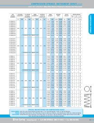
Torsion springsDescriptionTorsion springs, have ends which are rotated in angular deflection to offer resistance to externally applied torque. Thewire itself is subjected to bending stresses rather than torsional stresses. <strong>Spring</strong>s of this type usually are close-wound; theyreduce in coil diameter and increase in body length as they are deflected. The designer must also consider the effects offriction and of arm deflection on torque.Key design factorsSpecial types of torsion springs include double-torsionsprings and springs having a space between the coils in orderto minimise friction. Double-torsion springs consist of oneright-hand and one left-hand coil section, connected, andworking in parallel. The sections are designed separatelywith the total torque exerted being the sum of the two.The types of ends for a torsion spring must be consideredcarefully. Although there is a good deal of flexibility inspecifying special ends and end-forming, costs might beincreased and a tooling charge incurred. Designers shouldcheck nominal free-angle tolerances relating to applicationrequirements in the details given in tabular informationprepared by manufacturers. It should be noted that inaddition to the supply of specification information, thedesigner should provide a drawing which indicates endconfigurations which are acceptable to the application.It is 'good practice' to use both left and right handwindings when ever possible.CalculationsTermUnitc spring indexD mean coil diameter mmd material diameter mmE modulus of elasticity M/mm 2F <strong>Spring</strong> force NK o stress correction factor for circularsection wire -L o Free body length mmL t Loaded body length mmL 1 Length of leg one mmL 2 Length of leg two mmn number of active coils in spring -σ bending stress in spring N/mmS θ nominal torsional rate N.mm/degreeT torque at any angle N.mmΔT change in torque N.mmθ angular rotation of spring degreesTorsion <strong>Spring</strong>sCoil Diameter Tolerances, ± mmStress correction factorsStress correction factor K ogiven by the equation:K o =cc - 0.75where c = D/dfor round section materials isStressThe bending stress for round section materials is given bythe equation:σ = 32T K oπd 3Torsional rateThe torsional rate for round section material is given by theequation:S θ = ΔT = Ed 4θ 3667nDTorsion <strong>Spring</strong>sCalculated free relative leg orientation tolerance ± degreesWire Dia.mm.46<strong>Spring</strong> Index, D/d810121416Number ofcoils46<strong>Spring</strong> Index (c)8101214160.380.580.891.301.932.904.346.35Table 40.050.050.050.050.080.100.150.200.050.050.050.080.130.180.250.360.050.050.080.130.180.250.330.560.050.080.100.180.230.330.510.760.080.100.150.200.300.460.691.020.080.130.180.250.380.560.861.270.100.150.230.300.460.711.071.522345681015202530508889111315202429324688101113161824303540578911131518212835404666810131517202432394551738111416182226354249568091215172024283746536187101316192126304049576593Table 511
α =0 o 90 o 180 o 315 oAxialTangentialRadialOne radial overcentreleg andone tangential legConventions for describing relative leg orientationDimensional changesIn use the dimensions of torsion springs change. This iscaused by the action of winding the spring up undertorque and unwinding. During winding the followingchanges occur:The number of coils in the spring increases - one completeturn of 360º of one leg will increase the number of coils inthe spring by one.Subsequently spring length increases one coil.The mean coil diameter of the spring decreases - as thewire length remains the same during coiling, the additionalmaterial for the extra coils is drawn from a reduction inspring diameter. This reduction in mean coil diameter isproportional to the increase in the number of coils.Depending upon the spring design (few coils) thereduction in diameter can be significant.This reduction can be calculated using the following formula:Mean coil diameter at working position =Number of coils in free position x mean coil in free positionNumber of coils in working positionBearing mind these factors it is necessary to take accountof the reduction in spring diameter if a spring is tooperate on a mandrel or in a tube. Failure to leaveadequate clearances between the inside diameter of thespring and the mandrel will cause the body of the springto lock up on the mandrel, leaving the legs to takeadditional deflection and stress. In this situation the legswill take an immediate permanent set, altering thespring characteristics and failing to provide the designedfunction. Secondly, the increase in body length must alsobe considered to ensure there is adequate clearance forthe spring body to grow. Otherwise a similar situationwill occur resulting in a permanent loss of springperformance and spring failure.It is advised that a clearance equal to 10% of the springdimensions is left between the inside diameter and themandrel and between body length and housing length.<strong>Spring</strong> legsPrior to the designing of a spring it is necessary to knowthe deflection and leg position requirements. The legrelationship for the spring can be specified in one of twoways.1.Required torque developed after a deflection of 0 degrees.This method does not specify the relative angle of thetwo legs either in the free position or the workingposition of the spring.Consequently the spring can be designed with any numberof whole or partial coils to achieve the required torquedeflection relationship. The leg relationship in the freeposition is then a result of the number of coils determined.2.Required torque developed at a specified angle of thetwo legs relative to each other. When the spring rate isspecified or calculated from additional torque deflectioncharacteristics, the relative angle of the two legs in thefree position may be calculated.12
Torque calculationsSometimes the requirements for a spring will be specified as atorque and other times as a load. Consequently it is necessaryin the latter instance to convert the load to a torque.Torque = Applied load x distance to spring axisIt is important to note that the distance from the line ofaction of the force to the centre axis of the spring is atright angles to the line of force. For the example above thedistance is the same as the leg length for a tangential legspring when the force is acting at right angles to the leg.For a spring with radial legs the torque would becalculated as follows:T = F x LDeflection calculationBased upon the spring dimensions the predicted deflectionmay be calculated for a specified torque using thefollowing formula:Deflection θ = 64T L 1 + L 2 + NπD x 180Eπd 4 3 πThe units for the above are degrees. However, sometimesdrawings are specified in radians or turns, to convert usethe following factors:Degrees to radians multiple by n and divide by 180Degrees to turns divide by 360Sometimes the above formula is simplified as follows:θ = 64T ND x 180Ed 4πThis is only true for the case where the spring does not haveany legs and so no account is made for leg deflection.It is recommended that only the full formula above is alwaysused to automatically account for leg deflection. As thisportion of the total deflection can be very significantdependent upon the spring design (total coils and leg length).Rate calculationThe rate (S) of a torsion spring is a constant for any spring designand is the amount of increase in torque for a given deflection.For a spring with a deflection of 0 from free, under anapplied Torque (T), the rate is the change in torque dividedby the deflection.Stress calculationsUnlike compression and extension springs where theinduced stress is torsional, torsion springs operate inbending inducing a bending stress, which is directlyproportional to the torque carried by the spring and iscalculated as follows:σ = 32Tπd 3Once again this formula can be transposed when the allowablestress is known to determine wire diameter or torque.Body length calculationThe body length of a close coiled spring in the free position:L 0 = (n + 1)dIn the working position the body length is:L t = n + 1 + θ d360Stresses<strong>Spring</strong>s are stressed in bending and not torsion, as in thecase for compression and extension springs. As aconsequence torsion springs can be stressed higher thanfor compression springs.For example, with a patented carbon steel to BS 5216, anun-prestressed compression spring can be stressed up to49% of tensile whilst an un-prestressed torsion spring canbe stressed up to 70% of tensile strength.Unlike compression springs, which fail safe by going solid whenoverloaded, a torsion spring can easily be overstressed. It istherefore important that sufficient residual range is alwaysdesigned into the spring. This is performed by always designingthe spring to a torque I5% greater than the required torque.A suitable low temperature heat treatment of the springsafter coiling can raise the maximum permissible workingstress considerably. For example, with BS 5216 material themaximum stress level can be increased to about 85%.An important fact relating to the heat treatment of torsionsprings is that they will either wind up or unwind accordingto material. (For example carbon steel will wind up whilststainless steel will unwind).S = TθAlternatively, if the torque at two angular leg positions isknown then the rate is the change in torque divided by thechange in leg angle.13
Specifying springsAPPLICATION FOR DESIGN OF HELICAL TORSION SPRINGSWhere important, full details of the spring leg forms and/or space enveloped should be included here.1 Leg formOneBothAxial Tangential 5 Service temperaturesMax. operating temp ( o C)Min. operating temp ( o C)Radial (external) Radial (over-centre) Working life(h)Other 2 Limiting dimensionsMaximum allowable outside diameterMandrel diameterMaximum allowable body lengthmmmmmm6 Service environment3 Torque and rate requirementsPre-load positionMax. working position7 Finishα degree degreeT N-mm N-mmT tol ± N-mm ± N-mm8 Other requirementsLoading Increasing torque/ Increasing torque/direction decreasing torque decreasing torqueTorsional rate S θ =Assembly adjustment Yes/NoN-mm/degreedegree4 Mode of operationRequired life (cycles)Operating speed(cycles/min)Serial/design/Part No.14
Design alternativesThis chart can be used to provide guidance on how to solve certain basic torsion spring design problems.Solution Condition to satisfy Increasedeflection rateM/360degDecreasenumber of coils‘N’Decrease meandia ‘D’Increasewire dia ‘d’Decreasedeflection rateM/360degDecrease amountof angulardeflection‘θ’Increase amountof angulardeflection‘θ’Increasenumber of coils‘N’Increasemean dia ‘D’Decreasewire dia ‘d’Decrease maxmoment ‘M’To increase loadX X X X XTo decrease loadX X X X XTo decrease body lengthX X X XTo increase body lengthX X X XTo decrease O.D.X X X XTo increase I.D.X X X XLoad correct at max travelbut too low at less travelX X X X XLoad correct at max travelbut too high at less travelX X X X XTo decrease actual stressX X X
AppendicesDefinitions (as given in BS 1726)16Active coils (effective coils, working coils). The coils of a springthat at any instant are contributing to the rate of the spring.Buckling. The unstable lateral distortion of the major axis of aspring when compressed.Closed end. The end of a helical spring in which the helixangle of the end coil has been progressively reduced until theend coil touches the adjacent coil.Compression spring. A spring whose dimension, in the directionof the applied force, reduces under the action of that force.Compression test. A test carried out by pressing a spring to aspecified length a specified number of times.Creep. The change in length of a spring over time whensubjected to a constant force.Deflection. The relative displacement of the ends of a springunder the application of a force.Elastic deformation. The deformation that takes place when amaterial is subjected to any stress up to its elastic limit. Onremoval of the force causing this deformation the materialreturns to its original size and shape.Elastic limit (limit of proportionality). The highest stressthat can be applied to a material without producingpermanent deformation.End fixation factor. A factor used in the calculation of bucklingto take account of the method of locating the end of the spring.Extension spring. A spring whose length, in the direction ofthe applied force, increases under the application of that force.Fatigue. The phenomenon that gives rise to a type of failurewhich takes place under conditions involving repeated orfluctuating stresses below the elastic limit of the material.Fatigue limit. The value, which may be statisticallydetermined, of the stress condition below which material mayendure an infinite number of stress cycles.Fatigue strength (endurance limit). A stress condition underwhich a material will have a life of a given number of cycles.Fatigue test. A test to determine the number of cycles of stressthat will produce failure of a component or test piece.Finish. A coating applied to protect or decorate springs.Free length. The length of a spring when it is not loaded.NOTE. In the case of extension springs this may include the anchor ends.Grinding. The removal of metal from the end faces of a springby the use of abrasive wheels to obtain a flat surface which issquare with the spring axis.Helical spring. A spring made by forming material into a helix.Helix angle. The angle of the helix of a helical coil spring.Hysteresis. The lagging of the effect behind the cause of theeffect. A measure of hysteresis in a spring is represented bythe area between the loading and unloading curves producedwhen the spring is stressed within the elastic range.Index. The ratio of the mean coil diameter of a spring to thematerial diameter for circular sections or radial width of crosssection for rectangular or trapezoidal sections.Initial tension. The part of the force exerted, when a closecoiled spring is axially extended, that is not attributable to theproduct of the theoretical rate and the measured deflection.Inside coil diameter of a spring. The diameter of the cylindricalenvelope formed by the inside surface of the coils of a spring.Loop (eye, hook). The formed anchoring point of a helicalspring or wire form. When applied to an extension spring, itis usually called a loop. If closed, it may be termed an eye andif partially open may be termed a hook.Modulus of elasticity. The ratio of stress to strain withinthe elastic range.NOTE. The modulus of elasticity in tension or compression is also known asYoung's modulus and that in shear as the modulus of rigidity.Open end. The end of an open coiled helical spring in which thehelix angle of the end coil has not been progressively reduced.Outside coil diameter. The diameter of the cylindrical envelopeformed by the outside surface of the coils of a spring.Permanent set (set). The permanent deformation of a springafter the application and removal of a force.Pitch. The distance from any point in the section of any onecoil to the corresponding point in the next coil whenmeasured parallel to the axis of the spring.Prestressing (scragging). A process during which internalstresses are induced into a spring.NOTE. It is achieved by subjecting the spring to a stress greater than that towhich it is subjected under working conditions and higher than the elastic limitof the material.The plastically deformed areas resulting from this stress cause anadvantageous redistribution of the stresses within the spring. Prestressing canonly be performed in the direction of applied force.Rate (stiffness). The force that has to be applied in order toproduce unit deflection.Relaxation. Loss of force of a spring with time when deflectedto a fixed position.NOTE. The degree of relaxation is dependent upon, and increases with, themagnitude of stress, temperature and time.Safe deflection. The maximum deflection that can be appliedto a spring without exceeding the elastic limit of the material.Screw insert. A plug screwed into the ends of a helicalextension spring as a means of attaching a spring to anothercomponent. The plug has an external thread, the diameter,pitch and form of which match those of the spring.Shot peening. A cold working process in which shot isimpacted on to the surfaces of springs thereby inducingresidual stresses in the outside fibres of the material.NOTE. The effect of this is that the algebraic sum of the residual and appliedstresses in the outside fibres of the material is lower than the applied stress,resulting in improved fatigue life of the component.Solid length. The overall length of a helical spring when eachand every coil is in contact with the next.Solid force. The theoretical force of a spring when compressedto its solid length.Space (gap). The distance between one coil and the next coilin an open coiled helical spring measured parallel to the axisof the spring.<strong>Spring</strong> seat. The part of a mechanism that receives the endsof a spring and which may include a bore or spigot tocentralize the spring.Stress (bonding stress, shear stress). The force divided by thearea over which it acts. This is applied to the material of thespring, and for compression and extension springs is in torsionor shear, and for torsion springs is in tension or bending.Stress correction factor. A factor that is introduced to makeallowance for the fact that the distribution of shear stressacross the wire diameter is not symmetrical.NOTE. This stress is higher on the inside of the coil than it is on the outside.Stress relieving. A low temperature heat treatment carriedout at temperatures where there is no apparent range in themetallurgical structure of the material. The purpose of thetreatment is to relieve stresses induced during manufacturingprocesses.Variable pitch spring. A helical spring in which the pitch of theactive coils is not constant.
<strong>Spring</strong> Materials Data<strong>Spring</strong> materials - Summary table … Continued overleafMaterialSpecification Grade/TypeBS 521612 + 3M4M5095A65094A65093A65Size Min UTSRange (mm) Range (N/mm 2 )0.2 - 9.00.2 - 13.20.1 - 4.00.1 - 3.00.25 - 12.5370 - 9402640 - 10403020 - 17703400 - 20001910 - 1240SurfaceQualitiesNSHS, ND, HDM, Ground MMNSHS, NDHDHeat TreatmentAfter CoilingSR (1) 300/375 o C1.5 hrMax CorrosionServ.Temp Resistance150170FatigueResistancePoor NS,HS:N/A (2)HD:ExcellentM: V GoodGr.M: ExcellentNS, HS: N/AND; GoodHD; V GoodBS 2803735A654735A65685A55:R1685A55:R21.0 - 12.51.0 - 12.51970 - 13601910 - 13501950 - 14602100 - 1610HS, ND, HDSR 350/450 o C1.5 hr200250PoorHS; N/AND; GoodHD; Excellent090A65070A72060A69BS 1429 1.0 - 16.0 1740 - 1290 NS, ND, HD735A50H/T (3) tohardnessrequired170200PoorNS; N/AND; GoodHD; V Good685A55250BS 970:Pt 1080A67060A7812.0 - 16.01740 - 1290 Black BarGround BarH/T to hardnessrequired170 Poor Black Bar; PoorGround Bar; Good251A58250A6012.0 - 16.012.0 - 25.0170BS 970:Pt 2525A58525A60525A61685A57704A60705A6012.0 - 25.012.0 - 40.012.0 - 54.012.0 - 40.012.0 - 80.01740 - 1290Black Bar,Peeled or,Turned Bar,Ground BarH/T to hardnessrequired170250170PoorBlack Bar; PoorPeeled orTurned Bar; GoodGround Bar; Good735A51735A5412.0 - 40.012.0 - 54.0200925A6012.0 - 80.0170805H6012.0 - 80.0200BS 2056(austenitic)302S26;GrI302S26;GrII301S26;GrI301S26;GrII316S33316S42305S11904S140.08 - 4.00.08 - 10.00.08 - 6.00.08 - 10.00.08 - 10.00.08 - 10.00.08 - 10.00.08 - 10.01880 - 12302160 - 12301920 - 12002200 - 12501680 - 8601680 - 8601680 - 8601600 - 1150As drawnorAs drawn& polishedSR 450 o C 1 /2 hr 300 Good Poor17
… <strong>Spring</strong> materials - Summary table ContinuedMaterialSpecification Grade/TypeBS 2056(pcpn.harden)BS 2056(martensitic)BS 970: Pt 1Size Min UTSRange (mm) Range (N/mm 2 )SurfaceQualitiesHeat TreatmentAfter CoilingMax CorrosionServ.Temp ResistanceASTM B166-84 <strong>Spring</strong> Temper 0.30 - 14.3 1275 - 965 As drawn SR 450 o C: 1hr 340 Excellent PoorAMS 5699DAMS 5698D<strong>Spring</strong> TemperNo. 1 Temper0.30 - 15.50.30 - 12.51515 - 12401140 - 1070As drawnA.650 o C: 4hrsA.735 o C: 16hrs370550Excellent PoorBS 3075 GrNA18 Cold Drawn 0.45 - 8.0 1240 - 1170 As drawn A.590 o C: 8hrs 260 Excellent PoorASTM B164-84 <strong>Spring</strong> Temper 0.30 - 14.3 1140 - 830 As drawn SR 310 o C: 1 /2hr 200 Excellent PoorBS 2786**BS 2873301S81420S45402S29Cold DrawnBS 3075 GrNA19Sol TreatedCZ 107: 1 /2HCZ 107: HCZ 107: EHPB 102: 1 /2HPB 102: HPB 102: EHPB 103: 1 /2HPB 103: HPB 103: EHCB 101WPCB 101W(H)P0.25 - 10.05.00 - 10.010.0 - 70.00.45 - 10.00.45 - 10.00.50 - 10.00.50 - 10.00.50 - 6.00.50 - 10.00.50 - 10.00.50 - 6.00.50 - 10.00.50 - 10.00.50 - 6.00.50 - 10.00.50 - 3.02230 - 1470 As drawn2000 - 1740 As drawn &softened460 min700 min740 - 695540 min700 min850 - 800590 min740 min900 - 8501050 min1240 minAs drawnAs drawnAs drawnA (4) 480 o C 1hrH/T to hardnessrequired1650 - 1470 Bright Bar H/T to hardnessrequired1540 - 13101080As drawnA.650 o C: 4hrsA.750 o C: 4hrsSR 180/230 o C:1/2hrSR 180/230 o C:1/2hrA.335 o C: 2hrs320 Good Poor300 Good Poor320 Good Poor35035080 Good V.Poor80125Excellent PoorGoodGoodFatigueResistancePoorPoorKEY1. SR = Stress Relieve2. N/A = Not Applicable3. H/T = Harden and Temper4. A = Ageing (Precipitation Hardening)5. Corrosion Ratings = Poor, Good, Excellent6. Fatigue Ratings = V Poor, Poor, Good, V Good, Excellent**Now BS EN 12166: 199818
Maximum permissible stresses for springs - Static applicationsMaterialPatented cold drawn springsteel wirePrehardened and temperedcarbon steel and low alloy wireSteels hardened andtempered after coilingcarbon & low alloyAustenitic stainless steel wireMartensitic stainless steel wirePrecipitation hardeningstainless wire<strong>Spring</strong> brass wireExtra hard phosphor-bronzewireBeryllium-copper wireMonel alloy 400Monel alloy K 500Inconel alloy 600Inconel alloy X 750Nimonic alloy 90SpecificationUnprestressedCompressionand Extension<strong>Spring</strong>sMaximum Static StressesPrestressedCompression<strong>Spring</strong>sUnprestressedTorsion<strong>Spring</strong>sPrestressedTorsion<strong>Spring</strong>s% R m % R m % R m % R mBS 5215, BS 1408 49 * 70 70 100BS 2803 53 70 70 100BS 1429,BS 970 Parts 1&2BS 2056 Gr 302S25BS 2056 Gr 420S45BS 2056 Gr 301S81**BS 2873 Gr CZ107**BS 2873 Gr PB102/103**BS 2873 Gr CB 101ASTM B164-90BS 3075 Gr NA18ASTM B166-91AMS 5699CBS 3075 Gr NA1953 70 70 100Ni-span alloy C902 40 53 70 100*N.B. For unprestressed compression and extension springs in static applications the LTHT (low temperature heattreatment) after coiling may be omitted only for BS 5216 and BS 2056 austenitic stainless materials. In this case, themaximum solid stress is reduced to 40% R m for BS 5216 springs and 30% R m for austenitic stainless springs.**Now BS EN 12166: 1998Elastic modulus values for spring materials40 *5353404040404042424259707059595953535555557070707070707070707070100100100100100100100100100100100MATERIAL E GkN/mm 2 kN/mm 2Cold drawn carbon steel 207 79.3Hardened and tempered carbon steel 207 79.3Hardened and tempered low alloy steels 207 79.3Austenitic stainless 187.5 70.3Martensitic stainless 207 79.3Precipitation hardening stainless 200 76.0Phosphor-bronze 104 44.0<strong>Spring</strong> brass 104 38.0Copper-beryllium 128 48.3Monel alloy 400 + K500 179 65.5Inconel 600 + X750 214 76.0Nimonic alloy 90 224 84.0Titanium alloys 110 37.9Ni-span alloy C902, Durinval C 190 65.0NOTE: The above are average room temperature values. With some materials these values can vary significantly withmetallurgical conditions.As a guide to change in modulus with temperature value of 3% change per 100 o C will give sufficient accuracy for all theabove materials except Ni-span C902 which has a constant modulus with temperature. For all the other spring materialsmodulus decreases with increasing temperature.19
Maximum operating temperatures for spring materials600600500500400400Temperature o C300300200100PhosphorBronzeCopperBerylliumAlloysPatented CarbonSteelsHardened andTempered Carbon SteelsCr V SteelSi Cr SteelAustenitic Stainless Steel17/7PH Stainless SteelInconel Alloy 60018% Ni Maraging SteelTungsten Tool Steels (High Speed)ElgiloyA 286Nimonic Alloy 90Inconel Alloy X750200100MaterialFinishes<strong>Spring</strong>s made from carbon and alloy steels are particularlysubject to corrosion. As well as spoiling the appearance ofthe spring, rusting can lead to pitting attack and can oftenresult in complete failure of the component.To prevent rusting, the steel surface should be isolatedfrom water vapour and oxygen in the atmosphere at allstages of spring processing, storage and service, byapplication of a suitable protective coating.Several temporary protective coatings are available toprevent corrosion in springs during processing and storage.The term 'temporary' does not refer to the duration ofcorrosion protection, but indicates only that the protectivecoating can be easily applied and removed as required.Nevertheless, temporary coatings are not suitable for longterm protection of springs against corrosion in damp,humid or marine environments.More durable coatings are therefore needed to protectsprings throughout their service life.Electroplated zinc and cadmium coatings have been usedfor many years to protect springs against corrosion duringservice. These metallic coatings act sacrificially to protectthe spring, even when the coating is breached to exposethe steel surface. However, electroplated springs can breakdue to hydrogen embrittlement introduced during theplating process.New methods have now been developed for depositingzinc rich coatings onto the steel surface withoutintroducing hydrogen embrittlement. The zinc can bemechanically applied during a barrelling process, or can becontained within the resin base with which the spring iscoated during a dip/spin process, to give uniform coverage,even over recessed surfaces.Paint and plastic coatings can also be used to protectsprings against corrosion in service, neither of whichprotect the springs sacrificially. As a result, the success orfailure of these coatings is critically dependent upon theirability to prevent the corrosive environment from reachingthe steel surface. Good adhesion to the steel surface,flexibility and resistance to the environment are thereforerequired for paints and plastic coatings used to protectsprings against corrosion.Developments in coating technology have produced severalnew coatings which can be used to protect springs againstcorrosion at various stages of manufacture and service.The IST (Institute of <strong>Spring</strong> Technology) has evaluatedtemporary coatings, metallic coatings, paint and plasticscoatings in detail and results are available from them orask you supplier.20
Conversion dataQuantity To convert from To Multiply byLength Feet (ft) Metres 0.3048Millimetres 304.8Metres (m) Feet 3.2808Inches 39.3701Inches (in) Metres 0.0254Millimetres 25.4Area Square Inches (in 2 ) Square Millimetres 645.16Square Millimetres (mm 2 ) Square Inches 0.00155Volume Cubic Inches (in 3 ) Cubic Millimetres 16387.064Cubic Millimetres (mm 3 ) Cubic Inches 0.000061024Force Pounds Force (lbf) Newtons 4.4498Kilograms Force 0.4536Newtons (N) Pounds Force 0.2247Kilograms Force 0.102Kilograms Force (kgf) Newtons 9.81Pounds Force 2.2046Rate Pounds Force per Inch (Ibf/in) Kilograms Force per Millimetre 0.017858Newtons per Millimetre 0.17519Newtons per Millimetre (N/mm) Pounds Force per Inch 5.7082Kilograms Force per Millimetre 0.102Kilograms Force per Millimetre Newtons per Millimetre 9.81(kgf/mm) Pounds Force per Inch 55.997Torque Pound Force-inch (Ibf/in) Kilogram Force-Millimetre 11.52136Newton-Metre 0.11302Newton-Metre (Nm) Pound Force-inch 8.84763Ounce Force-inch 141.562Kilogram Force-Millimetre 101.937Kilogram Force-Millimetre Pound Force-inch 0.086796(kgf/mm) Newton-Metre 0.00981Ounce Force-inch 1.3887Ounce Force-inch (ozf/in) Pound Force-inch 0.0625Newton-Metre 0.007064Kilogram Force-Millimetre 0.7221
Standard wire gaugeSWG IMPERIAL METRIC0000000 0.5000 12.7000000000 0.4640 11.785600000 0.4320 10.97280000 0.4000 10.1600000 0.3729 9.448800 0.3480 8.83920 0.3240 8.22961 0.3000 7.62002 0.2760 7.01043 0.2520 6.40084 0.2320 5.89285 0.2120 5.38486 0.1920 4.87687 0.1760 4.47048 0.1600 4.06409 0.1440 3.657610 0.1280 3.251211 0.1160 2.946412 0.1040 2.641613 0.0920 2.336814 0.0800 2.032015 0.0720 1.828816 0.0640 1.625617 0.0560 1.422418 0.0480 1.219219 0.0400 1.016020 0.0360 0.914421 0.0320 0.812822 0.0280 0.711223 0.0240 0.609624 0.0220 0.558825 0.0200 0.508026 0.0180 0.457227 0.0164 0.416628 0.0148 0.375929 0.0136 0.345430 0.0124 0.315031 0.0116 0.294632 0.0108 0.274333 0.0100 0.254034 0.0092 0.233735 0.0084 0.213436 0.0076 0.193037 0.0068 0.172738 0.0060 0.152439 0.0052 0.132140 0.0048 0.121941 0.0044 0.111842 0.0040 0.101643 0.0036 0.091444 0.0032 0.081345 0.0028 0.071146 0.0024 0.061047 0.0020 0.050848 0.0016 0.040649 0.0012 0.030550 0.0010 0.025423
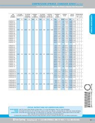
Using microns0.00254mm(0.0001")Human Hair Size0.0762mm (0.003")Particle of Dust0.004mm (0.000157")NOT SHOWN TO SCALE0.0254mm(0.001")Particle of Cigarette Smoke0.0025mm (0.000098")0.001mm (0.00003937")THE MICRONGeometric solutionsThe Diameter of a Circle equal in area to a given Square - multiply one side of the Square by 1.12838The Side of a Hexagon inscribed in a Circle - multiply the Circle Diameter by 0.5The Diameter of a Circle inscribed in a Hexagon - multiply one side of the Hexagon by 1.7321The Side of an Equilateral Triangle inscribed in a Circle - multiply the Circle Diameter by 0.866The Diameter of a Circle inscribed in an Equilateral Triangle - multiply one Side of the Triangle by 0.57735The Area of a Square or Rectangle - multiply the base by the heightThe Area of a Triangle - multiply the Base by half the PerpendicularThe Area of a Trapezoid - multiply half the sum of Parallel sides by the PerpendicularThe Area of a Regular Hexagon - multiply the square of one side by 2.598The Area of a Regular Octagon - multiply the square of one side by 4.828The Area of a Regular Polygon - multiply half the sum of Sides by the Inside RadiusThe Circumference of a Circle - multiply the Diameter by 3.1416The Diameter of a Circle, multiply the Circumference by 0.31831The Square Root of the Area of a Circle x 1.12838 = the DiameterThe Circumference of a Circle x 0.159155 = the RadiusThe Square Root of the area of a Circle x 0.56419 = the RadiusThe Area of a Circle - multiply the Square of the Diameter by 0.7854The Square of the Circumference of a circle x 0.07958 = the AreaHalf the circumference of a Circle x half its diameter = the AreaThe Area of the Surface of a Sphere - multiply the Diameter Squared by 3.1416The Volume of a Sphere - multiply the Diameter Cubed by 0.5236The Area of an Ellipse - multiply the Long Diameter by the Short Diameter by 0.78540To find the Side of a Square inscribed in a Circle - multiply the Circle Diameter by 0.7071To find the Side of a Square Equal in Area to a given Circle - multiply the Diameter by 0.8862References:BS 1726 : Parts 1, 2 & 3. These standards have been superceded. See inside front cover.Institute of <strong>Spring</strong> Technology.The information given in this catalogue is as complete and accurate as possible at the time of publication. However, <strong>Lee</strong><strong>Spring</strong> reserve the right to modify this data at any time without prior notice should this become necessary.24
Conversion dataStress Pound Force per Square Inch kgf/mm 2 0.000703(Ibf/in 2 ) hbar 0.000689N/mm 2 0.006895tonf/in 2 0.000446Kilogram Force per Square lbf/in 2 1422.823Millimetre (kgf/mm 2 ) hbar 0.981N/mm 2 9.81tonf/in 2 0.635Hectobars lbf/in 2 1450.38N/mm 2 10kgf/mm 2 1.019368tonf/in 2 0.6475Newton per Square Millimetre lbf/in 2 145.038(N/mm 2 ) kgf/mm 2 0.101937hbar 0.1tonf/in 2 0.06475Ton Force per Square Inch lbf/in 2 2240.0(tonf/in 2 ) kgf/mm 2 1.5743hbar 1.54442N/mm 2 15.4442Length 1 cm = 0.3937 in 1 in = 25.4 mm 1 m = 3.2808 ft1 ft = 0.3048 m 1 km = 0.6214 mile 1 mile = 1.6093 kmWeight 1 g = 0.0353 oz 1 oz = 28.35 g1 kg = 2.2046 lb 1 lb = 0.4536 kg1 tonne = 0.9842 ton 1 ton = I.0I6 tonneArea 1 m 2 = 1.196 yard 2 1 in 2 = 645.2 mm 21 hectare = 2.471 acre 1 yard 2 = 0.8361 m 21 acre = 0.4047 hectare 1 sq mile = 259 hectare22
<strong>Lee</strong> <strong>Spring</strong> Limited, Latimer Road, Wokingham, Berkshire RG41 2WA.Tel: 0118 978 1800. Fax: 0118 977 4832.sales@leespring.co.ukwww.leespring.co.uk